![]()
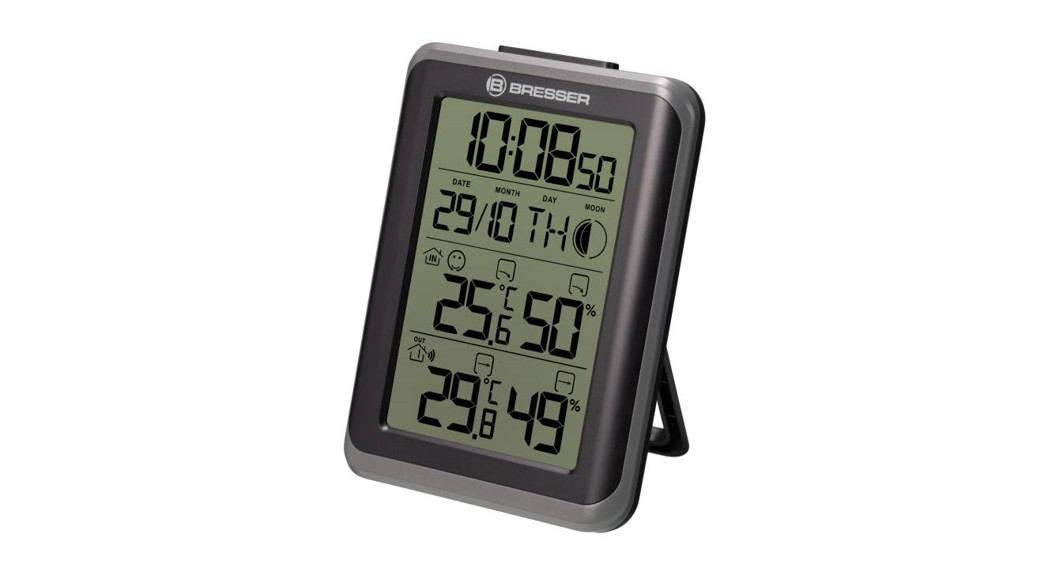
Wetterstation
- Weather Station
MyClimate Thermo-Hygro
Instruction manual
Visit our website via the following QR Code or web link to find further information on this product or the available translations of these instructions.
|
Art.No.: 7000012: |
Art.No.: 7000013: |


 WARRANTY

Imprint (German)
Bresser GmbHGutenbergstr. 246414 RhedeGermanywww.bresser.deFor any warranty claims or service inquiries, please refer to the information on “Warranty” and “Service” in this documentation. We apologize for any inconvenience caused by the fact that we cannot process inquiries or submissions sent directly to the manufacturer’s address.Errors and technical changes excepted.© 2021 Bresser GmbHAll rights reserved.The reproduction of this documentation – even in extracts – in any form (e.g. photocopy, print, etc.) as well as the use and distribution by means of electronic systems (e.g. image file, website, etc.) without the prior written permission of the manufacturer is prohibited.The designations and brand names of the respective companies used in this documentation are generally protected by trade, trademark and/or patent law in Germany, the European Union, and/or other countries.
Validity note
This documentation is valid for the products with the following article numbers:7000012000000 7000013Manual version: 0421Manual designation:Manual_7000012000000-7000013_MyClimate-Thermo-Hygro_de-en_BRESSER_v042021aAlways provide information when requesting service.
Features
- Trend arrows for humidity and temperature
- Display of time, date, weekday
- Alarm with snooze function
- Outdoor temperature (in °C or °F)
- Indoor temperature (in °C or °F)
- Comfort indicator (climate)
- Moon phases
- Max/min values storage
- Temporary backlight
- Table stand or wall mounting
About this Instruction Manual
NOTICE These operating instructions are to be considered a component of the device.Read the safety instructions and the operating manual carefully before using this device.Keep this instruction manual in a safe place for future reference. When the device is sold or given to someone else, the instruction manual must be provided to the new owner/user of the product.
Parts overview and scope of delivery
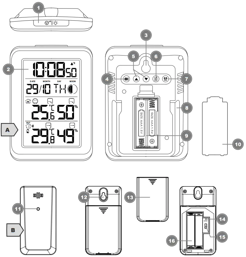
Illustration 1: All parts of the base station (top) and wireless sensor (bottom)
| 1 SNZ/LIGHT button (snooze function /display brightness) | 2 Display (base station) |
| 3 Wall mount fixture | 4 SET button (basic settings) |
| 5 UP button (increase value), DOWN button (decrease value) | 6 CH button (channel selection) |
| 7 ALARM button | 8 Stand |
| 9 Battery compartment | 10 Battery compartment cover |
| 11 Function indicator | 12 Wall mount fixture |
| 13 Battery compartment cover | 14 RESET knob (reset all settings) |
| 15 Slide control for channel selection | 16 Battery compartment |
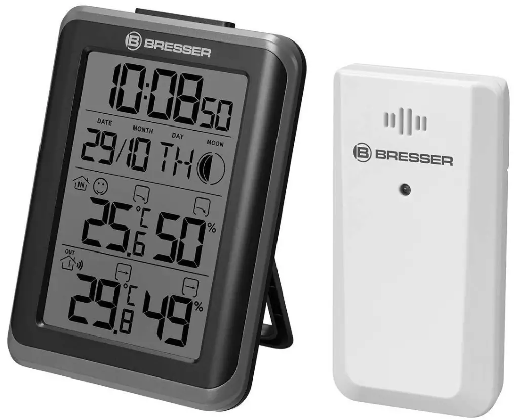
Scope of delivery:Art. No. 7000012 CM3/GYE: Weather station (A) (1 piece), Thermo-/Hygrosensor (B) (1 piece)Art. No. 7000013: Weather station (A) (2 pieces), Thermo-/Hygrosensor (B) (3 pieces)Also required (not included):Station: 2 pcs. each Micro batteries (1.5V, type AAA/LR03)Sensor: 2 pcs. each Micro batteries (1.5V, type AAA/LR03)
Screen display
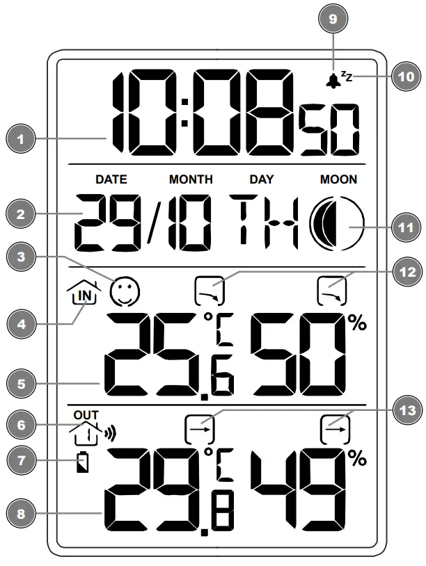
| 1 Current time | 2 Date, day and month |
| 3 Comfort indicator (climate) | 4 Indoor info icon |
| 5 Temperature and humidity | 6 Outdoor sensor info icon |
| 7 Low battery indicator | 8 Outdoor temperature and humidity |
| 9 Symbol for enabled alarm | 10 Alarm interruption (snooze) activated |
| 11 Moon phase | 12 Trend arrows indoor |
| 13 Trend arrows outdoor |
Before commissioning
NOTICE![]() Avoid connection faults!In order to avoid connection problems between the devices, the following points must be observed during commissioning.
Avoid connection faults!In order to avoid connection problems between the devices, the following points must be observed during commissioning.
- Place the base unit (receiver) and sensor (transmitter) as close together as possible.
- Connect the power supply to the base unit and wait until the indoor temperature is displayed.
- Establish power supply for the sensor.
- Set up/operate the base unit and sensor within the effective transmission range.
- Make sure that the base unit and the radio sensor are set to the same channel.
When changing the batteries, always remove the batteries in both the base unit and the sensor and reinsert them in the correct order so that the radio connection can be re-established. If one of the two devices is operated via a mains power connection, the power connection for this device must also be disconnected briefly when changing the battery. If, for example, only the batteries in the sensor are replaced, the signal cannot be received or can no longer be received correctly.Note that the actual range depends on the building materials used in the building and the position of the base unit and outdoor sensor. External influences (various radio transmitters and other sources of interference) can greatly reduce the possible range. In such cases, we recommend finding other locations for both the base unit and the outdoor sensor. Sometimes a shift of just a few centimeters is enough!
Setting up power supply
Base unit
- Remove the battery compartment cover.
- Insert the batteries into the battery compartment. Ensure that the battery polarity (+/-) is correct.
- Replace the battery compartment cover.
- Wait until the indoor temperature is displayed on the base station.Remote sensor
- Remove the battery compartment cover.
- Insert the batteries into the battery compartment. Ensure that the battery polarity (+/-) is correct.
- Move the CH slide control to the position for the desired transmission channel (setting CH1, CH2 or CH3 with screen display).
- Replace the battery compartment cover.NOTICE! When operating one outdoor sensor, channel 1 is recommended as the default setting.
Manual time setting
- Press the SET button for approx. 4 seconds to enter the time setting mode.
- Digits to be set are flashing.
- Press UP or DOWN button to change the value.
- Press the SET button to confirm and switch to the next setting.
- Sequence of the settings: Year > Month > Day > Language > 12-/24-hour mode > Hours > Minutes
- Finally, press the SET button to save the settings and exit settings mode.
Alarm setting
- Press and hold ALARM button for approx. 2 seconds to enter the alarm time setting mode.
- Digits to be set are flashing.
- Press UP or DOWN button to change the value.
- Press ALARM button to confirm and continue to the next setting.
- Settings order: Hours > Minutes
- Finally press the ALARM button to save the settings and exit the setting mode.
- Press ALARM button in normal display mode to display the alarm time.
- Press UP button to activate the alarm. The symbol will be displayed. The alarm is activated.
- Press UP button again to disable the alarm. The symbol will not be displayed. The alarm is disabled.
Snooze function
- When the alarm sounds, press the SNZ/LIGHT button to activate the snooze function. The alarm sounds again after 5 minutes.
- When the alarm sounds, press any other key to stop the alarm until the set alarm time is reached again.
Moon phases
In the Northern hemisphere, the moon waxes (the part of the moon we see that glows after New Moon) from the right. This is because the side of the moon illuminated by the sun moves from right to left in the northern hemisphere. In the southern hemisphere, however, it moves from left to right. Thetwo tables below show the representations of the moon phases.
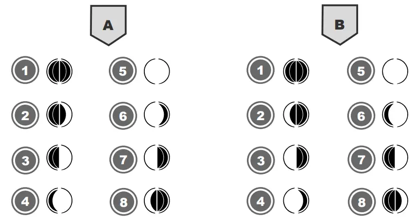
Illustration 2: (A) northern hemisphere, (B) southern hemisphere
| 1 New Moon | 2 Waxing Crescent |
| 3 First quarter | 4 Waxing Gibbous |
| 5 Full Moon | 6 Waning Gibbous |
| 7 Last quarter | 8 Waning Crescent |
Connecting remote sensors
The Weather Station can display the readings from up to 3 wireless sensors* of the same type. Each radio sensor must be set to a separate channel. Proceed as follows to set the channel:
- Remove the battery compartment cover of the wireless sensor.
- Set the channel selection switch to the desired channel (CH1, CH2 or CH3).
- Re-attach the battery compartment cover.
- NOTICE! Each connected wireless sensor must be set to a different channel. If only one wireless sensor is connected, it should be set toCH1.
- Press the CHANNEL button on the base station several times to display the measured values for the individual channels. The selected channel is shown in the display.
- Press CHANNEL button for about 3 seconds to reset the values and search for a wireless sensor (RF signal).
*further wireless sensors are optionally available
Temperature display
In normal display mode, press the DOWN key to toggle between °C and °F.
MAX/MIN Weather data
The base station stores the maximum and minimum readings for indoor and outdoor temperature as well as for the humidity:1. Press the UP button repeatedly to display the stored values of the main unit and of the currently set wireless sensor one after another.2. Display sequence: Maximum values > Minimum values > Current values3. When a stored value is displayed, press the UP button for about 3 seconds to delete the value.
Technical data
Base unit
| Batteries | 2x AAA, 1.5 V |
| Maximum number of sensors | 3 |
| Temperature unit | °C/°F |
| Temperature measuring range | -0°C – 50°C (32°F to 122°F) |
| Humidity measuring range | 20% to 95% (RH) |
| Time format | 12 or 24 hours |
| Dimensions | 80 x 110 x 22 mm (W x H x D) |
| Weight | 100 g (without batteries) 123 g (with batteries) |
Wireless sensor
| Batteries | 2x AAA, 1.5 V |
| Transmission frequency | 433 MHz |
| RF transmission range | 30 m |
| Maximum RF power | under 10mW |
| Temperature unit | °C/°F |
| Temperature measuring range | -40°C to 70°C (-40°F to 158°F) |
| Humidity measuring range | 20% to 95% (RH) |
| Dimensions | 50 x 93 x 25 mm (W x H x D) |
| Weight | 47 g (without batteries) 70 g (with batteries) |
EC declaration of conformity

A “Declaration of conformity” in accordance with the applicable directives and corresponding standards has been prepared by Bresser GmbH. The full text of the EC declaration of conformity is available at the following Internet address: www.bresser.de/download/70000120000007000013/CE/7000012000000_7000013_CE.pdf
UKCA Declaration of Conformity
 Bresser GmbH has issued a “Declaration of Conformity” in accordance with applicable guidelines and corresponding standards. The full text of the UKCA declaration of conformity is available at the following internet address:www.bresser.de/download/70000120000007000013/UKCA/7000012000000_7000013_UKCA.pdfBresser UK Ltd. • Suite 3G, Eden House, Enterprise Way, Edenbridge, Kent TN8 6Hf, Great Britain
Disposal
![]() Dispose of the packaging materials properly, according to their type, such as paper or cardboard. Contact your local waste disposal service or environmental authority for information on the proper disposal.
Dispose of the packaging materials properly, according to their type, such as paper or cardboard. Contact your local waste disposal service or environmental authority for information on the proper disposal.
![]() Do not dispose of electronic devices in the household garbage!According to the European Directive 2012/19/EU on Waste Electrical and Electronic Equipment and its transposition into national law, used electrical equipment must be collected separately and recycled in an environmentally sound manner.
Do not dispose of electronic devices in the household garbage!According to the European Directive 2012/19/EU on Waste Electrical and Electronic Equipment and its transposition into national law, used electrical equipment must be collected separately and recycled in an environmentally sound manner.
![]() Batteries and rechargeable batteries must not be disposed of with household waste. You are legally obliged to return used batteries and accumulators and can return the batteries after use either in our sales outlet or in the immediate vicinity (e.g. in the trade or in municipal collection points) free of charge.
Batteries and rechargeable batteries must not be disposed of with household waste. You are legally obliged to return used batteries and accumulators and can return the batteries after use either in our sales outlet or in the immediate vicinity (e.g. in the trade or in municipal collection points) free of charge.
Batteries and accumulators are marked with a crossed-out dustbin and the chemical symbol of the pollutant, “Cd” stands for cadmium, “Hg” stands for mercury and “Pb” stands for lead.

Please contact the service centre first for any questions regarding the product or claims, preferably by e-mail.e-mail: [email protected]Telephone*: +44 1342 837 098BRESSER UK LtdCustomer SupportSuite G3, Eden HouseEnterprise WayEdenbridge, Kent TN8 6HFUnited Kingdom* Number charged at local rates in the UK (the amount you will be charged per phone call will depend on the tariff of your phone provider); calls from abroad will involve higher costs.
 report this ad
![]()
Contact46414 Rhede · Germanywww.bresser.de@BresserEurope
References
Bresser | BRESSER ClimaTemp IO Funkthermometer Jumbo Set | Expand Your Horizon
IBERIA.COM en United States – the best prices for Iberia flights
bresser.de/warranty_terms
index · powered by h5ai 0.26.1 (http://larsjung.de/h5ai/)
Bresser | BRESSER MyClimate Thermo- / Hygrometer Uhr | Expand Your Horizon
Bresser | Startseite | Expand Your Horizon mit BRESSER
[xyz-ips snippet=”download-snippet”]