
Weather Station
Instruction manual
Visit our website via the following QR Code or web link to find further information on this product or the available translations of these instructions. www.bresser.de/P7002420
WARRANTY
![]()
- Imprint (German)Bresser GmbHGutenbergstr. 246414 RhedeGermanyhttp://www.bresser.deFor any warranty claims or service enquiries, please refer to the information on “Warranty” and “Service” in this documentation. We apologize for any inconvenience caused by the fact that we cannot process enquiries or submissions sent directly to the manufacturer’s address.Errors and technical changes excepted.© 2020 Bresser GmbHAll rights reserved.The reproduction of this documentation – even in extracts – in any form (e.g. photocopy, print, etc.) aswell as the use and distribution by means of electronic systems (e.g. image file, website, etc.) withoutthe prior written permission of the manufacturer is prohibited.The designations and brand names of the respective companies used in this documentation are generally protected by trade, trademark and/or patent law in Germany, the European Union and/or other countries.
- Validity noteThis documentation is valid for the products with the following article numbers:7002420Manual version: 1220Manual designation:Manual_7002420_ClimaTemp-XXL_de-en-fr-nl-es_BRESSER_v122020aAlways provide information when requesting service.
- About this Instruction Manual
 NOTICEThese operating instructions are to be considered a component of the device.Read the safety instructions and the operating manual carefully before using this device.Keep this instruction manual in a safe place for future reference. When the device is sold or given to someone else, the instruction manual must be provided to the new owner/user of the product.
 - General safety instructionsDANGERRisk of an electric shock!This device contains electronic parts that are powered by a power source (AC adapter and/or batteries). Improper use of this product may result in electric shock. Electric shock can cause serious or fatal injuries. It is therefore imperative that you observe the following safety information.• Never leave children unattended when handling the device! Follow the instructions carefully and do not attempt to power this device with anything other than power sources recommended in this instruction manual, otherwise, there is a danger of an electric shock!DANGERExplosion hazard!Improper use of this product may result in fire. It is essential that you observe the following safety information in order to avoid fires.• Do not expose the device to high temperatures. Use only the recommended batteries. Do not short-circuit the device or batteries, or throw them into a fire! Excessive heat or improper handling could trigger a short-circuit, a fire or an explosion!NOTICE Danger of material damage!Improper handling may result in damage to the unit and/or accessories. Therefore, use the device onlyin accordance with the following safety information.• Do not disassemble the device! In the event of a defect, please contact your dealer. They will contact the Service Center and can arrange the return of this device for repair if necessary.• Do not immerse the unit in the water!• Do not expose the device to impacts, vibrations, dust, constant high temperatures or excessive humidity. This can result in malfunctions, short-circuits, or damage to the batteries and components.• Use only the recommended batteries. Always replace weak or empty batteries with a new, complete set of batteries at full capacity. Do not use batteries from different brands or types or with different capacities. Remove batteries from the device if it is not to be used for a longer period of time!NOTICERisk of voltage damage!The manufacturer is not liable for damage related to improperly installed batteries!
Parts overview Base station
![]()
Illustration 1: All parts of the base station
- Housing
- Display
- Indoor sensor
- MODE/SET button (change display mode or settings)
- DOWN/RAIN HISTORY button (decrease value or show 30 days precipitation history)
- UP/RCC/ALARM button (increase the value or enable alarm)
- RAIN SINCE/CLEAR button (show precipitation since last reset or delete stored precipitation values)
- Wall mount fixture
- WEATHER/ABS/REL button (set weather or change barometric pressure type)
- RESET button (reset all settings)
- Stand, fold-out Battery compartment cover
- Battery compartment
- RAIN ALERT button (set and enable precipitation alert)
- OUT-TEMP ALERT button (set and enable outdoor temperature alert)
Parts overview Multisensor Set
![]()
Illustration 2: Multisensor Set: Thermo-hygrometer (top left) and windmeter/rain gauge (right)
| 1 Wall mount fixture3 Display5 °C/°F button (display change between °C or °F)7 Battery compartment9 Battery compartment cover11 Wind cups13 Connection cable with modular plug15 Mounting shoe17 Tube clamps19 Modular plug for connection to the modular socket on theBasestation | 2 Signal transmission indicator4 Housing6 RESET button (reset all settings)8 Modular socket10 Wind vane12 Rain gauge14 Mounting tube (several parts)16 Fixing screws18 Mounting screws and nuts |
Scope of delivery
Base unit (A), thermo-hygrometer (B), windmeter/rain gauge (C), connection cable (D), mounting utensils (E)Also required (not included):Station: 2 pcs. Mignon batteries (1.5V, AA type)Sensor: 3 pcs. Mignon batteries (1.5V, AA type)Small Phillips screwdriver
Screen display
![]() Illustration 3: Screen display of the base station
Illustration 3: Screen display of the base station
| 1 AM/PM information in 12-hour time mode3 Beaufort scale for wind forceclassification(1 to 12)5 Wind speed in km/h7 Windchill (in °C or °F)9 Daily precipitation (24 hours) (in MM)11 Outdoor temperature (in °C or °F)13 Humidity indoors (in %)15 Wind direction17 Symbol for barometric pressure tendency(rising, steady or falling)19 Weather forecast21 Current time (seconds) or weekday oralarm time (display depends on the selected displaymode)23 Moon phase | 2 Current time (hours:minutes:seconds)4 Outdoor sensor symbol (when measurement values aredisplayed)6 Wind gust8 Total precipitation (30 days) (in MM)10 Indoor temperature (in °C or °F)12 Humidity outdoors (in %)14 Higheset/lowest value for outdoor temperature (24 hourshistory)16 Barometric pressure type (ABS = absoluteor REL = relative)18 Barometric pressure value (in MB/HPA)20 Symbol for radio signal22 Symbol for active alarm |
Before commissioning
![]() NOTICEAvoid connection faults!In order to avoid connection problems between the devices, the following points must be observed during commissioning.
NOTICEAvoid connection faults!In order to avoid connection problems between the devices, the following points must be observed during commissioning.
- Place the base unit (receiver) and sensor (transmitter) as close together as possible.
- Connect the power supply to the base unit and wait until the indoor temperature is displayed.
- Establish power supply for the sensor.
- Set up/operate the base unit and sensor within the effective transmission range.
- Make sure that the base unit and the radio sensor are set to the same channel.When changing the batteries, always remove the batteries in both the base unit and the sensor andreinsert them in the correct order so that the radio connection can be re-established. If one of the two devices is operated via a mains power connection, the power connection for this device must also be disconnected briefly when changing the battery. If, for example, only the batteries in the sensor are replaced, the signal cannot be received or can no longer be receivedcorrectly.Note that the actual range depends on the building materials used in the building and the position of the base unit and outdoor sensor. External influences (various radio transmitters and other sources of interference) can greatly reduce the possible range. In such cases, we recommend finding other locations for both the base unit and the outdoor sensor. Sometimes a shift of just a few centimeters is enough!
Setting up power supply
Base unit
- Remove the battery compartment cover.
- Insert the batteries into the battery compartment. Ensure that the battery polarity (+/-) is correct.
- Replace the battery compartment cover. Thermo-Hygrometer
- Remove the battery compartment cover.
- Insert the batteries into the battery compartment. Ensure that the battery polarity (+/-) is correct.
- Replace the battery compartment cover.
NOTICE! The power supply of the wind / rain gauge is ensured via the cable connection to the thermo-hygrometer. (For more information, see the chapter ‘Installing the multisensor set’)
Installing the multisensor set
![]()
Illustration 4: Mounting example
- Assemble the individual parts of the mounting tube.
- Carefully run the connection cable from the windmeter/rain gauge through the mounting tube and the mounting shoe.
- Insert one end of the mounting tube into the opening below the windmeter/rain gauge and the other end into the opening of the mounting shoe.CAUTION! Make sure that the cable is not being damaged when inserting the tube!
- Attach the windmeter/rain gauge and the mounting shoe to the mounting tube with the fixing screws through the drill holes.
- Attach the mounting shoe to a horizontally and vertically aligned pole or a wall with the enclosed mounting material in at least 2 meters height.
- Remove the battery compartment cover of the thermo-hygrosensor.
- Insert the modular plug on the other end of the cable into the modular socket of the thermo-hydro sensor.CAUTION! Before inserting or removing the modular plug, press down the locking lug!
- Mount the thermo-hygrosensor below the windmeter/rain gauge.
Automatic time setting
After the power supply was established, the clock will automatically search for the radio signal. Theclock will automatically search for the radio signal.If the radio signal is received correctly, the date and time will be set automatically and the radio control signal icon turns on.If the clock fails to receive the time signal, go ahead with the following steps:1. Press DOWN/RAIN HISTORY button and UP/RCC/ALARM button for approx. 2 seconds to re-initiate radio signal reception.2. If the device is still not receiving the signal, the time must be set manually.Read the detailed manual for more information about manual time settings and other user-defined settings (see download information on page 2).
Manual time setting and other user defined settings
- In normal display mode, press MODE/SET button for approx. 3 seconds to switch to settings mode.
- Digits to be set are flashing.
- Press DOWN/RAIN HISTORY button or UP/RCC/ALARM button to change the value.
- Press the MODE/SET button to confirm the setting and move to the next setting.
- Settings order: 12/24 hours mode > RCC on/off > time zone (-12 to +12 hours) > hours > minutes > seconds > year > month > day > language > temperature unit > barometric pressure unit > wind speed unit > precipitation unit > wind direction
- Finally, press MODE/SET button to save the settings and exit settings mode.
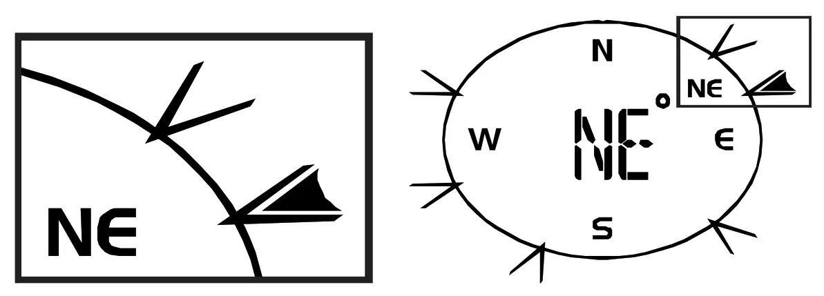
Setting the wind direction
To adjust the wind direction, proceed as follows:
- Press the MODE/SET button for approx. 3 seconds to enter the settings mode.
- Press the MODE/SET button repeatedly until the wind direction setting is shown in the display at the end (all directions flash).
- Align the wind vane with the wind turbine in a northerly direction (tip points north).
- Press the UP/RCC/ALARM or DOWN/RAIN HISTORY button to set the wind direction indicator on the display to North.
- Press the MODE/SET button to confirm the setting.
Time zone setting
To set a different time zone, proceed as follows:
- Press and hold MODE button for approx. 3 seconds to change to time setting mode.
- Press the MODE button multiple times until the display shows the time offset 00 Hr.
- Press UP or DOWN button to select the desired time deviation in hours (-23 up to +23 hours).
- Finally press the MODE button to save the settings and exit the setting mode.
Display change
In normal display mode, press the DOWN/RCC button to toggle the time display between 12-hour or24-hour mode (AM/PM time information is displayed or hidden accordingly)In normal display mode, press the UP/CF button to toggle between °C and °F when displaying the temperature unit.In normal display mode, press the CH button several times to display channels 1, 2, 3 or automatically alternating one after another.NOTICE! The display of values for different channels requires the connection of several suitable wireless sensors (not included).In normal display mode, press the ALERT button several times to display the set temperature alarm values one after another.
Alarm setting
- Press MODE button to switch to alarm time display.
- Press and hold ALARM button for approx. 2 seconds to enter the alarm time setting mode (AL).
- Digits to be set are flashing.
- Press UP or DOWN button to change the value.
- Press ALARM button to confirm and continue to the next setting.
- Settings order: Hours > Minutes
- Finally press the ALARM button to save the settings and exit the setting mode. Alarm will be activated automatically. Thesymbol will be displayed.
- Press MODE button in normal display mode to display the alarm time.
- Press ALARM button during the alarm time display to disable the alarm. The symbol will not be displayed.
Temperature alarm setting
- In normal time display mode, press DOWN button for approx. 2 seconds to enter temperature alarm time setting mode.
- Digits to be set are flashing.
- Settings order: ON/OFF (Temperature alarm on/off) > Temperature highest limit > Temperature lowest limit > Exit
- Press UP or DOWN button to change the value.
- Press SET button to confirm and continue to the next setting.
- The temperature settings mode will be quit automatically after 30 seconds of inactivity. All settings done before will be saved.
- When outdoor temperature reaches a highest or lowest limit, the temperature alarm symbol will flashand an alarm will sound for approx. 3 seonds. This will be repeated with an interval of 1 minute until the temperature has fallen below the limit again.
NOTICE! NOTICE! Select temperature alarm OFF from the temperature settings mode to disable the temperature alarmpermanently.
Receiving measurements automatically
Once batteries are installed, the base station will display the measurement readings. Readings from the remote sensor will be displayed within 3 minutes after powering it on.
Temperature alarm setting
- In normal time display mode, press DOWN button for approx. 2 seconds to enter temperaturealarm time setting mode.
- Digits to be set are flashing.
- Settings order: ON/OFF (Temperature alarm on/off) > Temperature highest limit > Temperature lowest limit > Exit
- Press UP or DOWN button to change the value.
- Press SET button to confirm and continue to the next setting.
- The temperature settings mode will be quit automatically after 30 seconds of inactivity. All settingsdone before will be saved.
- When outdoor temperature reaches highest or lowest limit, the temperature alarm symbol will flashand an alarm will sound for approx. 3 seonds. This will be repeated with an interval of 1 minute until the temperature has fallen below the limit again.NOTICE! NOTICE! Select temperature alarm OFF from the temperature settings mode to disabled the temperature alarmpermanently.PrecipitationThe precipitation which was collected over a certain period is displayed on the base station in millimeters or inches and is based on the current precipitation rate.Select display modePress the RAIN button several times until the desired time range is displayed:RATECurrent precipitation rate in the past hourDAILYTotal precipitation rate of the current day, measured from midnightWEEKLYTotal precipitation rate of the current weekMONTHLYTotal precipitation rate of the current month
Select measurement unit (millimeters or inch)
- Press the RAIN button for approx. 3 seconds to change to measurement unit settings.
- Press UP or DOWN button to change between mm (millimeters) and in (inch).
- Finally press the RAIN button to save the settings and exit the setting mode.NOTICE! Readings are updated automatically every 6 minutes.
Set weather status and air pressure above N.N
NOTICE! For a correct display of the weather forecast, the current weather status and the air pressure above N.N. must be set correctly immediately after commissioning. The first weather forecast will be displayed approximately 6 hours after the set-up.NOTICE! These settings should also be made again when chnaging the location of the unit.
- After switching on the unit, press the WEATHER/ABS/REL button for 3 seconds. The weather symbol on the display flashes.
- Select the graphic symbol corresponding with the current weather status by pressing the UP or DOWN button.
- Press WEATHER/ABS/REL button to enter the next setting. The air pressure value flashes.
- Set the current value for the air pressure above N.N. by pressing the UP or DOWN key.
- NOTICE! Information on the current value for the air pressure above N.N. can be found on the Internet at https://www.dwd.de/DE/leistungen/beobachtung/beobachtung.html
- Finally, press the WEATHER/ABS/REL button to save the settings and return to the normal display mode
Weather trend
The weather station will calculate a weather trend for the next 12 hours on basis of the measured values.
 Illustration 5: Weather trend indicators
- Sunny
- Partly cloudy
- Cloudy
- Rain
- Snow
Barometric / Atmospheric PressureAtmospheric Pressure is the pressure at any location on earth, caused by the weight of the column ofair above it. One atmospheric pressure refers to the average pressure and gradually decreases as altitude increases. Meteorologists use barometers to measure atmospheric pressure. Since variation in atmospheric pressure is greatly affected by weather, it is possible to forecast the weather by measuring the changes in pressure.
- Press the BARO button to enter the setting mode.
- Press the BARO button again, to change the unit between inHg / mmHg / hPa.
- Press the BARO button for 3 seconds to change between absolute and relative atmospheric pressure.• ABSOLUTE: the absolute atmospheric pressure of your location.• RELATIVE: the relative atmospheric pressure based on the sea level.Set relative atmospheric pressure value
- Get the atmospheric pressure data of the sea level (it is also the relative atmospheric pressure data of your home area) through the local weather service, internet and other channels.
- Hold the BARO button for approx. 3 seconds, until ABSOLUTE or RELATIVE flashes.
- Press the UP or DOWN button to switch to RELATIVE mode.
- Press the BARO button again, and the number for RELATIVE flashes.
- Press UP or DOWN button to change the value.
- Press the BARO button to save and exit the setting mode.NOTE
- The default relative atmospheric pressure value is 1013 mb/hPa (29.91 inHg), which refers to the average atmospheric pressure.
- When you change the relative atmospheric pressure value, the weather indicators will change along with it.
- The built-in barometer can notice the environmental absolute atmospheric pressure changes. Based on the data collected, it can predict the weather conditions in the forthcoming 12 hours. Therefore, the weather indicators will change according to the detected absolute atmospheric pressure after you operate the clock for 1 hour.
- The relative atmospheric pressure is based on the sea level, but it will change with the absolute atmospheric pressure changes after operating the clock for 1 hour.
Wind speed and direction
Reading the wind direction
| Wind direction indicator | Meaning |
| Real-time wind direction | |
|
Wind directions appeared in the last 5 minutes (max. 6) |
 Select display modePress the WIND button several times until the desired rate is displayed:• AVERAGE: average of all wind speed numbers recorded in the previous 30 seconds• GUST: highest wind speed (gust) recorded from last reading
The wind level provides a quick reference on the wind condition and is indicated by a series of text icons:
| Wind level | LIGHT | MODERATE | STRONG | STORM |
| Speed | 1 – 19 km/h | 20 – 49 km/h | 50 – 88 km/h | > 88 km/h |
Select wind speed unit
- Press the WIND button for approx. 3 seconds to enter the setting mode.
- Press the UP or DOWN button to change the unit between mph (miles per hour), m/s (miles per second), km/h (kilometer per hour) or knots.
- Press the WIND button to save the settings and exit the setting mode.
Wind chill factorThe wind chill factor is shown in the “WIND CHILL” field on the display.Note:The wind chill factor is based on the common effects of temperature and wind speed.The displayed wind chill is calculated solely from temperature and wind speed and is measured by the outdoor sensor.
EC declaration of conformityHereby Bresser GmbH declares that the radio equipment type with 7002420 complies with Directive2014/53/EU. The full text of the EC declaration of conformity is available at the following Internet addresswww.bresser.de/download/7002420/CE/7002420_CE.pdf
Disposal
Dispose of the packaging materials properly, according to their types, such as paper or cardboard. Contact your local waste disposal service or environmental authority for information on the proper disposal.![]() Do not dispose of electronic devices in the household garbage!According to the European Directive 2012/19/EU on Waste Electrical and Electronic Equipment and its transposition into national law, used electrical equipment must be collected separately and recycled in an environmentally sound manner.
Do not dispose of electronic devices in the household garbage!According to the European Directive 2012/19/EU on Waste Electrical and Electronic Equipment and its transposition into national law, used electrical equipment must be collected separately and recycled in an environmentally sound manner.![]()
 report this ad
ContactBresser GmbHGutenbergstraße 246414 Rhede · Germanywww.bresser.de![]() @BresserEurope
@BresserEurope
References
[xyz-ips snippet=”download-snippet”]