MCe 9.0-21
MCe 9.0-21PORTABLE AIR CONDITIONER.PRODUCT MANUAL.
WARNINGS

These instructions should be read by:The specifying engineer.The installation engineer.The user.The service engineer.

- Failure to follow these instructions may result in risk of personal injury or damage to the equipment.
- Damage due to a failure to follow these instructions will invalidate the warranty.
- The appliance must be serviced by qualified engineers in compliance with local regulations.
- The appliance must be switched off and disconnected from the power supply before any work is carried out.
- There are no user controls inside the appliance casing.
- Do not place anything on top of the appliance.
- An air gap of at least 300mm should be allowed at the front and rear of the unit to ensure a clear airflow.
- Do not disconnect the appliance from the supply under load.
- For internal use only. Do not use out of doors.
- Exhaust fan liable to start without notice.
- Extension cables should be correctly rated for the load,fully unwound and never run through water or over sharp edges.
- Always transport and store in an upright position.
- Maximum operating temperature 35°C.
- Minimum operating temperature 15°C.
Specifications:
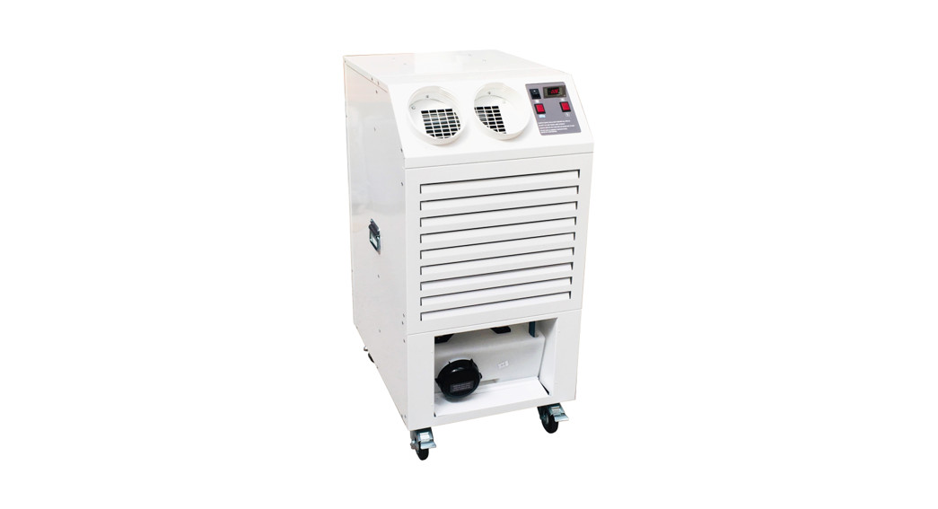
The MCe9.0 is a Mono-block portable air conditioning unit.It is connected to a 13 Amp. 230Vac. 50Hz power supply and comes fitted with a fused uk moulded plug.It is recommended that the supply to the machine should be protected by a 30mA RCD
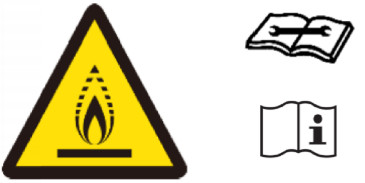 This appliance contains an A2L refrigerant classified as mildly flammable.Always read the user and service manual before operation.The minimal charge within the appliance does not require a minimum room size for safe operation.
WARNING.Do not use means to accelerate the defrosting process or to clean, other than those recommended by the manufacturer.The appliance shall be stored in a room without continuously operating ignition sources (for example:open flames, an operating gas appliance or an operating electric heater.Do not pierce or burn.Be aware that refrigerants may not contain an odour.
| TECHNICAL SPECIFICATIONS. MCe9.0-21 | |
| Cooling capacity. | 8.31 kw |
| Power supply. | 230v. 1P. 50Hz. 13A UK plug. |
| Running current at 35 degrees /40% humidity. | 10.3A |
| Refrigerant. | R454C. 1300g |
| Weight main cooling unit | 95 kg |
| Maximum permissible refrigerant pressure. | 370 psi |
| Main cooling unit noise level. | 65 dB(A) |
| Main unit evaporator airflow. Maximum. | 1080 m3/h |
| Main unit condenser airflow. Maximum. | 1800 ms/h |
| Minimum operating temperature. | 15 °C |
| Maximum operating temperature. | 35 °C |
| IP rating. | IP2X |
| Dimensions HfVV/D | 1192/526/774mm (Including spigot) |
| GWP | <150 |
Set up and operation:
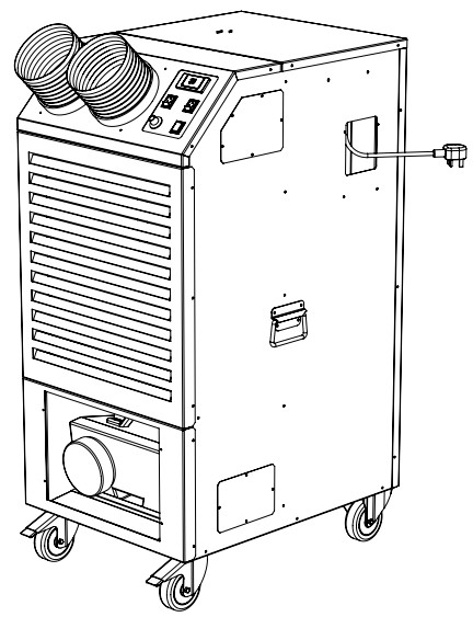
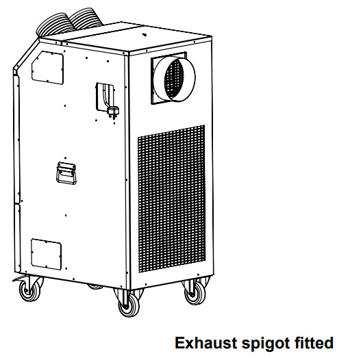
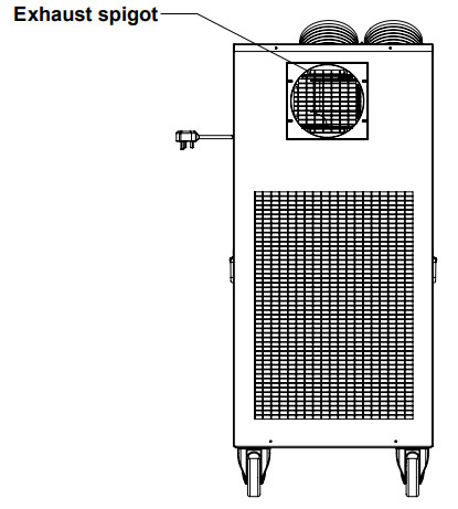
To prevent transport damage the appliance is shipped with the rear exhaust spigot supplied loose.The rear exhaust spigot must be fitted before use.Tools required: No2 PZ screwdriver.
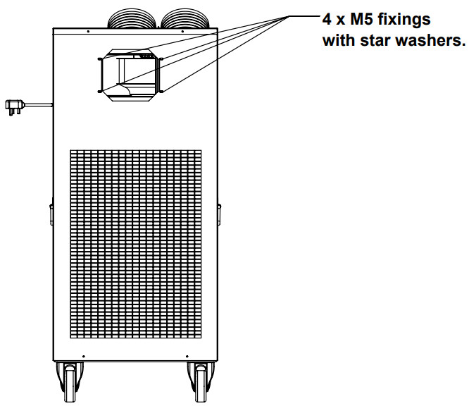
- Remove the 4 x M5 fixings with star washers at the rear of the machine.
- Use these fixings to secure the exhaust spigot in place. Pinch tight. Ensure the star washers are refitted.
Set up and operation cont’d:
- The unit is designed to operate between 15’C and 35t. Operation outside of these temperatures could cause compressor failure and will Invalidate the warranty. If the temperature In the room is above 35t it is recommended that all the doors and windows are opened and the unit run on Fan only to reduce the temperature.
- The appliance is fitted with a frost prevention system that controls the condenser fan. The fan will switch in and out depending on the temperature of the system. Warning! The fan is liable to start without notice.
- Site the unit on a firm level surface and apply the castor brakes. Do not operate the machine without engaging the castor brakes.
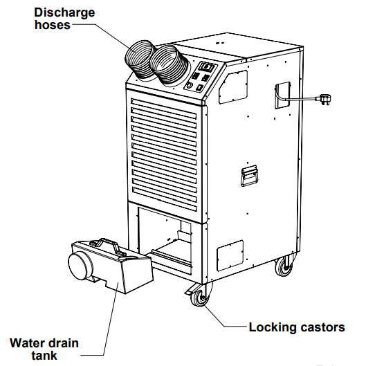
- Attach the 200mm exhaust duct and route to a suitable discharge point. Keep the duct as short and straight as possible. Do not operate the unit if the hose is kinked or punctured. Do not exceed the supplied length of the exhaust duct.
- Should cold air need to be directed to a particular area fit the air discharge hoses to the front outlets and extend to the desired discharge points.
- Do not exceed 1.25M per hose.
- Check that the water drain tank is correctly located In it’s housing and the flexible drain hose is inserted into the tank.
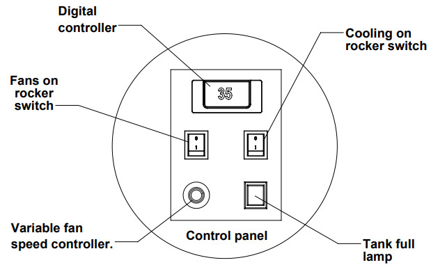
- Conned the unit to a 230Vac 50Hz power supply. Turn the ‘Fan On’ switch to ‘I’ to start the fans.
- Turn the tooling On’ switch to ‘I’ to start the compressor. It should be noted that the compressor will not start if the fan switch is not in the on position or the ambient temperature is below 15•C. The compressor is fitted with a start delay timer and will not run for 3 minutes from activation of the cooling switch. This device Is designed to protect the compressor from repeated start-stop cycles.
- Set the digital thermostat to the desired temperature (This is the ‘set point’). During normal running, the digital thermostat read-out shows the ambient temperature of the room. (See P6 for setting the digital thermostat)
- Set the variable fan speed controller to the desired speed. Allow a minimum of 10 minutes for the unit to start cooling.
- During the cooling process, the unit will produce condensate (water) which will drain into the water drain tank. Once this tank fills to a set level it will switch the compressor and fans off and illuminate the ‘Tank Full’ lamp.
- Before removing the water drain tank, and to avoid any potentially damaging water spillage, switch the fans and cooling off and allow 5 minutes for any accumulated moisture within the machine to drain into the tank.
- To empty the tank carefully remove it from the machine using the grab handle on the top by lifting and sliding it forwards. Do not loosen or remove the large screw cap on the front of the tank. Once the tank is emptied replace it in the housing ensuring It Is correctly located and that the flexible drain hose is inserted into the tank.
- The machine can now be restarted.
- Ensure the water drain tank is empty prior to transportation.
- Do not remove the water drain tank while the machine is operating.
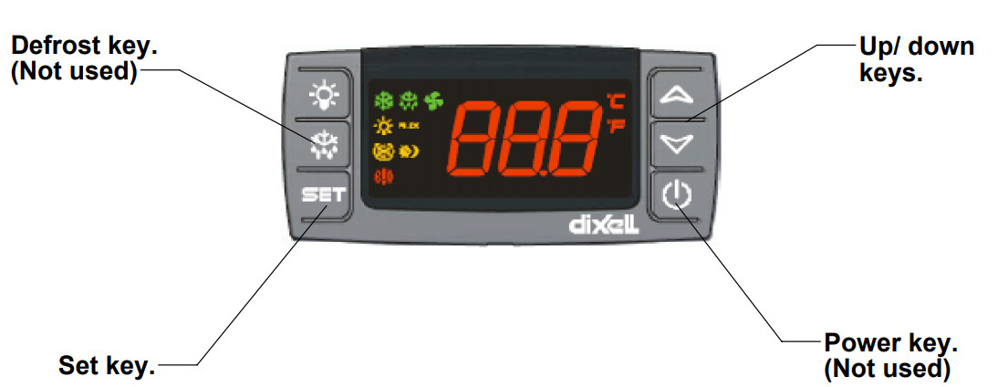
Setting the digital thermostat:
How to see the set point:
- To see the set-point push and immediately release the SET key: the display will
- The setpoint is the minimum temperature the air-conditioner will operate down to.show the set point value.
- Push and immediately release the SET key or wait for 5 seconds to display the ambient room temperature.
How to change the set point:
- Push the SET key for more than 2 seconds to change the setpoint value.
- The appliance comes factory set at 15º C.
- The value of the setpoint will be displayed and the ” C” LED starts blinking.
- To change the setpoint value push the up or down arrows within 10 seconds.
- The minimum set point is 15º C.
- To memorise the new setpoint value push the SET key or wait for 10 seconds.
Operation and controls:
Maintenance and upkeep:Maintenance and service work should only be carried out by competent technicians with experience and qualifications in the handling of A2L refrigerants.The appliance should always be disconnected from the power supply before any work is carried out.Before maintenance work is carried out all technicians should:a) Carry out safety checks to ensure the risk of ignition is minimised.b) Operate with controlled procedures to minimise the risk of flammable gas or vapour being present while work is carried out.c) Ensure all staff in the local area are instructed in the nature of the work being carried out.d) Not work in confined spaces.e) Check work areas with an appropriate leak detector prior to and during work to minimise the risk of flammable atmospheres.f) If any hot work is being carried out an appropriate fire extinguisher should be available to hand. Either Co2 or dry powder.g) All possible ignition sources should be kept sufficiently far away from the work area.h) Adequate ventilation shall be provided when breaking into the refrigeration system. The ventilation should safely disperse any released refrigerant to the external atmosphere.i) When replacing electrical components only spare parts specified by the manufacturer shall be used.j) Electrical work should be preceded with initial safety checks:i) All capacitors need to be discharged in a manner that avoids sparks.ii) No live electical components or wiring should be exposed while charging, recovering or purging the system.iii) There is continuity of earth bonding.k) Under no circumstances should potential sources of ignition be used in the searching for or detection of refrigerant leaks.l) On discovery of a leak all refrigerant should be removed before a repair is carried out. The manufacturer recommends purging the circuit with an inert gas before brazing.m) Before charging ensure the refrigeration system is earthed.
Routine checks:
- Check and clean the evaporator and condenser heat exchanger coils. Build-up of dust and dirt can severly affect the performance of the machine. Remove the front and rear panels and clean with compressed air.
- Periodically check the water tank drain mechanism is operating correctly and the drain hose is present and in good condition.
- Regularly inspect the mains cable and plug for signs of damage or wear. Do not operate the machine with a damaged mains cable.
- Check that the castors are running freely and that the breaking mechanisms are working correctly.
Troubleshooting guide:
| PROBLEM | POSSIBLE CAUSE | SOLUTION |
| The machine fails to operate | Power Failure | Check unit is connected to the power supply. |
| Check plug fuse for failure and correct 13A rating. | ||
| Check Building circuit is not overloaded. | ||
| Poor cooling performance. | ‘Tank Full’ lamp illuminated | Empty water tank. |
| Cooling not selected | Switch cooling on | |
| Digital controller set below ambient temperature. | Check to set on the digital controller. | |
| Coils dirtyFilters dirty. (where fitted) | Clean coils. See Maintenance. | |
| Clean filters. See maintenance. | ||
| Exhaust hose too long or kinked. Exhaust outlet restricted or blocked. | Ensure maximum duct length is not exceeded. Ensure duct is run as straight as possible and is venting correctly at it’s exit point. | |
| Air inlet grills obstructed | Remove obstruction. | |
| Water leaking. | Clogged drain hose. | Remove blockage. |
| Water drain tank missing | Replace tank | |
| Tank full and tank mechanism not working correctly. | Check tank mechanism operates correctly. Ensure the ‘Tank Full’ lamp illuminates when the mechanism is activated. | |
| The drain hose is not correctly located in the tank. | Ensure the drain hose is located inside the tank. | |
| The compressor stops working. | Input voltage too low. Water drain tank full. | Check line voltage.Check water drain tank is not full. |
Exploded view:
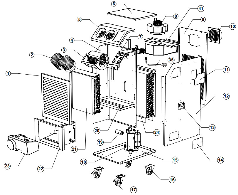
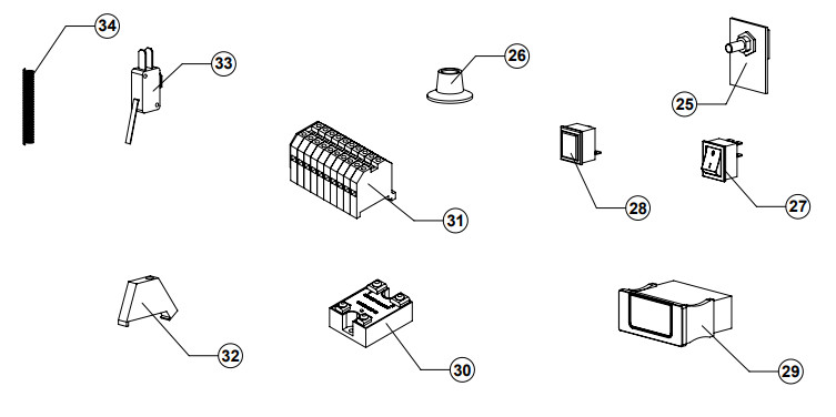
Spare Parts:
| ITEM No | PART No | DESCRIPTION | PRICE |
| 1 | BW010620 | FRONT TOP PANEL | POA |
| 2 | BW030201 | 1500 DUCT CM PLASTIC COLLAR | POA |
| 3 | FA010319 | 148 EC FAN MOTOR | POA |
| 4 | BW010409 | LEFT SIDE PANEL | POA |
| 5 | BW010213 | TOP FRONT PANEL | POA |
| 6 | BW010214 | TOP REAR PANEL | POA |
| 7 | BW040516 | CENTRE DIVIDE PANEL | POA |
| 8 | FA010208 | 280mm CONDENSER FAN | POA |
| 9 | BW010707 | REAR PANEL | POA |
| 10 | BW010921 | OUTLET SPIGOT ASSEMBLY | POA |
| 11 | BW040124 | TOP ACCESS PLATE | POA |
| 12 | BW010312 | RIGHT SIDE PANEL | POA |
| 13 | ME040305 | TRUNK HANDLE | POA |
| 14 | BW040125 | LOWER ACCESS PLATE | POA |
| 15 | BW011003 | BASE PANEL | POA |
| 16 | ME010211 | 100mm FIXED CASTOR | POA |
| 17 | ME010212 | 100mm SWIVEL CASTOR | POA |
| 18 | FR010125 | COMPRESSOR | POA |
| 19 | EL030316 | CAPACITOR 45uf | POA |
| 20 | BW040517 | DRIPTRAY | POA |
| 21 | FR030116 | EVAPORATOR COIL | POA |
| 22 | BW010621 | LOWER FRONT PANEL | POA |
| 23 | ME040137 | CONDENSATE TANK | POA |
| 24 | FR030219 | CONDENSER COIL | POA |
| 26 | EL030145 | SPEED CONTROLLER | POA |
| 26 | EL040137 | SPEED CONTROLLER KNOB | POA |
| 27 | EL030109 | 071 ROCKER SWITCH | POA |
| 28 | EL030704 | INDICATOR LAMP | POA |
| 29 | EL030408 | DIGITAL CONTROLLER XR30 | POA |
| 30 | EL030215 | 40A SOLID STATE RELAY | POA |
| 31 | EL020424 | TERMINAL ASSEMBLY. 8mm. | POA |
| 32 | EL020403 | DIN RAIL END STOP | POA |
| 33 | EL030205 | MICROSWITCH (New Rapid pan No: 78-0702) | POA |
| 34 | ME040626 | SPRING | POA |
| 35 | EL020108 | MAINS CABLE | POA |
| 36 | EL020426 | TERMINAL CROSSLINK (Not shown) | POA |
| 37 | BW030442 | FASCIA LABEL (Not shown) | POA |
| 38 | FR020101 | 378 COPPER PIPE (Not shown) | POA |
| 39 | FR020308 | 20g FILTER DRIER (Not shown) | POA |
| 40 | FR010302 | 318 INSULATION TUBE (Not shown) | POA |
| 41 | BW040518 | GALV CONDENSER FAN HOUSING | POA |
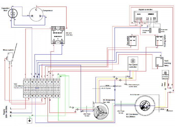
MCe 9.0-21 Wiring diagram
[xyz-ips snippet=”download-snippet”]