

Owner’s Manual
 The lightning flash with arrowhead symbol within an equilateral triangle, is intended to alert the user to the presence of un-insulated “dangerous voltage “ within the product’s enclosure that may be of sufficient magnitude to constitute a risk of electric shock to persons.
 The exclamation point within an equilateral triangle is intended to alert the user to the presence of important operating and maintenance (servicing) instructions in the literature accompanying the product.
- Read these instructions.
- Keep these instructions.
- Heed all warnings.
- Follow all instructions.
- Do not use this apparatus near water.
- Clean only with dry cloth.
- Do not block any ventilation openings. Install in accordance with the manufacturer’s instructions.
- Do not install near any heat sources such as radiators, heat registers, stoves, or other apparatus (including amplifiers) that produce heat.
- Do not defeat the safety purpose of the polarized or grounding-type plug. A polarized plug has two blades with one wider than the other. A grounding type plug has two blades and a third grounding prong. The wide blade or the third prong are provided for your safety. If the provided plug does not fit into your outlet, consult an electrician for replacement of the obsolete outlet.
- Protect the power cord from being walked on or pinched particularly at plugs, convenience receptacles, and the point where they exit from the apparatus.
- Only use attachments/accessories specified by the manufacturer.
- Caution: unit weighs in excess of 65 lbs / 29.5 kgs. Please always use two persons to lift and carry the device.
 Use only with the cart, stand, tripod, bracket, or table specified by the manufacturer, or sold with the apparatus. When a cart is used use caution when moving the cart/apparatus combination to avoid injury from tip-over.
- Any terminals marked with the preceding symbol are HAZARDOUS LIVE and any wiring connected to these terminals must be installed by an INSTRUCTED PERSON or with ready-made leads or cords.
- Unplug this apparatus during lightning storms or when unused for long periods of time.
- Refer all servicing to qualified service personnel. Servicing is required when the apparatus has been damaged in any way, such as power-supply cord or plug is damaged, liquid has been spilled or objects have fallen into the apparatus, the apparatus has been exposed to rain or moisture, does not operate normally, or has been dropped. NO USER SERVICEABLE PARTS INSIDE
 Use only with the cart, stand, tripod, bracket, or table specified by the manufacturer, or sold with the apparatus. When a cart is used use caution when moving the cart/apparatus combination to avoid injury from tip-over.
 Any terminals marked with the preceding symbol are HAZARDOUS LIVE and any wiring connected to these terminals must be installed by an INSTRUCTED PERSON or with ready-made leads or cords.
WARNING: TO REDUCE THE RISK OF FIRE OR ELECTRIC SHOCK, DO NOT EXPOSE THIS APPARATUS TO RAIN OR MOISTURE. DO NOT EXPOSE THIS EQUIPMENT TO DRIPPING OR SPLASHING AND ENSURE THAT NO OBJECTS FILLED WITH LIQUIDS, SUCH AS VASES, ARE PLACED ON THE EQUIPMENT. TO COMPLETELY DISCONNECT THIS EQUIPMENT FROM THE AC MAINS, DISCONNECT THE POWER SUPPLY CORD PLUG FROM THE AC RECEPTACLE. THE MAINS PLUG OF THE POWER SUPPLY CORD SHALL REMAIN READILY OPERABLE.
_____________________________________
BRYSTON LIMITED WARRANTY
Bryston analog audio products are warranted to be free from manufacturing defects for twenty (20) years from the original date of manufacture. The warranty includes parts and labour. Bryston digital products and cables are warranted for five years from the original date of manufacture. The warranty includes parts and labour.
Bryston products having motorized moving parts, excluding motorized volume controls, are warranted for three years from the original date of manufacture. The warranty includes parts and labour.
Bryston will remedy the problem by repair or replacement, as we deem necessary, to restore the product to full performance. Bryston will pay return shipping only for the full length of the specific product’s warranty.
In the event of a defect or malfunction, contact Bryston’s repair centers for return authorization. Products must be returned using original packaging material only. Packing material may be purchased from Bryston if necessary. This warranty is considered void if the defect, malfunction or failure of the product or any component part was caused by damage (not resulting from a defect or malfunction) or abuse while in the possession of the customer. Tampering by persons other than factory authorized service personnel or failure to fully comply with Bryston operating instructions voids the warranty. This warranty gives you specific legal rights and you may also have other rights which may vary from province to province and country to country. As of 2006-02-22 Bryston will only warranty Bryston products purchased through authorized Bryston dealers. Bryston products with a date code of 0608 or higher (date code format is “yyww”, where “yy” is the two least significant digits of the year and “ww” is the week of the year) must be accompanied by a copy of the bill-of-sale from a Bryston authorized dealer to qualify for warranty service. The warranty is transferable from the original owner to a subsequent owner as long as a copy of the bill-of-sale from the original authorized Bryston dealer accompanies the re-sale. The copy of the bill of sale to any subsequent owner need ONLY include the Name of the Bryston Authorized Dealer and the Model and Serial number of the Bryston product The warranty will only be honored in the country of the original purchase unless otherwise pre-authorized by Bryston.
BRYSTON SERVICE in CANADA:
Postal address: P.O. BOX 2170, Stn. Main PETERBOROUGH, ONTARIO CANADA K9J 7Y4Courier address: 677 NEAL DRIVE PETERBOROUGH, ONTARIO CANADA K9J 6X7PHONE: 705-742-5325 FAX: 705-742-0882E-mail:
BRYSTON SERVICE in the USA:
79 COVENTRY ST., Suite 5 NEWPORT, VERMONT U.S.A. 05855-2100PHONE: 802-334-1201FAX: 802-334-6658E-mail:
BRYSTON SERVICE outside Canada and the USA:
contact your local distributor orCHECK OUR WEB SITE: www.bryston.comE-MAIL BRYSTON DIRECTLY: FAX BRYSTON DIRECTLY: 01-705-742-0882PHONE BRYSTON DIRECTLY: 01-705-742-5325
Welcome
Thank you for your purchase of a Bryston 9B3 (Cubed) amplifier! Decades of ongoing research and development have produced our highest performing amplifiers yet. Our customers are a tremendous resource to whom we look for a measure of success. Please feel welcome to contact us with feedback and suggestions.
Description
The 9B3 is modular multi-channel audio power amplifier available in 3, 4, or 5 channel versions with each channels capable of 200 watts. Robust yet beautiful machined aluminum enclosures house our proprietary industry-leading circuit designs resulting in exemplary performance observed both in the listening space and in the laboratory.
C-Series variants are available in your choice of 17 inch or 19 inch wide non-rack mountable aluminum dress panels anodized in clear (silver toned) or black. 19 wide C-Series amplifiers include front handles. PRO amplifiers feature 19 inch wide rack mountable dress panels with handles in a black anodized front finish and also include individual channel trims located on the rear panel. All versions include rear panel handles.
Features
Bryston 9B3 includes the following features:
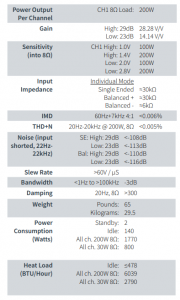
- Switchable gain: 23dB or 29dB
- Balanced XLR input. Pin 2 positive.
- Single ended (RCA) input.
- SoftStart circuitry for managing inrush current upon initial power up.
- Wired remote control AC/DC trigger input and passthrough with supplied connector.
- Network connected control and information.
Shipping Box and Packing Material
Please keep the original shipping box and all packing material. This will ensure the amplifier is protected in future transport. In the unlikely event you have a problem and must return it for service,you must use the proper packing material. Ship the amplifier only in the original packing material, as the unit is not insurable by carriers otherwise. Replacement packing materials consisting of a shipping carton with plastic foam inserts is available from Bryston for a small fee.
Ventilation
Bryston has deliberately chosen to omit fans from our amplifiers in an effort to minimize the noise level in your listening environment. Instead, we use only passive heat sinks which are fully capable of maintaining a safe operating temperature of the amplifier even under loud playback conditions. For them to work most effectively, air must be permitted to pass freely through the heat sink fins and around the amplifier. Maintain a minimum of 3.5 inches of space to each side, top and back of the amplifier when in use. Do not stack the amplifiers immediately on top of one another in an enclosed cabinet. If you must stack the amps, you may need to utilize fans or another active cooling mechanism to ensure uninterrupted operation. If you repeatedly experience channels shutting down due to heat, rearrange the amplifiers to have more surrounding free space, or employ an active cooling solution. Never operate the amplifier in a vertical position.
Connecting to A/C Power
Please check the Data Plate on the rear of the amplifier adjacent to power entry module to verify power requirements agree with your location. See “12. Data Plate:” on page 9. Before plugging in the power cord, make sure the Master Circuit Breaker (“7. Master Circuit Breaker:” on page 9) is switched to the ‘ON’ position. Plug the IEC-320 C14 end of the power cord into the amplifier, then plug the other end into an approved and grounded A/C receptacle. The STATUS LED should flash green, then switch to red indicating A/C power is present in the unit. See “10. Power Status Indicator:” on page 9. The amplifier is now ready to be powered on.
Connecting to Loudspeakers
Connection to loudspeakers is accomplished by attaching high quality speaker cable to the Output Binding Posts (see “Rear Panel” on page 8) per the following instructions.
The RED binding post is connected to the positive channel output. Connect this post to the (+) terminal on the loudspeaker.
The BLACK binding post is connected to the negative output. Connect this post to the (-) terminal on the loudspeaker.
Never connect either binding post to a ground!
The output binding posts provide three different interconnect options. Combinations may be used when bi-wiring. Cables should be kept as short as practical and should never be terminated with connectors that may become confused for AC power connectors. Cables should be dressed away from input and power cables.
Banana plugs offer a quick disconnect option. Before inserting a banana plug into the binding post, be sure to tighten the post nut to avoid rattling and to provide full insertion of the banana plug. Gold plated locking banana plugs are available from Bryston.
Spade lugs provide high contact area and secure fastening. Lugs should be gold plated. Post diameter is 5/16” (8mm ), lug width 5/8” (16 mm). Gold plated spade lugs are available from Bryston.
Stripped bare wire up to 3 gauge can be inserted through the hole in the binding post and held in place by tightening the post knob. Additional tightening pressure can be achieved using a coin in the slots of the knob. Do not over tighten or the binding post may become damaged. Note that copper wire is malleable and may require further tightening after the initial installation.
To prevent the risk of equipment damage or personal harm, use only Class 2 rated loudspeaker wire properly terminated and connected securely to the binding posts.
Connecting Audio Inputs
The Bryston Cubed amplifier can receive analog audio from any preamp or surround processor with volume controlled line-level outputs. Balanced XLR as well as singled ended RCA inputs are both available and can be selected using the Input Select switch on the rear panel of the amplifier.
Balanced vs. Single Ended Input
The balanced input requires a balanced pre-amp source. Balanced systems provide noise rejection from external electrical interference, so cable length can be very long—50 meters or longer. The single ended or unbalanced input is provided for pre-amps without balanced output. Single-ended cables should be kept to 20 feet (6 meters) or less. In general never use longer cables than necessary, never coil excess cable length, and keep signal wires away from AC power or speaker cables.
Power Conditioners
Bryston urges caution in choosing a power conditioner for your audio/video system. Large power amplifiers can draw very substantial current from the wall plug, and many so-called power conditioners can in fact hinder the supply of current by inserting resistances in series with the line cord. However, there are now power conditioners that can reduce or eliminate RF and ‘hash’ from the AC supply and may actually improve current delivery to your system. This type of power conditioner (exemplified by Bryston BIT products) uses the energy storage in a large toroidal transformer to provide high instantaneous power and reduce the substantial AC output resistance of the wall socket and house wiring. This resistance can be in the range of 0.5 to 1 Ohm and is typically reduced to only a few milliohms by the power conditioner. That in turn considerably reduces voltage drop in the power line on high current surges and quite substantially increases the stability of the power line improving audio (and video) focus,precision and clarity.
External Control Voltage
To power-up the amplifier using an external control voltage, supply a 5V to 12V (AC or DC) control voltage to the ‘IN’ terminals of connector (fig. 1). Use paired wire of 22 to 18 gauge between the source device and the Bryston Cubed series amplifier. The appropriate mating connector is a 1/8” tip-sleeve style plug where tip is signal and sleeve is ground.
Set the External Turn-On switch to “External” See “9. Remote Power Up:” on page 9. Place the front panel switch in the ON position. The amplifier will now power-up only when the control voltage is present (on). Immediately following power-up, the control voltage will appear at the ’OUT’ terminals of connector for the control of other equipment. The removal of the control voltage (0v) causes the amplifier to turn ‘off’, and the control voltage at the ‘OUT’ terminals is interrupted.
In the “Local” setting of the External Turn-On switch the amplifier will ignore the control voltage and power up only by using the front panel push-button power switch. If a control voltage is present at the ‘IN’ terminals, it will still be available at the ‘OUT’ terminals after the power-up sequence.
Note:The ‘OUT’ terminals are connected to the ‘IN’ terminals once the amplifier has powered-up.
The control current is determined by the source equipment. The carrying current of the ‘OUT’ relay is 2 amps.
The amplifier’s control circuitry itself draws less than 2 mA from the control current when operating.
9B 3 Amplifier
LED indicators, which are normally red/green, may be red/blue instead. When red/blue LEDs are supplied green is replaced with blue and orange is replaced with magenta in the below descriptions.
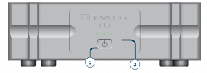
1. Power/Standby Switch:
The front panel features a push-on/push-off type latching power switch used to apply or remove A/C line power to the SoftStart circuitry. Note that the rear circuit breaker must be on for the amplifier to power-up. The front panel button should be on to enable network control.
2. LED Indicator:
Each amplifier channel has a front panel LED indicator to monitor the following conditions:
Unlit Amplifier not powered on (OFF MODE)Red Channel is muted during power up or when channel is muted via software.Green Channel operation is normalFlashing Channel is clipping. Reduce inputRed level!Orange Thermal protection mode
POWER UP SEQUENCE
After pushing the power switch, each channel LED will turn from unlit to red (mute). When the power supplies have stabilized, the channel will come out of mute and the LED will change to green (normal operation).
UNLIT LED (No power)The amplifier channel LED when unlit indicates no A/C mains power is present at the channel power transformer. This usually indicates that the amplifier probably needs only to be powered on.
CLIPPING (flashing red)Clipping occurs when the channel output level no longer can follow the level increase at the input (over driven input condition). When a channel is driven into clipping, the channel LED will change from green to red then back to green when the level is reduced. Momentary clipping can be tolerated, however it indicates that maximum undistorted power has been surpassed and potential speaker damage may result if overload conditions persist. Any amplifier that is constantly operated into clipping indicates a more powerful amplifier is needed for that application.
THERMAL SHUTDOWN (orange)Each channel has thermal shutdown circuitry to prevent damage due to overheating. Should thermal shutdown occur, the channel will mute, and the channel LED will turn orange. When the channel has cooled to a safe operating condition, the channel will return to normal operation. Persistent thermal shutdown indicates steps need to be taken to increase airflow across the channel or channels heat sink. See “Ventilation” on page 4.
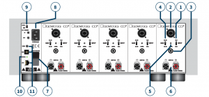
1. Input Select Switch:Select either Balanced or Single Ended audio input.2. Balanced Audio Input:Each channel has a balanced audio input. This input connector accepts standard XLR (pin 1 =Ground, pin 2 =Positive, pin 3 =Negative). Use quality, 100% shielded cables with gold plated connectors.3. Single Ended Audio Input:Each channel has a single ended audio input. This input connector accepts standard ‘RCA’ or ‘Phono’ connectors. Use quality, 100% shielded cables with gold plated connectors.4. Gain Select Switch:The optimum gain setting will depend upon the source pre-amp operating level, and or personal preference. The 29dB setting is used when the source is single-ended or from a transformer coupled balanced source. This is the typical for single ended or un-balanced operation. The 29dB setting provides the most amplifier gain and equates to 100w @ 8 ohms output for a 1V input (noise -115 dB).
The 23dB setting is used when the source output is actively balanced. This is the typical setting for balanced operation. Or use this setting whenever less gain is required. The 23dB setting equates to an output of 100w @ 8 ohms for 2V input.
The noise is referenced in dB below rated output. Different input configurations result in slightly different noise readings. The above noise ratings represent minimum readings. Actual readings may be better.
5. Channel Level Attenuator (PRO ONLY):The level control will attenuate the input signal level from 0dB through -14dB.6. Output Binding Posts:The RED binding post is connected to the positive amplifier output. Connect to this post the (+) terminal on the loudspeaker.
The BLUE or BLACK binding post is connected to the negative output. Connect to this post the (-) terminal on the loudspeaker.
Never connect either binding post to an electrical ground!
The output binding posts provide three different interconnect options: banana plugs, spade lugs, and bare wire. Combinations may be used when bi-wiring. Cables should be kept as short as practical and should never be terminated with connectors that may become confused for AC power connectors. Cables should be dressed away from input and power cables.
Only use Class 2 Rated Wiring. No other wiring is permitted for use.
7. Master Circuit Breaker:
Master Circuit Breaker: The Cubed series amplifier uses a magnetictrip circuit breaker to protect the amplifier. This breaker is not an on off switch and must be in the ‘ON’ position during the installation and normal operation. Use the front panel push-button power switch or an external control voltage to power-up or power-down the amplifier. Should the breaker trip, or switch “OFF”, lower or remove the amplifier input signals. Remove the AC power by disconnecting the power cord from the amplifier for 20 seconds. Switch the breaker to the ‘ON’ position. Reconnect the power cord, then power the unit up normally. The circuit breaker must be ‘ON’ at all times for the Cubed Series amplifier to operate.
8. A/C Power Input:
An IEC-320 C14 power inlet provides for connection of an IEC-320 C13 equipped power cord. Before connecting the power cord to the amplifier, check that the voltage rating on the data plate or ratings label conforms with your locality. With the circuit breaker ‘ON’ insert the power cord into the Cubed series amplifier, then plug the other end to an appropriate A/C outlet.
9. Remote Power Up:When in External position, the Power On state is governed by voltage applied to IN terminals of the Remote Power Up connector. The front panel power switch must remain in the ‘ON’ position. “External Control Voltage” on page 6 for instructions regarding connection and usage.
10. Power Status Indicator:Plugging in the power cord applies power to the amplifier. The status indicator will initially flash green. The number of flashes indicates the revision of the soft start circuit software. This puts the amplifier in Standby mode and the LED turns red indicating power is present. Engaging the front panel on/off switch initializes the startup sequence. During the soft start ramp up operation, the status led will turn orange when connected to 60Hz power or red when connected to 50Hz power. The Status LED switches to green when the ramp up sequence ends then turns off ten seconds later. Turning off the front panel on/off switch returns the amplifier to the Standby mode.
11. RS232 / USB / EthernetConnect the 9B³ to an appropriate control system to view status and control the unit. See “Network Connection” on page 10 for further instructions.
12. Data Plate:Unit specific information is printed here including model number, operating voltage, frequency, and serial number.
9B3 -17-SIL-120~120V 60Hz 1770WSerial No: 9B3-000000Date: 1915 REV:1234
You may connect your 9B³ to your local area network using CAT5 or better cable to facilitate use of the built in web-based user interface or to control and monitor the unit using an automation system. Once connected to the network, you may access the web user interface with a web browser by entering the host name into the address bar. The host name is formatted like so where the last 6 digits are the serial number of your unit: http://9B-000000
Some web browsers and networks ignore NetBIOS names such as above. In this case, you will need to use the numerical IP address of your unit to access the web user interface. You can find the IP address by logging into your network router or with popular network information apps on iOS and Android such as Fing or by going to http://my.bryston.com
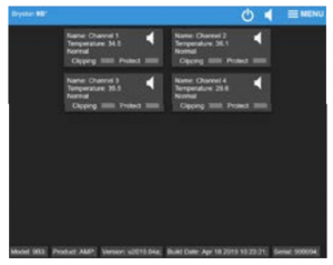
For each installed channel, a rectangular section is shown providing data about that channel including the channel name, current temperature in Celsius, status, and warning lights for clipping and thermal protection. Click the loudspeaker icon in a channel to mute that channel, or click the loudspeaker icon in the blue header to mute all channels simultaneously. Place the unit in standby or toggle out of standby by clicking the power icon in the blue header.
Click or tap and hold a channel to view an event log for that channel or to rename the channel. Log events are expressed Hours:Minutes:Seconds since the log view was opened.

As with many other Bryston products, the 9B³ may receive occasional firmware updates to ensure reliable operation and add new features. Check your installed version and for any new updates by using the MENU on the 9B³ web user interface. Internet connection must be available to show correct information.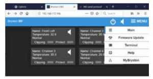
To update the firmware:
- Download the new firmware file by clicking “Click here to download firmware.bin”
- Click “Browse…” or “Choose File” to locate the newly downloaded file on your computer.
- Click Update Firmware to initiate the update procedure. The amplifier will place itself in standby, update firmware, and the amp will reboot into standby. Do not remove power or otherwise interfere with the firmware update procedure.

The 9B³ can be controlled and monitored through a variety of mechanisms including TCP/IP when connected to your local area network, USB, RS232, and DC trigger.
Serial Protocol
The 9B³ can receive commands and can send responses to each command. It can also (optionally) broadcast automatic responses to certain system events such as front panel button presses. Commands can be sent over RS232, RS485 (with an RS232 to RS485 interface) and TCP/IP using HTTP cmd.cgi.
The RS232 input is a 3.5mm mini-jack configured as:
Tip TransmitRing ReceiveSleeve Ground
Command Format
| RS232 | # | 8 | D2 | C1 | C2 | C3 | C4 | P1 | P2 | … | CR |
| TCP/IP | %23 | 8 | D2 | C1 | C2 | C3 | C4 | P1 | P2 | … | . |
The command format always begins with a command start character.
The next two digits are the Device ID. The first of which is always “8” for 9B³, and the second will be “0” except when using RS232/RS485 in a multi-drop configuration.
Next are C1 through C4 which comprise the command name. These are typically uppercase ASCII letters.
Following the command name are the arguments or parameters for that command. These are two or more ASCII characters.
The command is always terminated with a carriage return character. For RS232, this is ASCII code 13.
TCP/IP commands are terminated with a period (.)Example:#80MPWRQS<CR> command: query power statusResponses are returned in the same format as commands. Note that responses may contain up to 320 characters. All characters preceding the # or %23 and following <CR> or . are ignored. Do not insert #, spaces, <LF>, <TAB> or other non-ASCII characters inside the command string.
| %2380GETDQS. | list all parameter names |
| %2380GETDxxx. | display decimal value of a parameter named xxx |
| %2380GETHxxx. | display hex value of a parameter named xxx |
| %2380GETSxxx | display text value of a parameter named xxx |
| %2380INFOQS. | list system information in 15 lines: |
| 01 | Product Name |
| 02 | Serial Number |
| 03 | Manufacture Date |
| 04 | Firmware Version |
| 05 | Bootloader Version |
| 06 | Non-volatile Flash1 mem ID |
| 06 | Non-volatile Flash2 memID |
| 08 | Non-volatile user config EEPROM ID |
| 09 | Temperature Sensor ID |
| 10 | Microcontroller CPU ID |
| 11 | Main system board rev. |
| 12 | Ethernet chip ID |
| 13 | MAC address |
| 14 | NETbios name |
| 15 | Current IP address |
| %2380INITQS. | |
| %2380INIT?. | |
| %2380INITnn. | |
| 00 | redefault user configuration (EEPROM) |
| 01 | erase Web GUI files (Flash1) |
| 02 | redefault USB file system (Flash2) |
| 03 | force reprogram using hex file in Flash1 |
| 04 | force reprogram using hex file in Flash2 |
| T1 | calibrate all modules T offsets to ambient |
| fa | clear GUI files and redefault all parameters to factory |
| fb | erase & blank-out all non-volatile memory |
| 222 | unlock & allow execution of the above options note: 00 does not need unlocking! |
| %2380IPADQS. | Returns current IP address |
| %2380LEDSQS. | display channel LEDs status as 4 char string each char representing color: r=red,y=yellow,g=green,0=of |
| %2380LISTQS. | (or ?) list command options |
| %2380LISTnn. | nn are command options: |
| 00 | list Web GUI and other files in Flash1 |
| 01 | list backup Web GUI and other backup files in Flash1 |
| 02 | list FAT12 master boot rec & partition in Flash2 (USB) |
| 03 | list FAT12 file directory in Flash2 (USB) |
| 04 | verify uploaded user hex file in Flash1 |
| 05 | verify factory backup hex file in Flash1 |
| %2380MPWRQS. | display power status (00=standby,01=ON) |
| %2380MPWR00. | power off (front power key must be on or remote sw must be set if enabled, or else no effect!) |
| %2380MPWR01. | power on (front power key must be on and the unit must have been switched off remotely prior to issuing this command. |
| %2380MMUTQS. | display status of mute or unmute as string ggabcde where gg is the global mute status gg=00
if any of the channel is unmuted, gg==01 if all channels are muted. abcde flags mute status of channels 1..5, respectively. Flag codes are M,U or X where M=muted, U=unmuted, X=uninstalled |
| %2380MMUTnn. | mute(01) or global unmute(00) all channels |
| %2380MMUTxn. | mute or unmute selected channel, x=M(mute) or x=U(unmute), n=channel number 1..5 |
| %2380STATQS. | display the status and alert flags of the unit encoded as string of 5 characters, one per each channel module: |
| 1 | module is in normal powered up state |
| t | presently overheated |
| T | was overheated in the recent past (past 60 sec.) |
| m | Muted |
| c | presently clipping |
| C | was clipping recently (past 60 sec.) |
| x | module is not installed, fuse blown or status unknown |
| 0 | in standby and front power switch is of |
| s | in standby by remote, power switch is on |
| B | breaker open and power button is on (all modules |
| b | breaker open and power button is off (all modules) |
| %2380TEMPQS. | display 5 channel temperatures (in C) followed by the temperature of the system board. 6 groups of 6 characters are returned as follows: TEMP sxx.x sxx.x sxx.x sxx.x sxx.x sxx.x |
| %2380TRIGQS. | display signal detected by the external trigger 00=no signal, 01=12V signal detected |
| %2380TRIG00. | disable external trigger output port |
| %2380TRIG01. | enable external trigger output port (default) |
| %2380____ aaa. | null command, no action. Any character string aaa (up to 128 chars) may serves as a comment |
| COMMANDS SENT THROUGH RS232: Commands format is the same as above except the prefix %23 is replaced by # and the end character . (dot) is replaced by carriage return (\r = code 13), for example #80INFOQS\r | |
| Special Diagnostic Commands. No end . or \r needed). Must first unlock by sending #80INIT222. or %2380INIT222. INIT223 to lock. | |
| ? | Display help text |
| .A | clear all overtemp and clipping alerts |
| .a | display overtemp and clipping alerts |
| .c | clear all error messages |
| .C | clear terminal window |
| .e | display error messages |
| .E | close terminal window |
| .r | Reboot |
| .S | dump all system parameters |
| .t | special test |
| .i | display current IP address |
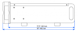
Dimensions
17” C Series 19” C Series (includes front handles)

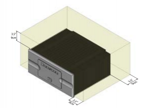
Minimum recommended clearance for heat dissipation
Bryston Limited | 677 Neal Drive | Peterborough, Ontario K9J 6X7 CanadaPhone: 705-742-5325 | www.bryston.com
References
[xyz-ips snippet=”download-snippet”]