
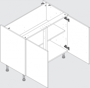
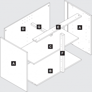
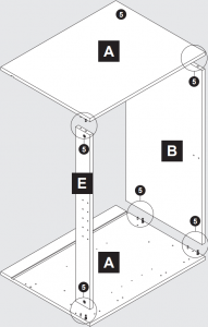
800, 900 and 1000 Base and Corner Base Unit Assembly
TH Note: If fitting a “True Handleless” kitchen, some components will differ to those shown in this instruction and will also be packaged separately. Please refer to your True Handleless guide to Receiving for further details on the different components and difference in installation.
Components
Important Information – True Handleless Kitchens Installers: See Note Above TH

Caution: Some pieces of hardware could be hazardous to small children. Keep all these items out of reach and do not leave children unattended in the assembly area.
Please read these instructions carefully before proceeding. Refer to the Guide to Receiving and Installing your Kitchen booklet for further information.Note: Due to variation in wall conditions no screws are supplied for fixing the units to the wall. If in doubt consult an expert. Assemble the unit on a clean solid work surface.In the interest of continuing improvements we reserve the right to amend or adjust the specifications without prior notice. Errors and omissions excepted.These units may be fitted with a drawer system. The drawers are supplied separately. These instructions show the runner positions for the drawer system.Follow the instructions supplied with the drawers for drawerbox assembly.Every effort has been made to ensure that this product leaves the factory in perfect condition. In the unlikely event that an item is damaged or incorrect, please contact the customer services department.
Note – Fitting Handles: (1) Decide where you are going to position each handle to maintain symmetry around your kitchen. (2) Measure the handle centres and mark off each door/drawer position. (3) Drill through the door/drawer using a fine drill (<2.5 mm), then drill back from the rear face using a 4.5 mm drill. (4) Attach with the fixings provided with your handle.
Ref. No. Item Quantity
150101 ![]() 3.5x12mm 14150202
3.5x12mm 14150202 ![]() 4x12mm 16150201
4x12mm 16150201 ![]() 4x15mm 16/20150199
4x15mm 16/20150199 ![]() 4.5x45mm 4150198
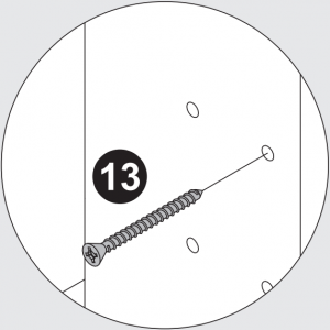
4.5x45mm 4150198 ![]() 55mm Carcase Screw 3154082
55mm Carcase Screw 3154082 ![]() 6154084
6154084  1154085
  7154004
 ![]() 8154027
8154027  6154068
  8154047
  2152181
  4152162
  4150308
 ![]() 2150309
2150309 ![]() 2152401
2152401  4/5152418
  4/5152402
  2152148
  4151999
 ![]() 12151500
12151500  2
2
Tools Required

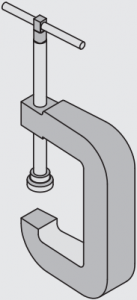
Drill G-Clamp (pair)

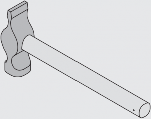
Medium Crosshead Screwdriver Hammer

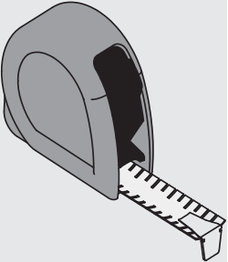
Large Flathead Screwdriver Tape Measure
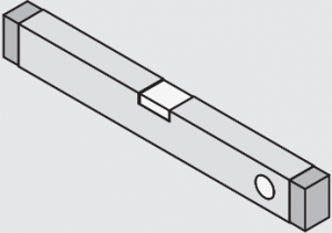
Spirit Level Bradawl
1 – 2 Assembly Instructions
TH Modification required at this stage, see True Handleless guide for further details.
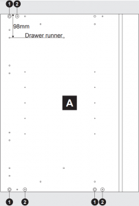
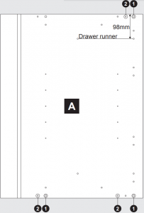
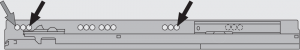
Drawer Runner
![]() 1 x ‘L’; 1 x ‘R’
1 x ‘L’; 1 x ‘R’
![]() x4
x4
 x2
x2
Fit as third screw

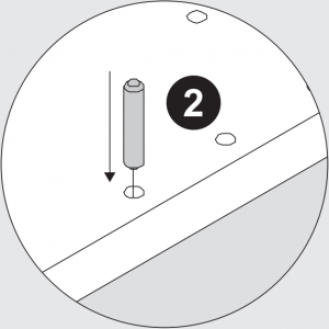
1. ![]() 2.
2. ![]()
154082 6 154004 6
3 – 4
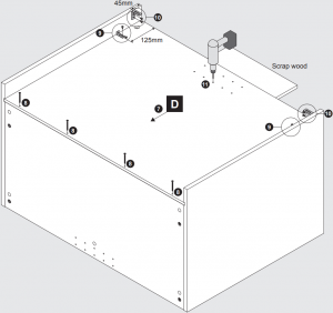
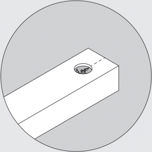
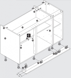
Note: Drill centre holes of B and E for Base Units. For Corner Base Units consult kitchen plan for door size and drill accordingly.
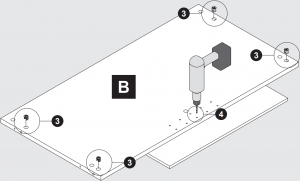
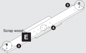
Scrap wood Scrap wood
![]()
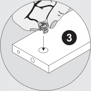
3.
154085 6
5 – 6
TH Modification required at this stage, see True Handleless guide for further details.

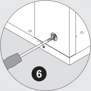
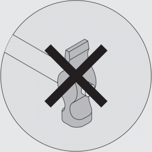
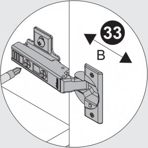
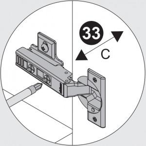
Do Not Over Tighten

Start Locked
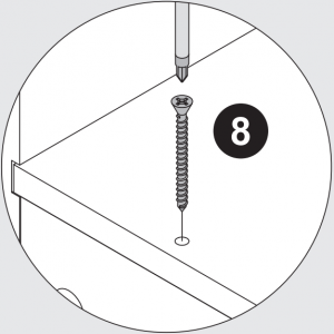
7 – 11
Scrap wood
8.
![]()
150199 4
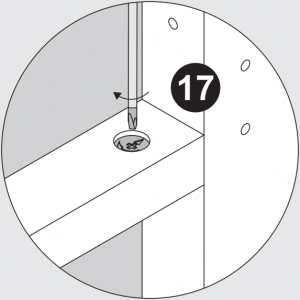
 Note: Countersunk screw goes into back panel D.
 Note: Countersunk screw goes into back panel D.
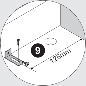
9.
![]()
150101 2 150202 2 154068 2
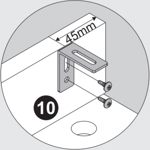
10.
150202 4 154047 2
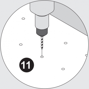
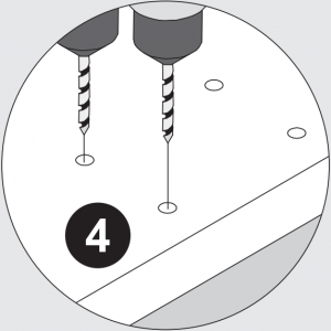
Note: Only drill if drawers are being fit. Base Units drill as indicated. Corner Base Units consult kitchen plan for door size and drill accordingly. Only drill from the lower set of holes
12 – 13 Without Drawers

TH Modification required at this stage, see True Handleless guide for further details.
12.
![]()

154004 2
13.
![]()
150198 2
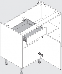
14 – 15 With Drawers
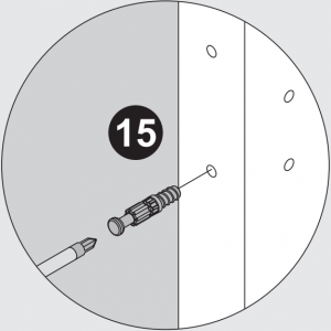
14. 15.
154085 1 154084 1
16 – 17 With Drawers

Do Not Over Tighten
Start Locked
Drawer Runner
![]() 1 x ‘L’; 1 x ‘R’
1 x ‘L’; 1 x ‘R’
![]() x4
x4
x2
Fit as third screw
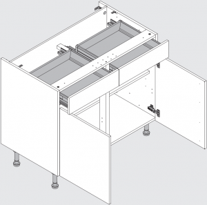
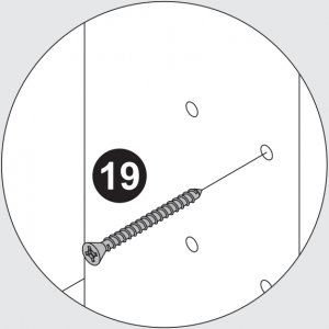
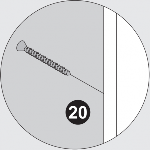
18 – 20 With Drawers
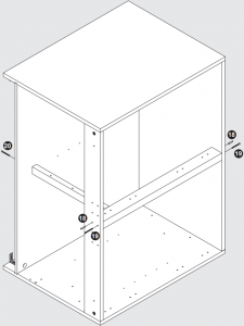
18. 19. 20.
![]()
![]()
![]()
154004 2 150198 2 150198 1

21 – 22
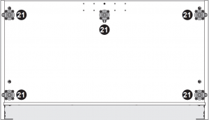

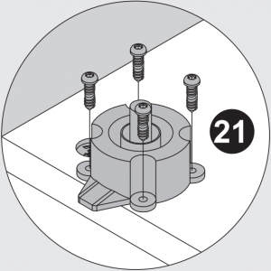
21.

152401 4/800 & 900 5/1000 150201 16/800 & 900 20/1000
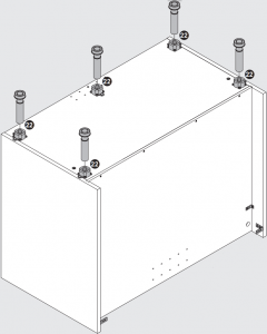
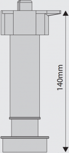
22.
152418 4/800 & 900 5/1000
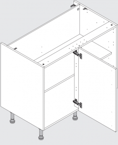
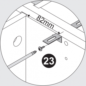
23 – 25 Installation Instructions
23.
150202 2 154068 2
TH Modification required at this stage, see True Handleless guide for further details.
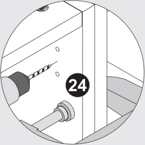
24.
![]()
![]()
150308 2 150309 2

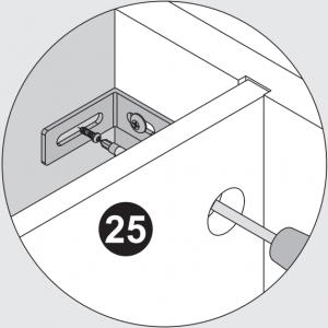
25.
![]()
Appropriate to wall type (Not supplied) 2
26 – 29
26.
151500 2

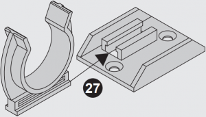
27.
![]()
152402 2 150101 4
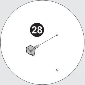
28.
154027 6
30 – 31
Note: Do not over tighten screws or use a power screwdriver.
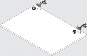 Note: Do not over tighten screws or use a power screwdriver.
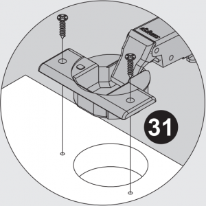
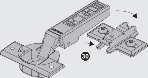
31.
![]()
150101 8
32 – 35
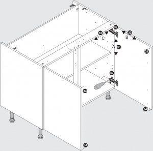
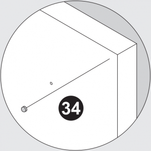
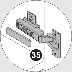
34. 35.

151999 4 152148 4
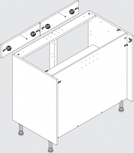
36 – 37 Fixed Fascia Fitting
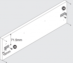
36.
150202 2/4 154068 2/4 151999 4/8
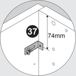
37.
150202 2/4
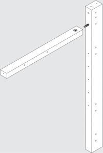
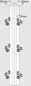
38 Corner Post Fitting
Note: Fittings are packed with the Corner Post.
 Note: Fittings are packed with the Corner Post.
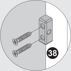

TH Modification required at this stage, see True Handleless guide for further details.
38.
![]()
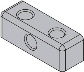
150124 12 154081 6
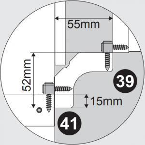
39 – 41 Corner Post Fitting
TH Modification required at this stage, see True Handleless guide for further details.

Note: Fit corner post to adjacent unit, then fit optional blanking panel to corner base unit, finally attached corner post to corner base unit mullion. Use appropriate number of screws (not supplied). Any excess/hangover does not need to be trimmed as it will be concealed in the void.
40. 39. 41.
![]()
![]()
Not Supplied 6-10 150124 6


| Unit Size(mm) | RequiredDoorSize (mm) | Total Lengthin Plan (mm) | Void“x” (mm) |
| 800mm | 300 | 925 | 125 |
| 800mm | 400 | 1025 | 225 |
| 800mm | 500 | 1125 | 325 |
| 1000mm | 400 | 1025 | 25 |
| 1000mm | 500 | 1125 | 125 |
| 1000mm | 600 | 1225 | 225 |
Ref. 170801 (05)
[xyz-ips snippet=”download-snippet”]