Installation Manual forBuderus G115 Direct Vent Oil Boilers115SCIM – 12/06
Save These Instructions!
- The heating boiler must be installed in accordance with local and state codes by a qualified installer.
- Burner start-up must be performed by a qualified service person.
- Explain the operation of the heating unit to the homeowner.
- Keep the manual in a dry place near the boiler.
Notice: This version Nr. BHSG115DV-7 4/04 supersedes all previous manuals. Buderus Hydronic Systems Inc. reserves the right to make changes without notice due to continuing engineering and technological improvements.
Location of Wall Terminals
The location of the wall terminations is one of the most important aspects of a direct-vent installation. Both the intake and exhaust terminations must be located on the same outside wall in order to balance wind pressure that affects the flow of exhaust gases. In addition, the wall terminations shall not be installed on that side of the building exposed to the prevailing wind direction or in alcoves and exterior building recesses where swirling wind conditions may occur.IMPORTANT: Consult with local authorities to ensure compliance with local building, plumbing, and electrical codes.Guidelines For The Location Of The Exhaust Termination.See Figure 2 for details.
- The exhaust terminal must be located such that the products of combustion will be freely dispersed outside without reentering the building. The exhaust gases shall not interfere with people, overheat combustible materials, or enter adjacent buildings.
- The exhaust terminal shall be at least 2 ft from an adjacent building.
- The exhaust terminal shall be at least 7 ft above grade when above public walkways.
- The exhaust terminal shall not be located underneath a porch or crawl space.
- The exhaust terminal shall not be located less than 3 ft from an L-shaped inside building corner and no less than 3 feet away from an outside corner.
- The exhaust terminal shall be located at least 3 ft above any forced air inlet within 10 ft horizontally.
- The exhaust terminal shall not be less than 4 ft below, 1 ft above, or 4 ft horizontally from any door, window or gravity air inlet into the building.
- The exhaust terminal shall be at least 1 ft above grade and placed in such a location where the exhaust terminal is not susceptible to blockage from debris, leaves or falling snow or ice from roofs. A 1/2″ wire-mesh screen at the exhaust terminal must be maintained in good working order.
- The exhaust terminal shall terminate more than 3 ft from any other building opening, oil tank vent, or oil tank fill inlet. (6 ft from any gas service regulator vent outlet).
Guidelines for the location of the intake air terminal:
- The air intake must be placed on the same side of the building as the exhaust to balance wind pressure effects.
- The intake terminal must be at least 1 ft above the maximum local snow level. An outside air intake riser is permitted provided a downturned intake terminal is used (Fig. 1).
- The intake and exhaust terminals must be at least 4 ft apart when using the Aerocowl exhaust termination. This minimum distance can be reduced to 2 ft when the intake terminal is at least 1 ft below the exhaust terminal.
- The intake terminal shall be equipped and maintained with a 1/2″ wire mesh screen in good working order to prevent accidental blockage from the entry of foreign objects.
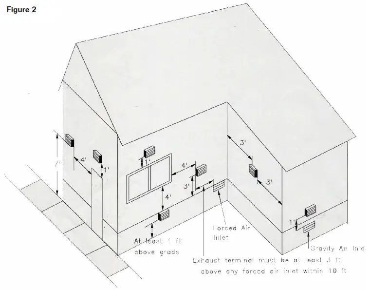
Figure 2: Permissible exhaust termination locations.The venting system is only for a single appliance. Venting of an additional appliance could cause serious injury or loss of life. The venting system shall not be routed into, through, or within any other vent, such as an existing masonry or factory-built chimney. Screens on intake and exhaust terminals must be kept in good working order to prevent debris from entering the venting system.
Sealing of the Vent Piping:
The discharge side of the sealed combustion venting system operates under slight positive pressure. It is of vital importance to seal all flue joints and screw penetrations to prevent leakage of flue gases into the building. Pipe joints and other possible flue gas leak paths should be sealed with high-temperature silicone (500 ºF rated silicone, G.E. 106 or equivalent), or high-temperature tape (360 ºF rated aluminum foil tape, VentureTape 3520CW or equivalent) as necessary.The venting system shall not be pierced under any circumstance after initial installation. Combustion measurements shall be performed at the exhaust termination and/or overfire. The breaching can be pierced for testing as long as the hole is sealed airtight with a bolt, washers, and high temperaturesilicone.
Installation Procedures for Venting System
General Guidelines:
- The oil-fired boiler installation must be performed by a qualified installer in accordance with the regulations put forth in NFPA-31 Installation of Oil-Burning Equipment. The installation must comply with all local codes and authorities having jurisdiction. The installer must have the proper licensing and be experienced with all local codes and regulations.
- Select boiler location and wall termination positions based on required boiler clearances. (See Table 1), the guidelines of pages 3 and 4, compliance with local codes, and on using minimum lengths of the vent pipe.

- Select the point of wall penetration for the exhaust termination based on maintaining a minimum slope of ¼” per foot down towards the termination on the last horizontal pipe section. The wall termination assembly must also slope ¼” per foot down towards the outside. This allows possible condensate to drain from the venting system.
- Slope all other horizontal pipe runs ¼” per foot down towards the boiler vent connection. (Fig. 3).
- Avoid any dips in the venting when using the flexible insulated stainless steel oil vent.Never install a barometric damper into the exhaust piping.
Minimum wall clearance (L1)needed for:
- flex. Stainless Steel oil vent: 24″
- 4″ galvanized pipe: 16″
The Buderus G115 Direct Vent boiler system has been approved for use with two different intake/exhaust options. Follow the guidelines on pages 3 and 4 regarding termination placement.Option 1: Separate air intake hood and Aerocowl exhaust termination. (Part No. AT-4).This system consists of a 4″ air intake hood, a 5″ x 4″ reducer, and a 26½” long, insulated Aerocowl exhaust termination. This termination has a zero clearance rating for combustibles.Option 2: Combination air intake/exhaust termination. (Part No. FT-4).This system consists of a 5″ x 4″ reducer and a zero clearance concentric combination intake/exhaust termination with a 4″ provision for fresh air intake piping.Both exhaust terminations are approved for use with two different exhaust vent pipe options. Always use 4″ galvanized or 4″ flexible metal pipe for fresh air intake for both venting systems.Pipe Option 1: Flexible, insulated 4″ stainless steel oil vent. Maximum length of 10 ft. Oilvent adaptors are supplied. The insulated oil vent is rated for 1″ clearance to combustibles. Wrap the adaptors with 3” of ceramic wool covered with foil tape or sheet metal to maintain 1” clearance.Pipe Option 2: Standard, 26 gauge galvanized vent pipe. The maximum straight length is 6 ft with up to 2 90º elbows. Maintain 18″ clearance to combustibles with the galvanized vent pipe.
Installation Procedures: Exhaust Terminations and Exhaust Vent Piping.
NOTE: Use only the approved materials listed on the previous page for direct venting of oil-fired Buderus G115 boilers. Use of any other materials or systems not installed in accordance with the instructions contained in this manual will void its listing.NOTE: Use strictly high temperature rated silicone (500 ºF rated silicone, G.E. 106 or equivalent) and/or high-temperature tape (360º Frated aluminum foil tape) for sealing at all exhaust pipe joints. Check all seams and joints of the exhaust venting for gas tightness.NOTE: Maintain clearances to combustibles as indicated in Table 1.
Table 1: Boiler and exhaust vent pipe clearances to combustibles
| Front | Side | Rear | Top | Galv. Pipe | Insul. Oil Vent |
| 24″ | 6″ | 6″ | 6″ | 18″ | 1″ |
Option 1: Installation of the Aerocowl termination.
- Cut a 6″ round opening in the outside wall at the selected location. Apply silicone to the backside of the outer faceplate and secure it to the outside wall.
- Insert the Aerocowl termination from the outside up to the outer wall stop. Ensure proper slope.
- Slide the inner plate on the termination up to the inside wall, tighten the gear clamp, and secure the inner plate to the wall.
Option 2: Installation of the concentric termination.
- Cut a square 7″ opening in the outside wall at the selected location. Remove the 4″ air intake collar from the termination assembly.
- Apply silicone to the backside of the wall faceplate. Insert the concentric termination from the outside. Ensure proper slope. Secure the faceplate to the outside wall. Reinstall the 4″ collar.
Installation of Insulated Flexible Oil Vent.
- Apply a ¼” wide bead of high-temperature silicone all around the boiler vent connection 1″ from the end. Install 5″ to 4″ reducer on boiler vent connection. Secure properly with a clamp.
- Carefully measure the required length of the vent pipe and cut with a hacksaw. Allow for the two end adapters in your measurement.
- Apply a small bead of silicone to the outside of the oil vent ends. Twist end adaptors to each end of the oil vent. Turn adaptors counterclockwise. Engage the outer cover of the adaptor evenly over the exterior of the vent pipe. Turn the adaptor until the vent pipe interior seats evenly against the expanded Teflon gasket of the end connector. Secure adaptors to the vent pipe with the provided clamps.
- Apply a ¼” wide bead of high-temperature silicone all-around at the 5″ x 4″ boiler reducer and wall termination connection. Slide adaptors on reducer and wall termination pipe all the way. Tighten with clamps.
- Support the flexible vent pipe at regular intervals with brackets or hangers. Maintain a 1/4″ rise per foot on horizontal runs. Avoid any sag in the vent. Do not bend pipe excessively.NOTE: Wrap 3″ ceramic insulation around adaptor near termination and secure with sheet metal or foil tape and hose clamps to maintain 1″ clearance.
Installation of Galvanized Vent Pipe.
- Apply a ¼” wide bead of high-temperature silicone all around the boiler vent connection 1″ from the end. Install 5″ to 4″ reducer on boiler vent connection. Secure properly with a clamp.
- Install 4″ galvanized vent pipe (maximum of 6 ft) and 90º elbows (maximum of 2) as needed. Apply high-temperature silicone at all pipe joints and screw heads. Make sure all joints are sealed hermetically.
IMPORTANT NOTICES:
Once the entire venting system is installed, make sure all joints are secure. All seams and joints of the exhaust venting must be checked for gas tightness. High-temperature tape or high-temperature silicone sealant can be used to ensure an air-tight venting system. It is required to have the entire system checked and serviced by a qualified technician at least once annually following initial installation.
Installation Procedure for Air Intake Terminal and Inlet Air Pipe
- Cut a properly sized opening in the outside wall and install the 4″ air intake hood. (Applies only when the Aerocowl termination is used). Caulk as needed.
- Install a 4″ air supply pipe from the intake terminal to the air intake boot on the burner. Galvanized pipe (4″) or flexible 4″ metal piping can be used. Use a minimum number of elbows and keep the total pipe length to a minimum. Properly support pipe sections every 4 feet with a hanger or bracket. The installation must comply with all local codes and authorities having jurisdiction.Note: In climates where the outside air temperature drops below -20 ºF, it is recommended to have a minimum of 6 to 8 ft of 4” diameter metal pipe in conditioned (warm) space to prevent cold combustion air from causing fuel gelling problems. A vacuum relief breaker on the air intake side can also be used to draw in some conditioned combustion air.
- Total inlet pipe length is not to exceed the total equivalent length of 15 ft. In case an outside intake riser (Fig. 1) is used, add this intake length to the total inlet pipe length. (Allow 1 ft for each 90º elbow).
- Use the provided 4″ to 3″ reducer to connect the duct to burner intake (Riello burner only). Secure with silicone to burner intake. Use wrap-around clamps at both the burner and the inlet termination to provide an easy means of disconnecting the combustion air intake from the burner for service and inspection purposes.
IMPORTANT NOTICES:
ADVISE OWNER to keep intake and exhaust terminations free of debris and snow.Warning: Buderus Hydronic Systems, Inc. will not assume any responsibility for the possible effects of an obstructed air intake or exhaust termination.
NOTE: MAKE SURE THE BURNER OBSERVATION PORT LOCATED ON THE BURNER THE DOOR IS SEALED AIR-TIGHT BY PROPERLY TIGHTENING THE PORT SCREW. USE EXTRA SILICONE SEALANT IF NECESSARY. TIGHTEN BURNER DOOR BOLTS EVENLY AND ENSURE AN AIR-TIGHT SEAL.NOTE: SURFACE DISCOLORATION ON THE OUTSIDE OF THE BUILDING MAY OCCUR IF THE BURNER IS NOT PROPERLY ADJUSTED. BUDERUS HYDRONIC SYSTEMS, INC. WILL NOT ACCEPT ANY RESPONSIBILITY FOR SUCH DISCOLORATION.NOTE: Buderus Hydronic Systems, Inc. strongly recommends the use of a low micron oil filter such as the Garber oil filter, placed in the fuel line near the burner. This filter is in addition to a regular oil filter placed at the outlet of the oil tank.
Operational Procedure
Boiler Piping.Install the boiler piping according to the Installation manual furnished with the boiler. The pressure relief and eradicator should be installed on the provided tappings on the furnished supply manifold. The pressure relief should be piped to a suitable discharge. Boiler piping and related connections should conform to accepted industry standards using approved joint sealants and conform with local and state codes.Burner ControlsThe furnished burner is equipped with a pre-purge and post-purge cycle. The pre-purge is intended to establish airflow through the boiler prior to oil flow to ensure clean combustion under all circumstances. The length of the pre-purge cycle is factory set and does not require adjustment. The post-purge cycle on the burner ensures that after combustion has stopped, the flue products are discharged to the outside and the venting system is fully cleared of all flue products. The post-purge cycle is factory set and does not require adjustment.Fuel Supply Delivery SystemThe fuel line supplying oil to the burner can be set up as either a one-pipe or two-pipe system. The use of a Garber oil filter at the burner is mandatory to prevent nozzle contamination.
Burner Settings
Always use instruments to check combustion.DO NOT ADJUST BURNER OPERATION BY EYE!Necessary Equipment:CO2 analyzerDraft gaugeFuel pressure gaugeStack thermometerSmoke testerOverfire measurements should be made from the burner observation port located at the front of the boiler. Make sure when taking measurements that the air space surrounding the pressure probe is completely blocked off with fiberglass or mineral wool.Breeching measurements should be taken at the exhaust vent termination outside the building.The furnished burner is factory set for your Buderus boiler model and should require only minor adjustments. Install and set the burner per the burner manufacturer’s instructions.
Table 2: Preliminary burner settings
| BoilerModel | BurnerModel | Nozzle* | AirBandSet | HeadSet | Press.(psi) | BlastTubeInsertion | StackTemp* |
| G115/21 | Riello BF3 | .5 Dlv. 80°W | 4. | 0.0 | 145 | 6″ | 315 |
| G115/21 | Beckett NX | .5 Dlv. 60°W | N/A | 1.0 | 150 | 4.88″ | 417 |
| G115/21 | Carlin P10 | .5 Dlv. 60°A | .40 | .50 | 150 | 4″ | 340 |
| G115/28 | Riello BF3 | .65 Dlv. 60°W | 6. | 3.0 | 145 | 6″ | 310 |
| G115/28 | Beckett NX | .6 Dlv. 60°B | N/A | 3. | 175 | 4.88″ | 319 |
| G115/28 | Carlin P10 | .65 Hago 60°ES | 1. | .60/.65 | 150 | 4″ | 340 |
| G115/34 | Riello BR | .85 Div. 60W | 5. | 3.0 | 145 | 10″ | 350 |
| G115/34 | Beckett NX | .75 Dlv. 60°B | N/A | 2..25 | 175 | 4.88″ | 330 |
| G115/34 | Carlin P10 | .85 Dlv. 60°B | 1. | .85/1.0 | 150 | 4″ | 400 |
Blast Tube Insertion depth: Measured from tip of end cone to flange gasket.* Shows approximate net stack temperature in ºF based on air inlet temperature of 70 ºF.NOTE: Actual operating settings on the burner may differ from the factory setting. Adjust burner settings to obtain a #0 smoke reading with a CO2 value of 11.0% – 12.5%. Above settings were obtained with baffle plates removed. Boiler baffle plates may have to be removed to keep net stack temperatures sufficiently high (above 220 ºF).NOTE: Run burner for 30 to 60 minutes on new boiler installations before performing smoke readings. Initial smoke readings may be high due to the burn-off of the sealing compound.Verify the following after 5 to 10 minutes of burner operation:
- Oil pump pressure should be 140 – 150 psi for the Riello BF burners; 140 – 150 psi for the Carlin P10 burners. Make adjustments if necessary.
- Adjust the air set to get a CO2 value of 11.0% – 12.5% with 0 smoke #. Perform the final test with all covers and inlet piping in place.
NOTE: Stop burner operation at once if smoke emerges from the exhaust terminal. Check and make necessary burner adjustments to obtain smoke-free flue products.NOTE: MAKE SURE the burner observation port located on the burner door is sealed air-tight by properly tightening the port screw. Use extra sealant if necessary.NOTE: Affix the transparent blank cover label over the boiler rating plate. Affix the electrical and clearance label on the boiler jacket near the boiler rating plate.
Annual Maintenance
The boiler and vent system should be inspected and serviced once annually by a qualified service person to maintain the efficient operation of the system. Proper operation of boiler controls and safety devices must be verified during the annual service.Maintenance and service procedures
- Disconnect the electrical power to the system and the fuel supply and air intake duct to the burner. Remove the front panel jacket from the boiler. Remove burner door bolts and swing open burner door.
- Brush the combustion chamber and heat exchanger surface with a flexible bristle brush and remove deposits with a vacuum cleaner.
- Tap gently against the flue pipe to loosen possible build-up and slide the vacuum hose through the upper portion of the heat exchanger into the flue pipe to remove deposits. Make sure that no obstructions are present in the flue pipe and air intake pipe.
- Close burner door, tighten burner door bolts evenly and ensure that entire boiler and venting system is gas-tight.
- Service oil burner in accordance with oil burner manufacturer’s instructions.
- Test the Garber oil filter cartridge with a vacuum gauge under full purge. Compare reading to original vacuum reading of the initial installation and replace if necessary.
- Replace the oil filter at the oil tank discharge.
- Reinstall all shields and covers, reconnect fuel line and bleed air from oil delivery supply and connect electrical power to the boiler.
- Perform complete combustion tests with instruments to ensure proper burner operation. Make necessary adjustments.
- Make sure all test ports are properly sealed after completion of the combustion test. Verify that the exhaust venting system is air-tight. Use silicone sealant if necessary.
Testing of boiler controls and safety devices.Temporarily disconnect power to the heating circulator(s), turn room thermostat to a high setting to fire the burner, and verify proper operation of the high limit control. After verification, turn the room thermostat to the original setting and restore power to the circulator(s).NOTE: Upon completion of the annual service, verify that all cover plates, guards, and vent pipe connections are properly in place. Make sure that the exhaust venting is gas-tight. Use silicone sealant if necessary.
Homeowner Information
Warnings:
- Never tamper with boiler or burner controls and settings.
- Never place combustible materials within 5 ft of the boiler.
- Only use fuel oil #2 or kerosene for your oil boiler. Never use gasoline, waste oil, or other combustible materials in your boiler.
- Never ignite any material in your boiler. The unit is designed for hands-off operation.
- Do not plant vegetation directly under vent termination.
General Information:Your boiler/burner unit should be serviced at least once annually by a qualified service person to maintain a highly efficient operation and avoid unnecessary expenses.Keep your fuel tank full, especially during the summer to prevent moisture condensing and build-up on the inside surface of the fuel tank.Regularly check the air intake and exhaust terminals for any blockage or debris that could hinder the flow of combustion air to the burner and flue gases from the boiler. Any obstructions could jeopardize clean combustion and could result in poor combustion, smoky and fuel-smelling flue gases.In case of troublesome operation of the boiler, check the following items prior to contacting the service person:
- Check fuel level in the fuel tank.
- Check if the room thermostat is set high enough.
- Check if all burner emergency switches are in ON position.
- Check if the boiler manual safety switch is in place.
- Check fuse or breaker supplying power.
- Check burner reset control button; press only once.
Contact service person for assistance if the burner does NOT operate.
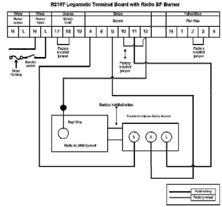
Wiring Diagrams
Heating Contractor:
PRODUCTS MANUFACTURED BYBBT Thermotechnik GmbH35573 Wetzlarwww.buderus.de
BBT North America Corporation50 Wentworth AvenueLondonderry, NH 03053Tel: 603-552-1100 ● Fax: 603-584-1681www.buderus.net
report this adBBT North America Corporation reserves the right to make changes without notice due to continuing engineering and technological advances.
References
[xyz-ips snippet=”download-snippet”]