![]()
Bushnell 201901/201911 GOLF Tour V5 Shift User Guide

Model #: 201901/201911
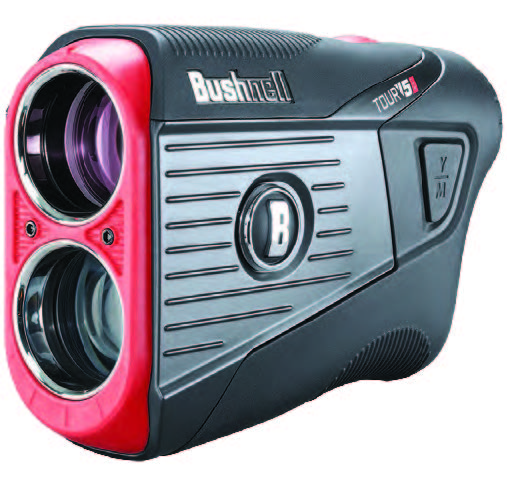
Congratulations on upgrading your game with “BITE” with your purchase of the Bushnell® Tour V5 Laser Rangefinder. The Tour V5 is a precision Laser Range finding optical instrument designed to provide many years of enjoyment. This owner’s guide will help you achieve optimum performance by explaining its features and operation, as well as how to care for your rangefinder. To ensure optimal performance and longevity, please read these instructions before using your Tour V5.
![]() WARNING: As with any laser device, it is not recommended to directly view the emissions for long periods of time with magnified lenses.
WARNING: As with any laser device, it is not recommended to directly view the emissions for long periods of time with magnified lenses.
INTRODUCTION
Your Bushnell® Tour V5 is an advanced premium laser rangefinder comprised of digital technology and turbo processors allowing range readings from 5–1300 yards / 5–1189 meters. The Tour V5 delivers extremely fast acquisition and +/- 1 yard accuracy.
The Tour V5 features PinSeeker™ technology with JOLT, allowing the golfer to easily and quickly “zero” in on the flag without acquiring background targets, and superb optical quality. JOLT has been advanced with the all new “Visual JOLT.” A red ring now flashes as JOLT vibrates to give the golfer even greater feedback and confidence to know you have locked onto the flag.
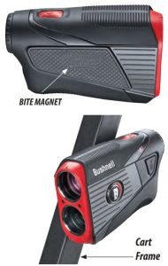
Also new to the Tour V5 is Bushnell’s exclusive BITE magnetic mount that allows you to easily mount the Tour V5 right on the cart bar.
Parts Guide
- BITE Magnet (see inset photo)
- Yards/Meters Switch
- Power/Fire Button
- Eyepiece Diopter Dial
- Battery Compartment
- Slope Switch (Shift model only)

HOW OUR DIGITAL TECHNOLOGY WORKSThe Tour V5 emits invisible, eye safe, infrared energy pulses. The Tour V5 Advanced Digital microprocessor and ASIC chip (Application-Specific Integrated Circuit) results in instantaneous and accurate readings every time. Sophisticated digital technology instantaneously calculates distances by measuring the time it takes for each pulse to travel from the rangefinder, to the target, and back.
RANGING ACCURACYThe ranging accuracy of the Tour V5 is plus or minus one yard / meter under most circumstances. The maximum range of the instrument depends on the reflectivity of the target. The Tour V5 will range to a golf flag at 400 yards / 366 meters, while for highly reflective objects the maximum is 1300 yards / 1189 meters.
Note: You will get both longer and shorter maximum distances depending on the reflective properties of the particular target and the environmental conditions at the time the distance of an object is being measured. The color, surface finish, size and shape of the target all affect reflectivity and range. The greater the reflectivity of the target, the longer the range. A white or silver object is highly reflective, for example, and allows longer ranges than the color black, which is the least reflective color. A shiny or glossy finish provides more range than a dull one. Asmall target is more difficult to range than a larger target. The angle to the target also has an effect. Shooting to a target at a 90 degree angle (where the target surface is perpendicular to the flight path of the emitted energy pulses) provides good range while a steep angle on the other hand, provides limited ranging. In addition, lighting conditions (e.g. the amount of sunlight) will affect the ranging capabilities of the unit. The less light (e.g. overcast skies) the farther the unit’s maximum range will be. Conversely, very sunny days will decrease the unit’s maximum range.
ACTIVATING/REPLACING THE BATTERY
Remove the battery cover by lifting the battery cover tab and then rotating the cover counter clockwise until it is loose. Lift off the cover and set it aside.
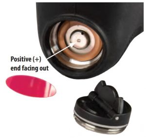
ACTIVATING THE INSTALLED BATTERY: A CR2 battery is pre-installed in your new Tour V5. Before using the rangefinder, remove the battery cover as described above. Remove the red plastic protective disc (see photo, right) from the top of the battery, then replace the battery cover.
REPLACING A LOW BATTERY: Insert a new CR2 3-volt lithium battery into the compartment negative (flat) end first (positive end facing out towards the battery cover), then replace the battery cover. Note: It is recommended that the battery be replaced at least once every 6 months.
BASIC OPERATION
- While looking through the Tour V5, depress the Power/Fire button once to activate the display. If the display icons and numbers are blurry, rotate the eyepiece in either direction until they are in focus (see “Adjusting the Eyepiece” below).
- Placing the aiming circle (center of the display) over a target at least 5 yards away, press and hold the Power/Fire button until the “line of sight” distance is displayed near the bottom of the display (see “Display Indicators” below). Crosshairs surrounding the aiming circle indicate that the laser is being transmitted.
- After a range has been acquired and displayed, you can release the Power/Fire button. The crosshairs surrounding the aiming circle will disappear once the Power/Fire button has been released (i.e. the laser is no longer being transmitted).
- Once activated, the display will remain visible and continue to display the last distance measurement for 10 seconds.You can press the Power/Fire button again at any time to range to a new target. The maximum time the laser is transmitted (active) is 5 seconds. To re-fire, press the button down again.
USING PINSEEKER™ WITH VISUAL JOLT®
Bushnell’s exclusive Pinseeker™ feature allows reliable targeting of the flag without inadvertently getting distances to large background targets (i.e. trees) that have stronger signal strength.When ranging your target, if the laser beam recognized more than one object (for example, the flag and a group of trees behind it), only the distance to the closest object (the flag) will be displayed. The JOLT Technology provides two short bursts of vibration to confirm that the distance displayed is to the flag, and the red ring (Visual JOLT Indicator) around the outer edge of the display is activated, confirming the laser has ranged the correct target via Pinseeker. There may be times when the laser beam only sees one object in its path. In this case, the distance will be displayed, but because more than one object was not acquired, no JOLT indication will be provided.
Tip: While pressing the Power/Fire button, you can move the device slowly from object to object and intentionally force the laser to hit multiple objects to ensure that you are only displaying the closest of the objects recognized by the laser. Once the device has shut off, the unit will always default back to the last mode used.
ADJUSTING THE EYEPIECEThe Tour V5 is equipped with an adjustable Fast Focus eyepiece (+/- 3.5 diopter adjustment) that allows you to focus the displayed data and icons relative to the viewed image from the monocular optics. Simply rotate the eyepiece until the display is in focus.
DISPLAY INDICATORS
Your Tour V5 display incorporates the following indicators (refer to display image at right):

- Aiming Circle (surrounding crosshairs indicate laser transmission)
- Battery Level
- “Play As” Distance* (based on Slope)
- Slope* (% grade)
- Line of Sight Distance
- Visual JOLT Indicator Ring *Shift model only
BATTERY LEVEL INDICATORThe Battery Indicator (2) shows remaining power level:
ACTIVE LASERCrosshairs surrounding the aiming circle indicate that the laser is being transmitted. Once a range has been acquired, you can release the Power/Fire button. The crosshairs surrounding the circle will disappear once the Power/Fire button has been released (i.e. the laser is no longer being transmitted).
SLOPE SWITCH TECHNOLOGY (TOUR V5 SHIFT MODEL# 201911 ONLY)
Slope-Switch Technology lets the golfer easily turn Bushnell’s patented Slope function on and off. This allows the golfer to conveniently utilize Slope to get compensated distances around the course when they want it and have a USGA conforming device that is legal for tournament play when they need it.

When slope is enabled by sliding the Slope Switch on the side of the Tour V5 Shift (model# 201911) to the left so the red Slope indicator is visible (see photo, right), Bushnell’s patented Slope Technology is displayed. The Slope +/- mode will automatically compute an angle compensated range based upon distance and slope determined by the laser rangefinder and built-in inclinometer. This data is then combined with internal algorithmic formulas dealing with average club use and ball trajectories. The angle compensated range provides direction on how to play the shot (i.e. add distance if an incline, subtract distance if a decline). Slide the Slope Switch right, and your Tour V5 now conforms to USGA Rule 14-3, with the slope compensated ranging feature removed.
HOW TO USE SLOPE +/-™ (TOUR V5 SHIFT MODEL# 201911 ONLY)
Move the slope switch to the “Slope On” position. You will see a second row of information appear in the display, confirming that you are now in slope mode. Press the Power/Fire button to obtain distance to the flag or other objects. Once the range is displayed, release the Power/Fire button. Once you have released the Power/Fire button, a grade percentage and compensated range will be displayed beneath the standard distance in the second row of numbers.
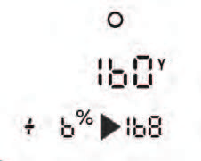
For example, if the true distance is 160 yards, but with a slope of +6 percent, the slope compensated (“play-as”) range is 168 yards. The display would show this (right):
THE ADVANTAGE OF SLOPE +/-™ (TOUR V5 SHIFT)
The distance to the black flag in the drawing (see below) is 160 yards. It is also 160 yards to the red flag, although it is on a slope with a 6% grade (uphill incline). However, if a golfer were to play this hole as 160 yards, the ball (X) would fall short of the hole/flag if slope was not taken into account. Due to the slope, it should be played as a 168 yard shot. This will be displayed as the “play as” distance below the line of sight distance.

SETTING DISTANCE UNITS/JOLT PREVIEW
To select distance units (yards<>meters), press Fire/Power (right) to turn the unit on, then hold the Y/M button until units change in display.
This also activates the JOLT indicators (vibration and visual ring in display), allowing you to preview/demo the effect of JOLT Technology without requiring you to fire the laser at a target.

BITE MAGNETIC MOUNT
The Tour V5 features a powerful BITE magnet incorporated into the right side of its housing, which allows the device to be securely attached to a golf cart bar or frame.
![]() WARNING: Bite feature included with device contains a Neodymium magnet. Magnets could affect the functioning of pacemakers and implanted heart defibrillators. If you use these devices, keep sufficient distance from magnet. Warn others who wear these devices from getting too close to magnets.
WARNING: Bite feature included with device contains a Neodymium magnet. Magnets could affect the functioning of pacemakers and implanted heart defibrillators. If you use these devices, keep sufficient distance from magnet. Warn others who wear these devices from getting too close to magnets.
- Magnet may lose part of its adhesive force permanently if exposed to temperatures above 175o F (80o C).
- Magnets produce far-reaching, strong magnetic field. They could damage TVs and laptops, computer hard drives, credit and ATM cards, data storage media, mechanical watches, hearing aids and speakers. Keep unit away from devices and objects that could be damaged by strong magnetic fields.
- Magnets have strong magnetic fields which can pinch skin and fingers. Use caution when attaching the unit to a metal bar.
CLEANING AND GENERAL CARE
The lenses of your Bushnell Tour V5 laser rangefinder are fully multi-coated for highest light transmission. As with any multicoated optics, special care must be taken in cleaning the lenses. Follow these tips for proper lens cleaning:
- Blow away any dust or debris on the lens (or use a soft lens brush).
- To remove dirt or finger prints, clean with the supplied micro-fiber cloth rubbing in a circular motion. Use of a coarse cloth or unnecessary rubbing may scratch the lens surface and eventually cause permanent damage. The included washable microfiber cleaning cloth is ideal for the routine cleaning of your optics. Simply breathe lightly on the lens to provide a slight amount of moisture, then gently rub the lens with the microfiber cloth.
- For a more thorough cleaning, photographic lens tissue and photographic-type lens cleaning fluid or isopropyl alcohol may be used. Always apply the fluid to the cleaning cloth – never directly on the lens.
- The rangefinder is water resistant, but should not be exposed to heavy rain or other direct streams of water, and will not withstand submersion in water or other liquids.
![]() CAUTION: Use caution to avoid direct sunlight into the eyepiece to prevent damage to the display/internal components.
CAUTION: Use caution to avoid direct sunlight into the eyepiece to prevent damage to the display/internal components.
When using the BITE magnet to attach the device to a cart bar or frame, tilt the device so the eyepiece is aimed towards the ground, not pointed upwards towards the sun. When you are not using the device, please store it in the case for additional protection.
TROUBLESHOOTING
Never disassemble your laser rangefinder. Irreparable damage can result from unauthorized service attempts, which also void the warranty.
If unit does not turn on, display does not illuminate:
- Depress Power/Fire button.
- Check and if necessary, replace battery. If unit does not respond to button presses, replace the battery with a good quality CR2 3-volt Lithium battery.
If unit powers down (display goes blank when attempting to power the laser):
- The battery is either weak or low quality. Replace the battery with a new 3 -volt lithium battery (CR2).
If target range cannot be obtained:
- Make sure the display is illuminated.
- Make sure that the Power/Fire button is being depressed.
- Make sure that nothing, such as your hand or finger, is blocking the objective lenses (lenses closest to the target) that emit and receive the laser pulses.
- Make sure unit is held steady while depressing Power/Fire button.
NOTE: The last range reading does not need to be cleared before ranging another target. Simply aim at the new target using the display reticle, depress the Power/Fire button and hold until new range reading is displayed.
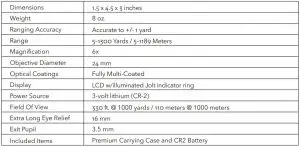
Technical Specifications
![]() WARNING: This product uses a Lithium based battery. Lithium batteries can overheat and cause damage if physically abused. Do not use batteries that are damaged or show signs of physical wear.
WARNING: This product uses a Lithium based battery. Lithium batteries can overheat and cause damage if physically abused. Do not use batteries that are damaged or show signs of physical wear.
FCC StatementThis device complies with part 15 of the FCC Rules. Operation is subject to the following two conditions: (1) This device may not cause harmful interference, and (2) this device must accept any interference received, including interference that may cause undesired operation.
This equipment has been tested and found to comply with the limits for a Class B digital device, pursuant to Part 15 of the FCC Rules. These limits are designed to provide reasonable protection against harmful interference in a residential installation.
This equipment generates, uses and can radiate radio frequency energy and, if not installed and used in accordance with the instructions, may cause harmful interference to radio communications. However, there is no guarantee that interference will not occur in a particular installation.
If this equipment does cause harmful interference to radio or television reception, which can be determined by turning the equipment off and on, the user is encouraged to try to correct the interference by one or more of the following measures:
- Reorient or relocate the receiving antenna.
- Increase the separation between the equipment and receiver.
- Connect the equipment into an outlet on a circuit different from that to which the receiver is connected.
- Consult the dealer or an experienced radio/TV technician for help.
Service Notes:
- The consumer may remove the battery door to replace the battery.
- This product contains no user serviceable controls.
- This product must not be opened or modified by the consumer.
- This product must be returned to the manufacturer for service.
Contact : Bushnell Holdings, Inc.9200 Cody, Overland Park KS 66214
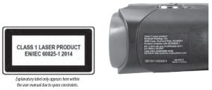

FDA SAFETY
Complies with 21CFR1040.10 and 1040.11 except for conformance with IEC60825-1 Ed.3., as described in Laser Notice 56, dated May 8, 2019
Caution- use of controls or adjustments or performance of procedures other than those specified herein may result in hazardous radiation exposure.
Industry Canada Statement :This device complies with ISED’s licence-exempt RSSs. Operation is subject to the following two conditions: (1) This device may not cause harmful interference, and (2) this device mustaccept any interference received, including interference that may cause undesired operation.
Radiation Exposure StatementThis device complies with the Industry Canada portable RF exposure limit set forth for an uncontrolled environment and is safe for the intended operation as described in this manual. Further RF exposure reduction can be achieved if the product can be kept as far as possible from the user’s body or if the device is set to a lower output power if such function is available.
http://patents.vistaoutdoor.comDisposal of Electric and Electronic Equipment(Applicable in the EU and other European countries with separate collection systems)
![]() This equipment contains electric and/or electronic parts and must therefore not be disposed of as normal household waste. Instead, it should be disposed at the respective collection points for recycling provided by the communities. For you, this is free of charge.
This equipment contains electric and/or electronic parts and must therefore not be disposed of as normal household waste. Instead, it should be disposed at the respective collection points for recycling provided by the communities. For you, this is free of charge.
If the equipment contains exchangeable (rechargeable) batteries, these too must be removed before and, if necessary, in turn be disposed of according to the relevant regulations (see also the respective comments in this unit’s instructions).
Further information about the subject is available at your community administration, your local waste collection company, or in the store where you purchased this equipment.
TWO-YEAR LIMITED WARRANTY
Your Bushnell® golf laser rangefinder is warranted to be free of defects in materials and workmanship for two years after the date of purchase. In the event of a defect under this warranty, we will, at our option, repair or replace the product, provided that you return theproduct postage prepaid. This warranty does not cover damages caused by misuse, improper handling, installation, or maintenance provided by someone other than a Bushnell® Authorized Service Department.
Any return made under this warranty must be accompanied by the items listed below:
- A check/money order in the amount of $10.00 to cover the cost of postage and handling
- Name, address and daytime phone # for product return.
- An explanation of the defect.
- Copy of your dated proof of purchase.
Do not send in accessories (batteries, case, strap, etc.), only the product for repair.Product should be well packed in a sturdy outside shipping carton to prevent damage in transit, and shipped to the address listed below:
IN U.S.A. Send To:Bushnell® Outdoor ProductsAttn.: Repairs9200 CodyOverland Park, Kansas 66214
IN CANADA Send To:Bushnell® Outdoor ProductsAttn.: Repairs140 Great Gulf Drive, Unit BVaughan, Ontario L4K 5W1
For products purchased outside the United States or Canada please contact your local dealer for applicable warranty information.
This warranty gives you specific legal rights.You may have other rights which vary from country to country.©2020 Bushnell® Outdoor Products
![]()
©2020 Bushnell Outdoor ProductsBushnell,™, ®, denote trademarks of Bushnell Outdoor Productswww.bushnell.com9200 Cody, Overland Park, KS 66214
References
[xyz-ips snippet=”download-snippet”]