WallHound Cell Phone Deterrent / DetectorUser Manual Version 1.4
Introduction
WallHound ships in the default `cell phone detection mode. If you would like to enable Bluetooth, WiFi, and cellular phone detection in any combination, you can do this in the Windows PC utility supplied on USB Stick. See the end of this manual for PC software setup instructions. Below are a few quick tips to help you get your unit configured:
Left Side Controls: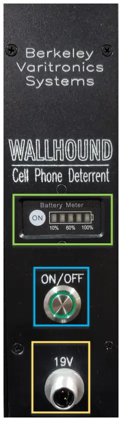 |
Right Side Controls: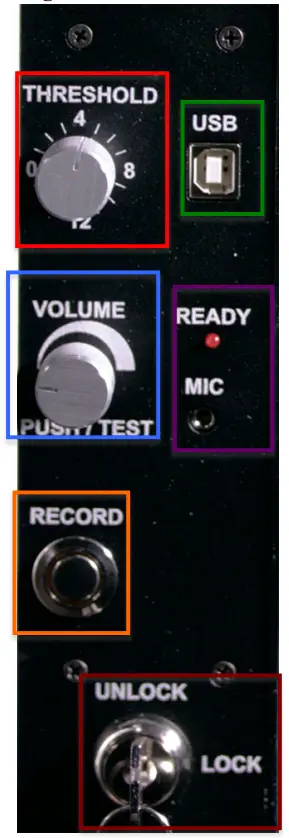 |
Unboxing
WallHound ships in a box with custom inserts and packaging materials to ensure safe delivery. Be sure to retain all shipping boxes that your WallHound unit and accessories arrived in should you need to send your unit back to the factory for updates or repair.
 Hardware Controls
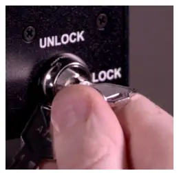 |
Locking and Unlocking Your WallHound includes a provision to securely lock all settings to prevent tampering with an included key. Settings such as volume, threshold, power, and recording custom audio messages may not be changed while the WallHound is in the “Locked” position. All settings of switches and rotary controls can only be performed in the “Unlock” position of the key switch. | |
When adjustments are complete, the key switch should be placed into the locked position and the key removed and stowed. This action will write and save the setup into the WallHound’s local memory.
Adjusting Alert Volume
Volume control is infinitely adjustable clockwise to increase the volume of the audio and counter-clockwise to decrease the volume. The adjustment must be performed while the WallHound is in the “Test” mode which is selected while the red “Ready” LED is lit and the volume control is pushed in momentarily. In this mode, the display will blink approximately twice per second (to indicate it is in “Test” mode) and allow the volume knob to be rotated to a suitable setting. Adjustment should end with the red “Ready” LED light being lit. When you finish making volume adjustments, depress the volume knob once again to exit the “Test” mode and register this setting in the WallHound’s memory.
Adjusting Threshold Sensitivity
The threshold value can be adjusted from “0” (most sensitive) to “15” (least sensitive) only when the key switch is in the “Unlock” position. Due to the nature of RF cellular detection, these numbers do not correspond to any distance or fixed value but rather an algorithm used by WallHound to ignore “noisy” RF environments and other forms of interference. Some RF interference such as elevator shafts, large windows, and reinforced steel construction is integral to the structure or facility. While the facility cannot be altered easily, the WallHound can be relocated to areas that experience less interference or possibly false triggers. Before permanently mounting to a wall, try positioning WallHound in different areas of the building or perimeter and note the optimum threshold setting at each location.
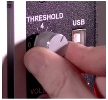
Once the Threshold is adjusted, the key switch should be moved to the “Lock” position to register the setting in the WallHound’s memory.
Recording Custom Audio Alerts
Recording of a custom message is accomplished by first unlocking the key switch. Plugin the included microphone to the corresponding 3.5mm audio input on the side. Depress and hold the “Record” button while speaking into the microphone a few inches away from your mouth. Release the “Record” button when you have finished your desired statement and turn the key switch to “Lock”. This will register and save your message in the WallHound’s memory.
Battery Power
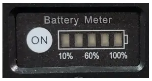
The WallHound cell phone deterrent includes an internal, rechargeable battery system (Powersonic Model PS-1220 Rechargeable Sealed Lead Acid Battery 12 Volt DC 2.5 Amp-Hr.) which will power the unit for about an hour. This makes uninterrupted temporary moving and setup of the unit convenient for security staff and also provides backup power in the advent of power loss.The battery meter is located on the bottom left side of the unit. When you press the `ON’ button on the battery meter you will get status indicated by GREEN LED’s indicating the percentage of charge on the internal battery. The battery gauge is measured in (5) increments consisting of 20% for each GREEN LED increment. (ie. 5 GREEN LED’s indicate a battery that is 100% charged) Simply plug in the AC power cord at any time to trickle charge the internal battery. Fully trickle charging the battery from completely empty takes 12 hours and is recommended to be done overnight or when the unit is not in use. WallHound is not designed to run off its internal battery all the time. BVS advises customers to normally operate WallHound continuously using AC power.
 An AC power failure or removal of the AC power cord will automatically switch the WallHound into the internal battery mode. Conversely, connection to AC power will automatically begin charging the internal battery. The unit will continue to run using this battery until it is depleted. If the battery “Monitor” switch on the bottom of the unit is set to “on”, a beeping sound will be heard just before the internal battery is depleted reminding everyone that the battery must now be recharged.
WallHound Bottom Side Controls
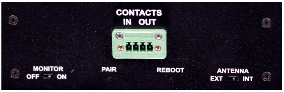
Selecting Antennas
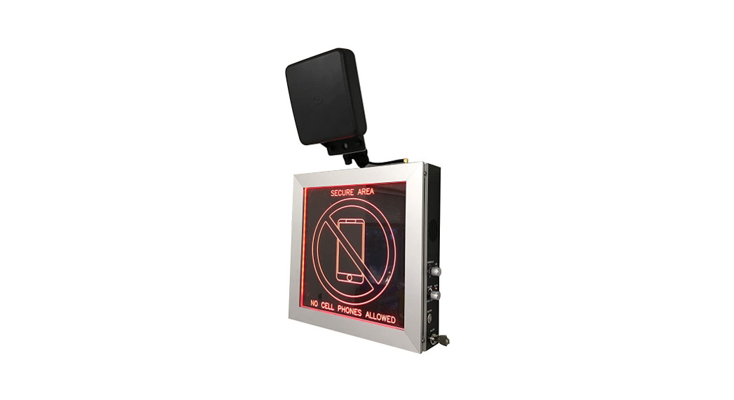
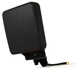
WallHound includes an internal omnidirectional antenna that can detect active cell phone use up to 100 feet away in any direction. WallHound also supports an optional DF (Direction Finding) Antenna system for users who wish to target specific corridors, hallways, or entrances. The DF antenna has a narrower field of detection than WallHound’s built-in internal antenna. Use of the DF antenna would also be advised for false triggers originating from the side or behind the mounted unit.Antenna selection is accomplished by setting the key switch to “Unlock” and setting the Antenna switch on the bottom of the unit to “Ext” for external (connector is on top of WallHound) or “Int” for internal antenna hidden inside the WallHound case. The antenna switch is recessed but easily switched using a small screwdriver, paper clip, or toothpick. Set the key switch to “Lock” to register this setting in the WallHound’s memory. Contact Switch For Remote Triggering SPST (Single Pole Single Throw) normally open contact switch closure port is available on the bottom of the WallHound. This analog switch (60vdc/100ma max) is synchronized to the alert message and red backlit display so that alerts may be triggered by staff remotely.
Optional Accessories
WallHound works with a variety of optional accessories that enhance the performance and versatility of the product. Ask your BVS sales representative about these accessories or visit www.bvsystems.com to learn more.
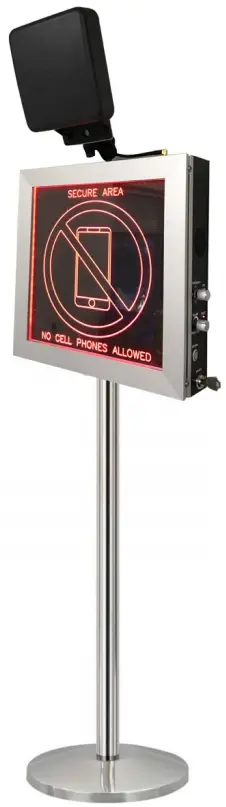
WallHound stanchion mount includes a weighted base and stainless steel pole allowing the unit to be moved and placed anywhere instantly.
 WallHound direction-finding antenna includes all the cables and mounting gear allowing users to create more focused RF detection zones down narrow corridors or hallways without false triggering from active RF sources in other areas.
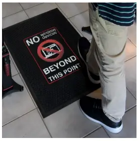
 Rugged entryway mats are perfect for reminding staff and visitors that wireless devices are prohibited beyond a certain point in the facility.
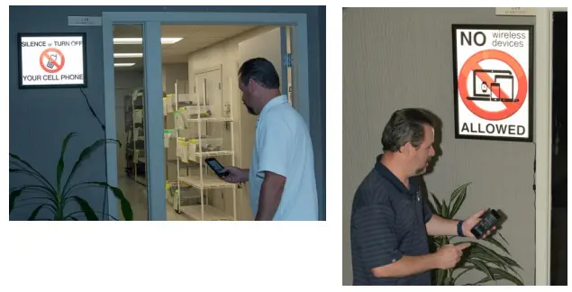
 These custom LED backlit signs to provide a clear message to all staff and visitors that wireless devices are prohibited.
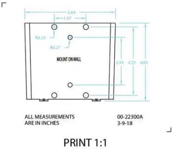
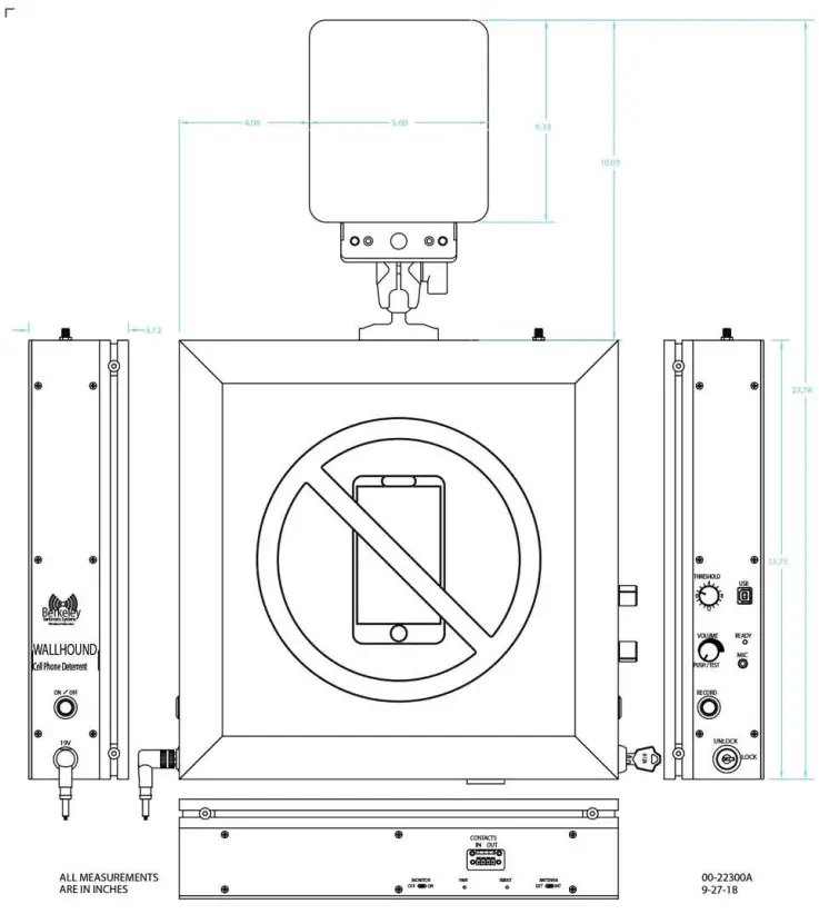
WallHound Mechanical Drawing
Three examples of remote alarms triggered from a dry contact in your BVS product (Similar outputs are provided in all wall-mounted BVS products)
report this ad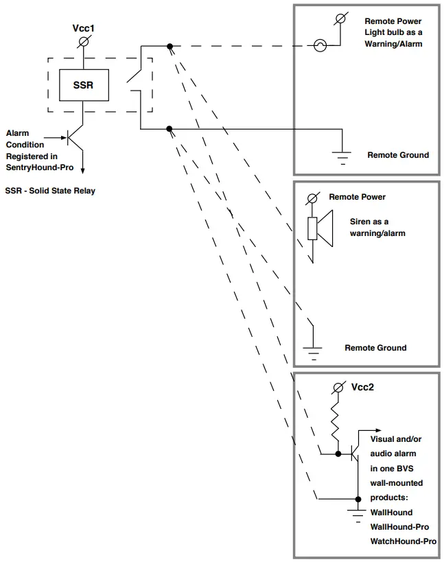
Using the WallHound Configurator Quick Start Software
- Install the WallHound Configurator software on the supplied USB stick. Please check if the Windows PC/Laptop/Notebook has .Net Framework 4.0 installed. If not, install .Net Framework 4.0 supplied on the USB stick first. Then install the WallHound Configurator Software.To install the drivers for the WallHound hardware, plug the WallHound into the Windows PC/Laptop with the USB cable and open the device manager and open the WallHound icon Properties and browse to the driver’s folder on the USB stick and click Next to install the drivers. If a dialog with Install Anyway comes up, click “Install Anyway”. This should take a few moments. Do not stop the installation. Pull the USB cable out.
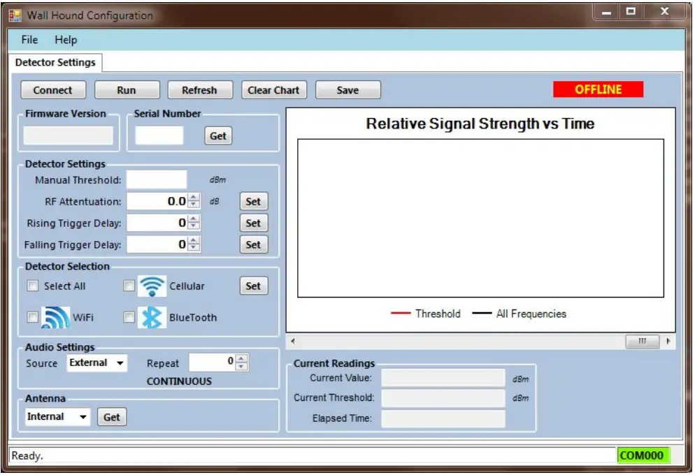
- After installing the software Unlock the Wall Hound unit with the key and start the software by clicking the WallHound Configurator Icon on the desktop.You will see the following screen:
- To connect to the WallHound, plug in the USB cable into the WallHound unit. Windows will signal recognition of the device with a USB plug-in sound.
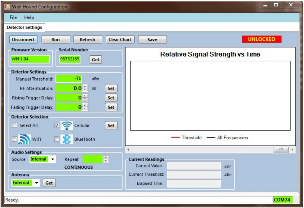
- Click the Connect button and you will see the following screen:
- Notice various fields have been populated and the COM port is displayed on the status line at the bottom of the window.
- Select the detector type desired by selecting Cellular, WiFi, and Bluetooth. Notice that Cellular is selected. Press the Set button near the Detector Selection checkboxes when the selection is complete to apply the settings.
- To set the detection Threshold, click the Run button on top of the Configurator window and you will see the strip chart running and look something like the following:
- Adjust the threshold with the knob on the side of the WallHound unit until the red threshold line is at a level suited to the particular location where the specific signal level exceeding the threshold will set off the alarm.
- When done, click the Stop button and then click the Disconnect button.
- Before locking the WallHound unit, exit the application by selecting File/Exit in the menu or clicking the “x” in the upper right-hand corner of the window.
- Unplug the USB cable.
- Lock the WallHound unit and don’t forget to pull the key out.
Thank you for your purchase, we look forward to supporting you and your team.
Customer SupportBerkeley Varitronics Systems, Inc.Liberty Corporate Park255 Liberty StreetMetuchen, NJ 088408:00 AM to 6:00 PM ESTToll-Free: 888-737-4287Phone: 732-548-3737Fax: 732-548-340424/7email: [email protected]www.bvsystems.com
References
[xyz-ips snippet=”download-snippet”]