BWT TFPKIT Taste Fresh Protection Drinking Water System Instruction Manual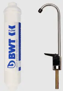
Parts Included
- Filter head with built-in mounting bracket, and integral push-fits
- 1000R filter cartridge
- Screws for mounting bracket
- Saddle tapping valve with tube attached
- Drinking water tap
- 6.35 mm (1/4”) plastic tubing
Tools required
- Phillips Screwdriver
- Towel
- Drill
- Tape Measure
- File or Sandpaper
- Pencil
- 3.2 mm (1/8”) Drill Bit
- Adjustable Wrench
Optional Materials
- 6.3mm & 12.7 mm (1/4” & 1/2”) Drill Bit
- Cone-shaped grinding wheel
Precautions
- WARNING: Do not use with water that is microbiologically unsafe or of unknown quality without adequate disinfection before or after the system. Systems certified for cyst reduction may be used on disinfected waters that may contain filterable cysts.
- CAUTION: This filter must be protected from freezing, which can cause cracking of the filter and water leakage.
- CAUTION: Because of the product’s limited service life and to prevent costly repairs or possible water damage, we strongly recommend that the head of the filter be replaced every ten years. If the head of your filter has been in use for longer than this period, it should be replaced immediately. Date the top of any new head to indicate the next recommended replacement date.
- CAUTION: Turn off water supply to head without cartridge if it must be left unattended for an extended period of time.
- For cold water use only.
- Make certain that installation complies with all local bylaws and regulations.
- The contaminants or other substances removed or reduced by the selected cartridge are not necessarily in your water. Ask your local water supplier for a copy of their water analysis.
- After prolonged periods of non-use (such as during a holiday) it is recommended that the system be flushed thoroughly. Let water run for 2-3 minutes before using.
- The filter cartridge used with this system has a limited service life. Changes in taste, odour colour; and/or flow of the water being filtered indicate that the cartridge should be replaced.
Installations
- For standard installation on 15 mm copper, steel, brass or PVC cold water pipe.
- Please read all instructions and precautions before installing and using your under-sink drinking water system.
- Numbered diagrams correspond with numbered steps.
Selecting the Tap Location
NOTE: The drinking water tap should be positioned with function, convenience and appearance in mind. An adequate flat area is required to allow tap base to rest securely. The tap fits through a 12 mm hole.
CAUTION: Do not attempt to drill through an all-porcelain sink. If you have an all-porcelain sink, drill through counter top next to sink. The following instructions apply to porcelain-coated cast iron and stainless steel sinks only. Consult a professional plumber about installation on an all-porcelain sink. (Continued overleaf)
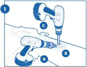
- (A) Line bottom of sink with newspaper to prevent metal shavings, parts, or tools from falling down drain and damaging sink disposal unit if fitted.
- (B) If sink is porcelain-coated, place masking tape over are to be drilled to prevent excess chipping of enamel. Use a cone-shaped grinding wheel to grind away a 3/4-inch diameter circle of porcelain before drilling.WARNING: Wear safety glasses to prevent eye injury.
- (C) Mark hole with center punch. Use a 6mm drill bit for a pilot hole, then using a 12mm diameter bit, drill a hole completely through the sink or worktop. Smooth rough edges with a file.
Mounting the Tap
- The tap should be positioned on a work surface adjacent to a sink where the spout can properly discharge water into the basin.
- Using a pencil, mark the work surface to indicate the centre of the tap.
- Drill a 1/2” hole where marked on the work surface.
- Insert the black rubber washer into the base of the tap.
- Insert the threaded section of the tap body into the 1/2” hole.
- Assemble the washers and lock nut on the threaded section as over.
- Tighten the lock nut to prevent the tap moving. Do not over tighten.
- Ensure compression nut, ferrule and tub insert are positioned on the blue flexible tubes shown over.
- Insert the open end of the blue flexible tube assembly into the base of the threaded section of the tap.
- Tighten the compression nut to ensure a watertight seal.Do not over tighten.

Installing the Saddle Valve
Before carrying out any installation TURN OFF THE WATER SUPPLY AT THE MAIN STOP COCK.
- Place the saddle clamp on to the cold mains supply pipe to the kitchen sink. Make sure that the saddle A is in place as shown in the diagram.
- Tighten the locking screw C to clamp the pipe securely.
- Turn the piercing screw B clockwise and fully home to puncture the pipe.
- Leave in this position until final assembly (see section 7)
Mounting the Filter System
- Select location under sink where filter is to be mounted.NOTE: Allow 50 mm clearance below housing or 280mm below filter head to enable filter cartridge changes.CAUTION: Filter head should be mounted on stud or firm surface. Themounting bracket will support the weight of the filter and prevent the strain on the cold water line.
- Filter head should be mounted in vertical position, use mounting bracket as a template to mark screw locations. Mount filter head in marked location using screws.
Connecting the Saddle Valve & Tap Tube to the Filter Head
The cartridge head tube fitting system is a push-fi t system where the tube securing mechanism is integrated into the cartridge head itself.
First make sure the tube ends are clean. Just push the tube end squarely into the joint housing in the cartridge head, until it hits the shoulder (approximately 10-15 mm) referring to the arrows on top of the housing to indicate flow direction and that pipes are connected appropriately. (See image opposite) Once the tube is in place, to confirm that the joint is secure, tug gently backwards on the tube.
The tube should now be secure.
If for any reason you need to remove one of the tubes, press the blue compression ring in the corresponding cartridge head housing inwards. This should free the tube and allow easy removal.
Installing the Cartridge
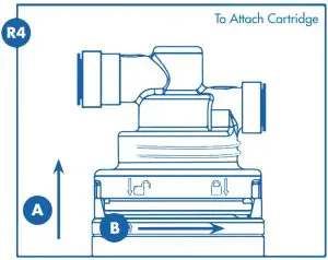
Hold cartridge from the bottom when installing or changing the cartridge.Use caution not to scrape knuckles on bracket when locking the cartridge into place. Line up the arrow on the cartridge with unlocked padlock on head.Insert cartridge and turn arrow to locked padlock. (See Diagram R4)
Putting the Filter into Operation
- Open the quarter turn tap fully to allow for continuous fl ow, then slowly turn the piercing screw B anti-clockwise allowing water to enter the filter slowly and displace trapped air and loose particles.
- When the water runs clear, turn the piercing screw B anti-clockwise until fully open and the water flows at maximum rate, (1.9 L/min).
- Allow water to fl ow through the system for around 15 minutes when first installed or when left unused for a prolonged period of time.
- Always flush for 10 seconds prior to use.
- Check for leaks before leaving installation. If it leaks, see Troubleshooting.
Filter Cartridge Replacement
NOTE: It is recommended that the cartridge be replaced every six months, orwhen you notice a change in taste, odour, or fl ow of the water being fi ltered.
- Turn off the water supply to the fi lter and dispense water from drinking water tap until water fl ow stops to relieve pressure.
- Place towel under the system to catch any water drips.
- (a) Turn arrow from locked to unlocked position.(b) Remove cartridge.
- (a) Line up arrow with unlocked position on head and insert cartridge.(b) Turn to locked position.
- Turn on water and check for leaks. If it leaks, see Troubleshooting.
- Flush water through drinking water tap for 5 minutes to remove carbon fines. Check for leaks before leaving installation. If it leaks, see Troubleshooting.
Troubleshooting
Leaks:
Between head and cartridge
- Turn off the water supply to the fi lter and dispense water from drinking water tap until water and airfl ow stops.
- Remove cartridge and inspect o-rings to make sure that they are in place and clean.
- Install cartridge and turn on water supply. If leaks persist, contact Technical Support on 01494 838100
On other connections
Call Technical Support on 01494 838100
| U.S EPA MCL* | Avg. Influent Concentration | Avg.(Max) Effluent Concentration | Avg.(Min) Reduction | |
| Standard 42 | ||||
| Chlorine-Class I | -** | 2.1 ppm | 0.02 ppm | 99% |
| Particulates (0.5 to<5 µm) -Class I | -** | 7,108,826#/ml | 15,896 #/ml | 99.8% |
| Standard 53 | ||||
| Cysts † | 99.95% Reduction | 130,750 #/ml | 0 #/ml(0 #/ml) | 99.99%(99.99%) |
| Turbidity | 0.5 NTU* | 37.4 NTU | 0.08 NTU (0.08 NTU) | 999.96%99.95%) |
| Lead (6.5 pH) | 0.010 ppb‡ | 0.15 mg/L | 0.001 mg/L (0.001 mg/L) | 99.3%(99.3%) |
| Lead (8.5 pH) | 0.010 ppb‡ | 0.15 mg/L | 0.002 mg/L (0.003 mg/L) | 98.6%(98%) |
| Atrazine | 0.003 mg/L | 0.0088 mg/L | 0.0002 mg/L(0.0002 mg/L) | 97.7%(97.7%) |
| Lindane | 0.0002 mg/L | 0.002 mg/L | 0.00005 mg/L(0.00005 mg/L) | (97.5%)(97.5%) |
Performance Data
Model: Taste Fresh Protection
Important Notice: Read this performance data and compare the capabilities of this system with your actual water treatment needs.
Test Conditions:
- Flow Rate = 0.5 gpm
- Inlet Pressure = 60 psi (4.1 bar)
- pH = 7.5 ± 1
- Temperature = 68°F ± 5°F (20°C ± 2.5°C)
Operating Requirements
- Pressure = 30 – 72psi (2.1 – 5 bar)
- Temperature = 40° – 100°F (4.4o-37.7°C)
- Turbidity = 5 NTU Max
Do not use with water that is microbiologically unsafe or unknown quality without adequate disinfection before or after the system. Systems certified for cyst reduction may be used on disinfected waters that may contain filterable cysts.
Flow Rate: 1.89 Lpm Capacity: 1892L or 6 Months
- US EPA Maximum Contaminant Level
- No maximum contaminant level
- NSF test requirement of at least 50,000 3-4 micron particles per millilitre.
The 3-4 micron size particle is a surrogate particle for Cryptosporidium and Giardia cysts.
- US EPA Action Level for lead
NOTE: Substances reduced are not necessarily in your water. Filter must be maintained according to manufacturer’s instructions, including replacement of filter cartridges.
Guarantee
This product is guaranteed for the period of one year from the date of purchase against any manufacturing fault. The guarantee is only valid if the product has been installed and used in accordance with the manufacturers instructions and has not been dismantled or interfered with in any way. Damage caused to the product or by the product as a result of failure to use the product in accordance with the manufacturer’s instructions is not covered by this guarantee. Under this guarantee we undertake at our discretion to repair or replace free of charge the product or any part thereof that is found to be faulty. Costs associated with the fi tting of a replacement product or part or the removal of the product are not covered by this guarantee.Loss or damage caused by the product (including consequential loss) is not covered by this guarantee. This guarantee does not affect your statutory rights.
Customer Help Line
Tell: 01494 838100Monday to Friday 08.30 – 17.00BWT UK Limited, BWT House,Coronation Road, High Wycombe, Buckinghamshire, HP12 3SUTel: 01494 838100Fax: 01494 838101Email: [email protected]
 report this ad
All trademarks are protected under European law and must not be reproduced by third parties without express permission of BWT UK Limited in writing. As part of BWT’s policy of constant product development, BWT reserves the right to alter product specifications without prior notice.
[xyz-ips snippet=”download-snippet”]