![]()
The Hot One Garage HeaterOwner’s Guide
Benefits You Can Depend On
- Ultra-portable with six-foot cord and polarized plug (proper receptacle required)
- HI/LOW switch provides two options for heat output
- Use the fan by itself for air-only circulation
- Built-in adjustable thermostat with ‘off’ position
- Peace of mind with high-temperature safety shut off feature
- Includes bracket for wall mount, ceiling mount, or floor stand used
- Your Cadet heater has been thoroughly tested and is guaranteed a limited 5-year warranty
|
The Hot One Specification Table |
||||
| Volts | Model withthermostat | Wattshigh/low | Ampshigh/low | Plug Type |
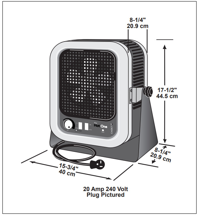
| 240 | RCP502S | 5000/3333 | 20.8/13.9 | 30 Amp |
| RCP402S | 4000/2667 | 16.7/11.1 | 20 Amp |
The Hot One is recommended for elevations under 7500 feet.
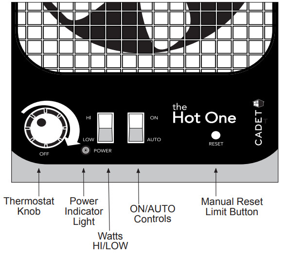
The Hot One Heater Controls:
TOOLS REQUIRED OR YOU MAY NEED:
IMPORTANT INSTRUCTIONS
When using electrical appliances, basic precautions should always be followed to reduce the risk of fire, electric shock, and injury to persons, including the following:
- Read all instructions before using this heater.
- This heater is hot when in use. To avoid burns, do not let bare skin touch hot surfaces. If provided, use handles when moving this heater. Keep combustible materials, such as furniture, pillows, bedding, papers, clothes, and curtains at least 3 feet (.9 m) from the front of the heater and keep them away from the sides and rear.
- Extreme caution is necessary when any heater is used by or near children or invalids and whenever the heater is left operating and unattended.
- Always unplug the heater when not in use.
- Do not operate any heater with a damaged cord or plug, or after the heater malfunctions, has been dropped or damaged in any manner. Return heater to authorized service facility for examination, electrical or mechanical adjustment, or repair.
- Do not use outdoors.
- This heater is not intended for use in bathrooms, laundry areas, and similar indoor locations. Never locate a heater where it may fall into a bathtub or other water container.
- Do not run cord under carpeting. Do not cover the cord with throw rugs, runners, or similar coverings. Arrange cord away from traffic area and where it will not be tripped over.
- To disconnect the heater, turn controls off, then remove the plug from the receptacle.
- Connect to properly grounded receptacles only.
- Do not insert or allow foreign objects to enter any ventilation or exhaust opening as this may cause an electric shock or fire, or damage the heater.
- To prevent a possible fire, do not block air intakes or exhaust in any manner. Do not use it on soft surfaces, like a bed, where openings may become blocked.
- A heater has hot and arcing or sparking parts inside. Do not use it in areas where gasoline, paint, or flammable vapors or liquids are used or stored.
- Use this heater only as described in this manual. Any other use not recommended by the manufacturer may cause fire, electrical shock, or injury to persons.
- Always plug the heater directly into a wall receptacle. Never use an extension cord or relocatable power tap (receptacle/power strip).
- CAUTION: Do not operate without stand attached.
- Save these instructions.
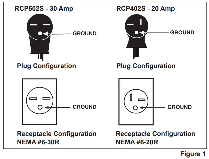
Grounding Plug and Receptacle Requirements
This heater is for use with 240 volts. The cord has a 20 amp or 30 amp plug as shown in Figure 1. No adapter is available for these blade configurations, and none should be used. The Hot One requires a 240 volt grounded receptacle. When properly installed, it provides a ground connection through the cord to the heater to protect the operator from electric shock. Do not use an extension cord, power strip, or any kind of adapter.
 |
 |
INSTALLATION INSTRUCTIONS
- WARNING: Risk of fire. Do not use it as a residential or household heater.
- Do not use outdoors.
- This heater is not intended for use in bathrooms, laundry areas, and similar indoor locations.
- CAUTION: Do not operate without stand attached.
- The heater must be kept clear of all obstructions: 3-foot minimum clearance from the front, 6-inch minimum clearance from back and top, and 12-inch minimum clearance from sides. See Figure 2.
- Always plug the heater directly into a 240-volt wall receptacle. Never use an extension cord.
The Hot One may sit on a floor surface or be mounted to the wall, or on the ceiling, using the universal stand provided. If mounted on the wall, maintain 6 inch minimum clearance from the top of the unit to the ceiling (See Figure 2). Recommended for elevations under 7500 feet.
STEP 1 Heater Inspection
Thoroughly inspect your heater for any shipping or handling damage and remove any paper or packaging material around the heater.
STEP 2 Mounting
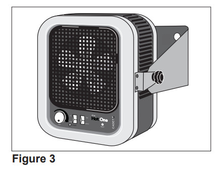
Wall Mount
- Remove the stand from the heater by loosening knobs on each side.
- Place stand in desired position on the wall (See Figure 3). Note: A 240-volt receptacle must be within six feet of the heater.

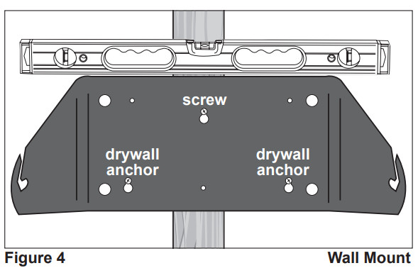
- Using a level across the top of the stand, mark the three keyhole locations indicated (See Figure 4). IMPORTANT: the top, center keyhole must be screwed into a wall stud.
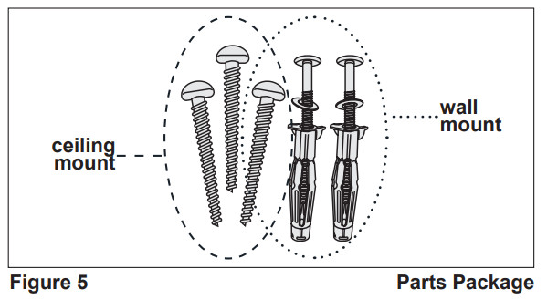
- Insert one of the 2-inch screws provided into the top, center keyhole position, leaving enough of the screw sticking out to attach the stand later (See Figure 6).
- Using an inch drill bit, drill holes through the drywall in each of the two bottom keyhole positions. Insert drywall anchors (provided) in each hole.
- Insert the drywall anchor screws until completely screwed in. Then back each anchor screws out about ½ inch. Place the stand on the three exposed screws and tighten all three screws.
- Place heater on standing and tightening knobs.
- Proceed to OPERATING INSTRUCTIONS.
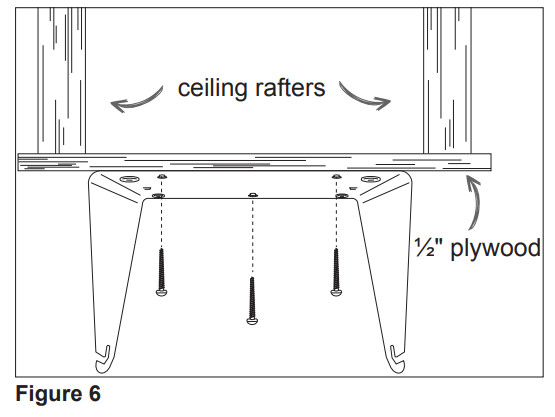
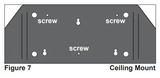
Ceiling Mount
- Securely fasten a piece of plywood (not provided) across two of your ceiling rafters that is a minimum of ½ inch thick, 8 inches wide, and long enough to span the distance across the two rafters (See Figure 6). Note: A 240-volt receptacle must be within six feet of the heater.
- Remove the stand from the heater by loosening knobs on each side.
- Attach the stand to the plywood with the three 2 inch screws provided through the three small holes indicated (See Figures 5, 6, and 7).
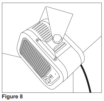
- Place heater on standing and tightening knobs. Tilt top of heater down approximately 30 to 45 degrees toward your work area (See Figure 8).
- Proceed to OPERATING INSTRUCTIONS.
OPERATING INSTRUCTIONS
- The heater must be properly installed before it is used. Be sure the plug fits tightly into the receptacle. The red light indicates the unit is plugged in.
- Do not operate without the stand attached.
- Do not use a breaker panel or wall thermostat to control the heater.
- Always unplug the heater when not in use.
- Clean the heater at least every six months or as required. See “MAINTAINING YOUR HEATER”.
- CAUTION: Risk of electrical shock. Do not open. No user-serviceable parts inside. Any other service not detailed in this owner’s guide should be performed by an authorized service representative.
How to Operate Your HeaterSelect the “LOW” wattage setting. If your desired temperature is not reached, select the “HI” setting. NOTE: The temperature of the air coming from the front of the heater will be approximately 40°F warmer than the room temperature in the “HI” setting. In extremely cold environments, air from the heater may not feel hot. As the heater continues to operate, the heater air and surrounding air temperature will continue to increase.
| Fan cycling with heat | Fan running continuously with intermittent heat | Fan running continuously with no heat |
| 1. Press the ON/AUTO switch to the “AUTO” position and turn the thermostat knob fully clockwise.2. When the room reaches your comfort level, turn the thermostat knob counterclockwise until the heater turns off. The heat and the fan will automatically cycle around this preset temperature.3. To reduce the room temperature, turn the knobcounterclockwise. To increase the room temperature, turn the knob clockwise. | Determined by the thermostat setting1. Press the ON/AUTO switch to the “ON” position and turn the thermostat knob fully clockwise.2. When the room reaches your comfort level, turn the thermostat knob counterclockwise until the heater turns off. The heater will automatically cycle around this preset temperature, however, the fan will run constantly.3. To reduce the room temperature, turn the knob counterclockwise. To increase the room temperature, turn the knob clockwise. | 1. Press the ON/AUTO switch to the “ON” position.2. Turn the thermostat knob just above the “OFF” position. |
Resetting the Manual Reset Limit Control
About the Manual Reset Temperature Limit ControlThe heater is protected by a high-temperature manual reset control, designed to open the heater circuit and stop the electrical current flow when excessive operating temperatures are detected.Resetting the Manual Reset Temperature Limit ControlIf the manual reset limit control has opened the heater circuit due to excessive operating temperatures, the heater will not work or may blow cold air until the limit reset button is pressed. After allowing the unit to cool for at least 10 minutes and resolving the problem causing the limit to trip (typically the heater is blocked or needs cleaning); use a narrow object such as a ball-point pen to access the reset button through the lower-right hole marked “RESET”. Press FIRMLY. If the manual reset continues to trip, see Troubleshooting Chart.
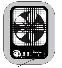 Manual Reset Limit Button
Warranty
For more effective and safer operation and to prolong the life of the heater, read the Owner’s Guide and follow the maintenance instructions. Failure to properly maintain the heater will void any warranty and may cause the heater to function improperly. Warranties are non-transferable and apply to original consumers only. Warranty terms are set out below.LIMITED FIVE-YEAR WARRANTY: Cadet will repair or replace any Hot One (RCP) heater found to be defective within five years after the date of purchase.These warranties do not apply:
- Damage occurs to the product through improper installation or incorrect supply voltage;
- Damage occurs to the product through improper maintenance, misuse, abuse, accident, or alteration;
- The product is serviced by anyone other than Cadet;
- If the date of manufacture of the product cannot be determined;
- If the product is damaged during shipping through no fault of Cadet.
- The use of unauthorized accessories or unauthorized components constitutes an alteration and voids all warranties. Refer to the Cadet website or call customer service at 855.CADET.US for a list of authorized accessories and components.
- CADET’S WARRANTY IS LIMITED TO REPAIR OR REPLACEMENT AS SET OUT HEREIN. CADET SHALL NOT BE LIABLE FOR DAMAGES SUCH AS PROPERTY DAMAGE OR FOR CONSEQUENTIAL DAMAGES AND/OR INCIDENTAL EXPENSES RESULTING FROM BREACH OF THESE WRITTEN WARRANTIES OR ANY EXPRESS OR IMPLIED WARRANTY.
- IN THE EVENT CADET ELECTS TO REPLACE ANY PART OF YOUR CADET PRODUCT, THE REPLACEMENT PARTS ARE SUBJECT TO THE SAME WARRANTIES AS THE PRODUCT. THE INSTALLATION OF REPLACEMENT PARTS DOES NOT MODIFY OR EXTEND THE UNDERLYING WARRANTIES. REPLACEMENT OR REPAIR OF ANY CADET PRODUCT OR PART DOES NOT CREATE ANY NEW WARRANTIES.
- These warranties give you specific legal rights, and you may also have other rights which vary from state to state. Cadet neither assumes nor authorizes anyone to assume for it, any other obligation or liability in connection with its products other than as set out herein.If you believe your Cadet product is defective, please contact Cadet Manufacturing Co. at 855.CADET.US, during the warranty period, for instructions on how to have the repair or replacement process. Warranty claims made after the warranty period has expired will be denied. Products returned without authorization will be refused.Parts and ServiceVisit cadetheat.com/parts-service for information on where to obtain parts and services.Reduce-Reuse-RecycleThis product is made primarily of recyclable materials. You can reduce your carbon footprint by recycling this product at the end of its useful life. Contact your local recycling support center for further recycling instructions.
 Reduce-Reuse-RecycleThis product is made primarily of recyclable materials. You can reduce your carbon footprint by recycling this product at the end of its useful life. Contact your local recycling support center for further recycling instructions.
MAINTAINING YOUR HEATER
Maintenance As Needed, or every six months minimum.
 WARNING: Any other service not detailed in this Owner’s Guide should be performed by an authorized service representative.
- Allow the heater to cool, then disconnect the power cord from the power supply. To disconnect the heater, turn control to “OFF”, then remove the plug from the receptacle.
- Remove the front diffuser grill by removing the four screws (one from each corner).
- Wash the grill with hot soapy water and dry, or use an air compressor to blow debris from grill louvers.
- While holding a fan (to avoid damage or bending), use an air compressor, hairdryer, or vacuum on a low cycle to blow debris through the outer cabinet louvers and finned elements.
- Vacuum or blow air inside the fan area without touching the elements.
- Carefully wipe off the fan blade without damaging or bending it.
- Replace diffuser grill and secure with screws.
Troubleshooting Chart
*CONSULT LOCAL ELECTRICAL CODES TO DETERMINE WHAT WORK MUST BE PERFORMED BY QUALIFIED ELECTRICAL SERVICE PERSONNEL. ALWAYS UNPLUG THE HEATER BEFORE SERVICING.
| symptom | problem |
Solution |
| The plug does not fit the receptacle. | 1. Heater is 240 volts requiring a 20 amp or 30 amp 240-volt receptacle (see Figure 1 in “INSTALLATION INSTRUCTIONS”). | 1. DO NOT alter the cord. Install the proper 240-volt receptacle (see Figure 1 in “INSTALLATION INSTRUCTIONS”).* |
| The heater does not operate. | 1. Heater is or has been blocked.2. Thermostat set too low.3. Circuit breaker not turned on.4. Loose plug connection.5. Defective manual reset limit. | 1. Remove obstruction. Push manual reset button found in the front lower panel.2. Turn the knob clockwise until a click sound is heard.3. Turn the circuit breaker on.4. Check plug connection.5. Replace manual reset limit.* |
| Elements heat, fan does not operate. | 1. Jammed fan blade.
2. Defective motor. |
1. Remove obstruction.2. Replace the fan motor.* |
| Heater fan operates,
but does not discharge warm air. |
1. Manual reset limit tripped.2. ON/AUTO switch is “ON” and thermo- stat setting is below actual temperature.3. Defective heater elements.4. Wire loose from elements.5. Temperature rise on the heater is 40°F. | 1. Allow the heater to cool, then push reset.2. Increase the thermostat setting; turn ON/AUTO switch to “AUTO”.3. Replace elements.*4. Check and correct loose wire.5. Close doors or windows. Provide additional insulation and/or heaters. Wait for the room to warm up. |
| The heater does not shut off. | 1. Heat loss from the area is greater than heater capacity.2. Defective thermostat.3. ON/AUTO switch in “ON” position. | 1. Close doors or windows. Provide additional insulation and/or heaters.2. Replace the thermostat.*3. Change the ON/AUTO switch to the “AUTO” setting. |
| Heater
discharges smoke. |
1. Dust, dirt, and lint accumulated inside the heater.2. Jammed blade. | 1. Clean heater. (See “MAINTAINING YOUR HEATER” section for instructions). Blow dirt accumulation off the heater with compressed air (air compressor recommended).2. Remove obstruction. |
| Manual reset limit trips repeatedly. | 1. Overheating.2. Overheating at shutdown.3. Overheating from excessive dust or dirt particles.4. Overheating due to elevation of location. | 1. Check all clearance requirements. A 6″ minimum clearance is required between the top of the heater and ceiling. Tilt top of heater down approximately 30 to 45 degrees toward your work area.2. Discontinue the use of a breaker to control the heater.3. Clean heater (See “MAINTAINING YOUR HEATER” section for instructions).4. Location elevation exceeds recommended 7500 feet. |
MAINTAINING YOUR HEATER (continued)
Parts List
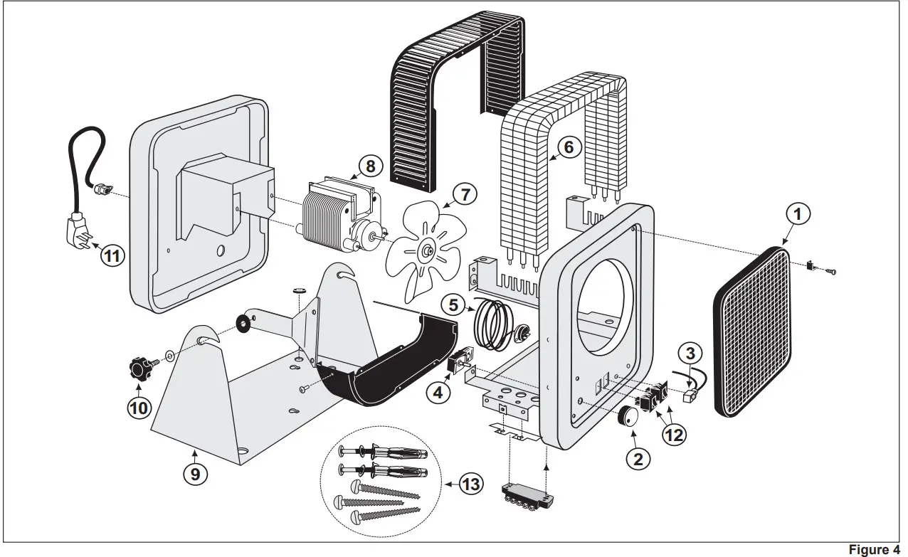
Note: Only the items listed below are available for purchase.
Parts List
| 1. 410102 Front Diffuser Grill Assembly with clips2. 040019 Thermostat Knob3. 050524 Pilot Light4. 051226 Thermostat5. 050327 Temperature Limit Switch6. 401723 Element, RCP402S 1333/1000W (3 req.)401726 Element, RCP502S 1667/1332W (3 req.)7. 001601 Fan Blade | 8. 051424 Fan Motor9. 400202 Mounting Stand10. 040023 Mounting Knob11. 051901 Cordset, RCP402S051903 Cordset, RCP502S12. 051707 Rocker Switch (HI/LOW)051708 Rocker Switch (ON/AUTO)13. 100740 Parts Package Mounting Screws |
Wiring Diagram
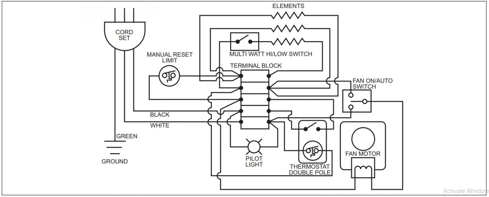
![]() SAVE THESE INSTRUCTIONS
SAVE THESE INSTRUCTIONS
cadetheat.com Tel: 855.CADET.US PO Box 1675 Vancouver, WA 98668-1675
©2016 Cadet Printed in USA Rev 03/16 #720086
References
[xyz-ips snippet=”download-snippet”]