![]()
Quick Reference Install Guide
REMOTE START with SECURITY & KEYLESS ENTRY SYSTEM
FOR PROFESSIONAL INSTALLATION ONLY!If you are not proficient in the installation of this product or would like a full version of the installation manual, please visit our web site @www.magnadyne.com
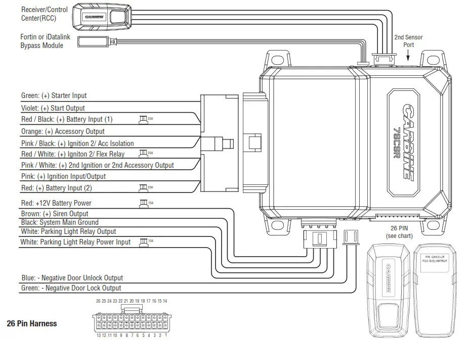
| Pin | Color | Function | Pin | Color | Function |
| 1 | WhiteNiolet | (-) 2nd Unlock Output | 14 | Black/Yellow | (-) Dome Light Supervision Output |
| 2 | Red/White | (-) Channel #3 Output | 15 | Blue/White | (-) 2nd Status or Rear Defog Output |
| 3 | Orange | (-) Ground When Armed | 16 | Dark Blue | (-) 1st Status Output |
| 4 | Brown | (+) Brake Switch Shutdown | 17 | Green/White | (-) Re-Arm the Factory Alarm Output |
| 5 | Gray | (-) Hood Pin Shutdown | 18 | Lt. Green/Black | (-) Disarm the Factory Alarm Output |
| 6 | Black/White | (-) Parking Brake Switch Input | 19 | Brown/Black | (-) Horn Output |
| 7 | Blue | (-) Instant trigger Trunk/Hood pin input | 20 | Orange/Black | (-) AUX Channel #6 Output |
| 8 | White/Blue | (-) External Activation Input | 21 | White/Black | (-) AUX Channel #5 Output |
| 9 | Gray/Black | (-) Diesel What to Start Input | 22 | Violet/Black | (-) AUX Channel #4 Output |
| 10 | Violet | (t) Door Trigger Input | 23 | Violet/Yellow | (-) Starter Output |
| 11 | Green | (-) Door Trigger Input | 24 | Orange/White | (-) Accessory Output |
| 12 | EMPTY | No Connection | 25 | Pink/White | (-) 2nd Ignition or Acc Output |
| 13 | Violet/White | (AC) Tach Input | 26 | Pink | (-) Ignition Output |
Mounting the Receiver/Control Center (RCC):
- Choose a location on the upper or sides of the vehicle windshield.A higher location is best.
- Remove the backing liner from the mounting tape on the backside of the RCC and stick it to the windshield glass.
- Route the RCC cable to the location of the control module.
Programming System Features:
All CARBINE remote start systems have a menu of features that can be programmed to suit the installation requirements of any vehicle. These features can be set by using the RCC button learning procedure or by Windows PC programming and the CARBINE web app. Feature Programming by RCC Button
- Open the driver’s door.
- Turn the ignition key ON then OFF.
- Within 5 seconds, press and hold the RCC button to select the menu.– A single chirp indicates Menu #1.– Hold the button longer for two chirps. You are in menu #2.– Continue holding the RCC button for three chirps. You are in menu #3.
- When the desired menu is reached, release the RCC button.
- Within 5 seconds, press and release the RCC button the number of times corresponding to the feature you want to change then press and hold the button once more to lock the feature. The siren / horn will chirp to match the feature selected. Release the RCC button.Note: RCC switch pushes are sequential. For example, if you start at feature #1, then push and release the valet switch 2 more times, you will be at feature #3 and so on. Always remember to push and hold the valet switch one more time after each selection to lock the feature before using the transmitter to change the setting.
- Use the
 or buttons on the CARBINE remote to adjust the feature.
 - For features with only two options, the (lock icon) = 1 Chirp setting, while the = 2 Chirp setting.
- For features with more than two settings, the button selects the settings in ascending order. Press and release the button as many times necessary to adjust the feature.
- The horn/siren will chirp indicating which setting is selected.
- Turn the ignition key to ON to exit feature programming.
Menu #1 (Default in Bold)
| Item | Feature | Chirps | ||||||
| 1 | 2 | 3 | 4 | 5 | 6 | 7 | 8 | 9 |
| 1 | Data Protocol | ADS | Fortin | |||||
| 2 | Confirmation Chirps | On | Off | |||||
| 3 | System Arming | Active | Passive | |||||
| 4 | Door LockingMode | Active | Passive | |||||
| 5 | Forced PassiveArming | On | OM | |||||
| 6 | Ignition KeyControlled Locking | Off | On | |||||
| 7 | Ignition KeyControlled Unlocking | Ott | On | |||||
| 8 | Panic with Ignition On | on | On | |||||
| 9 | Armed WhileDriving | Ott | On | |||||
| 10 | Auto StarterDisable | On | Ott | |||||
| 11 | Door Lock Pulse | 0.8 sec | 3.5 sec | 0.4 Sec | ||||
| 12 | Horn Output | 20 ms | 30 ms | 40 ms | 50 ms | Panic Only | ||
| 13 | Horn Honk mode | Pulsed | Constant | |||||
| 14 | Comfort Closure | Off | CC1 | CC2 | ||||
| 15 | Tilt Sensor Adjust | 3. | 1.5* | Off |
Menu #2 (Default in Bold)
| Item | Feature | Chirps | ||||||
| 1 | 2 | 3 | 4 | 5 | 6 | 7 | 8 | 9 |
| 1 | ProgressiveDoor Trigger | On | Ott | |||||
| 2 | Nuisance Pre-venbon Circuit | On | Ott | |||||
| 3 | Valet SwitchPulse Count forOverride | 1Pulse | 2Pulses | 3Pulses | 4Pulses | 5Pulses | ||
| 4 | Door TriggerError Chirp | On | on | |||||
| 5 | Double PulseUnlock | Off | On | |||||
| 6 | Double PulseLock | Off | On | |||||
| 7 | Ignition KeyControlledDome Light | On | Ott | |||||
| 8 | Siren Duration | 30 sec | 60 sec | |||||
| 9 | Factory AlarmDisarm withTrunk Release | On | 8 | |||||
| 10 | Factory AlarmDisarm Pulse | Single | Double | |||||
| 11 | Factory AlarmDisarm | With Unlock | Before UNlock | Remote Start Onty | ||||
| 12 | Channel #4Linking | None | Arm | Disarm | RemoteStart | |||
| 13 | Channel #4Output Type | ButtonHold | Latched | LatchedOtt withignition | 30sec | 60sec | 90sec | |
| 14 | Channel #5Linking | None | Arm | . Disarm | RemoteStart | |||
| 15 | Channel #5Output Type | ButtonHold | Latched | LatchedOff withignition | 30sec | 60sec | sN | |
| 16 | Channel #6 Linking | None | Arm | Disarm | RemoteStart | |||
| 17 | Channel #6Output Type | ButtonHold | Latched | LatchedOff with ignition | 30 Sec | 60sec | 90SEC |
Menu #3 (Default in Bold)
| Item | Feature | Chirps | ||||||||
| 1 | 2 | 3 | 4 | 5 | 6 | 7 | 8 | 9 | ||
| 1 | Transmission Type | Automatic | Manual | |||||||
| 2 | Engine CheckingMode | WirelessTach | Volta ge | WiredTach | off | |||||
| 3 | Cranking Duration | 0.6 Sec | 0.8 sec | 1.0 sec | 1.2 sec | 1.4sec | 1.6sec | 1.8sec | 2.0sec | 4.0sec |
| 4 | Remote Start RunTime | 12Minutes | 24Minutes | 60Minutes | ||||||
| 5 | Anti-Grind Output | On | Ott | |||||||
| 6 | Diesel Start Delay | WiredWait toStart | Tinier15 sec | Tinier35 sec | Timer45 sec | |||||
| 7 | ACC OutputDuring DieselWait to Start | Off | On | |||||||
| 8 | 2nd Ignition Behavior | Ignition 1 | Accessory | |||||||
| 9 | Blue/White WireFunction | GroundWhenRunning | Rear De-fog Latch10 min | RearDefogPulse | ||||||
| 10 | External RemoteStart Trigger PulseCount | 1Pulse | 2Pulses | |||||||
| 11 | Parking LightBehavior | Constant | Flashing | |||||||
| 12 | Timer Mode RunTime | 12Minutes | 3Minutes | 6Minutes | 9Minutes | |||||
| 13 | Turbo Timer RunTime | 1Minute | 3Minutes | 5Minutes | 10Minutes | |||||
| 14 | Timer Start Mode | TimerStart | TempStart |
- RCC switch pushes are sequential. For example, if you start at feature #1, then push and release the valet switch 2 more times, you will be at feature #3 and so on.
- Press and hold the RCC button after your selection. The siren/horn will chirp to match the feature selected.
- Use the and buttons on the remote to adjust the feature.
Access another menu
- Press and hold the RCC Button.
- After 3 seconds, the system will advance to the next menu and confirm with siren/horn chirps.
Exiting the feature program mode
- Set the ignition key to ON. A long confirmation chirp will be heard if a horn or siren is connected.
- Automatic after 30 seconds with no input from the RCC button (long chirp).
Feature Programming by PC/WebAll CARBINE Security and Remote Starter Systems with programmable features can programmed using a PC computer (excluding the 32CS model).
- A Windows computer with internet support is required. The web interface supports Windows 7 (sp1) thru Windows 10 operating systems (Apple/Mac computers are not supported)
- The web interface supports Microsoft Edge and Google Chrome browsers.
- The USB programming adaptor model #ALA-21P is required.
- Navigate to https://magnadyne.com/ala-21p-instructions and register an account.
- Follow the instructions provided on the webpage and install any dongle drivers or browser updates recommended.
Engine Checking Mode:The engine checking mode on all CARBINE remote start systems is set at “Voltage” by default. Once all the wiring is complete and correct, the engine can be remote started without any other changes. Engine type, Extreme weather etc. may require a more defined type of engine checking for reliable operation. Use the information enclosed to setup alternate engine checking modes.
Hardwire Tach or Data Tach
- Hardwire Tach requires the Lt.Violet/White wire to be connected to a fuel injector wire or a coil wire.
- Check the data bypass module spec to make sure it will provide a data tach signal. Additional pre-programming of the data module may be required. Refer to the data module instructions.
To learn the tach signal
- Start the vehicle with the key.
- Within 5 seconds, press and hold the valet button on the RCC.
- Once the tach signal is learned, the blue LED on the RCC will light or flash.– When tach learning from a hardwire connection, the parking lights will flash one time– When tach learning via the data module, the parking lights will flash two times.Note: Depending on the data bypass module used, you may have to put the bypass module into tach learning mode first before performing the above procedure. Review the instructions of the data bypass module before proceeding.
Wireless Tach Learning
To program Wireless Tach
- After the installation is completed, use the CARBINE key fob and initiate the remote start sequence.
- If the engine does not start on the first attempt, let the CARBINE module cycle and attempt to start the engine again. Up to (3) cranking attempts may be needed to start and run the engine.
- When the engine starts and runs, let it run for at least 30 seconds.
- Use the CARBINE key fob to shut down the engine. Wireless Tach is programmed.
Remote Start Shutdown DiagnosticsIf the remote starter activates but the engine fails to remain running, a diagnostic procedure can be run to try and determine where the fault in the system is.To Perform Shutdown Diagnostics
- With the ignition key Off, press and hold the RCC button.
- While holding the RCC button, turn the ignition key On then Off.
- Release the RCC button.
- Press and release the RCC button one time. The RCC LED will report the last shutdown reason for 1 minute or until the ignition key is turned On again. Compare the LED flashes to the chart below.
Status LED Flashes Reason for Shutdown 1 Over-Rev Shutdown 2 Runtime Expired 3 Shutdown by Transmitter (or Optional Push button) 4 Low or No RPM Detection 5 Hood Open Shutdown 6 (+) Brake Shutdown 7 (-) Parking Brake Shutdown 9 Low Vehicle Battery (Voltage Checking Mode Only) 10 Wait-to-Start 11 Alarm Trigger During Remote Start
Programming the Digital Shock Sensor:
Follow the enclosed procedure to set the sensitivity of the digital shock sensor.Note: The pre-warning sensitivity adjusts in proportion to the shock sensitivity.
- Set the system in disarmed mode.
- Turn the ignition key ON/OFF 3 times (ending in off).
- Within 5 seconds, press buttons together for 2 seconds.The horn/siren will emit (1) long chirp to indicate you are in Shock Sensor Sensitivity Adjustment Mode.
- To increase sensitivity, press the button. Each time you press the button you will hear (1) chirp. When you reach the MAX level adjustment, you will hear 1 short + 1 long chirp.
- To decrease sensitivity, press the button. Each time you press the button you will hear (2) chirps. When you reach the MAX level adjustment, you will hear 2 short + 1 long chirp.
- The shock sensor has 20 steps available for adjustment.The default setting is 10.
- To return the shock sensor back to it’s default setting, press and release the button. You will hear 3 chirps.
- During the process you can test by knocking: 1 short chirp – prewarn; 1 Long chirp – TRIGGERTo exit the Shock Sensor Sensitivity Adjustment Mode, turn the ignition key on. You will hear 3 long chirps.
Reset and Deletion:
If the programmable features need to be reset to default or the Wireless Tach feature needs to be reset for re-programming, follow the enclosed procedure.
- Open at least one door on the vehicle
- Turn the ignition key to the ON position
- Within 5 seconds, press and release the RCC button the number of times required below to perform the task.– Press and release the RCC button two times to delete all of the programmed remote controls.– Press and release the RCC button three times to delete all features programming back to their default settings.Note: This procedure does not erase Wireless Tach information.– Press and release the RCC button four times to erase all pre-learned Wireless Tach information.
- Once you have selected the function you want to perform, press and hold the RCC button. The RCC LED will flash and the horn will chirp (if connected) to confirm the functional step chosen. Do Not release the button.
- Press and release the button of a programmed remote. The horn will chirp to confirm the feature has been reset/deleted.
- Release the RCC button and turn off the ignition key. The siren/horn will chirp (if connected) to confirm exit.
GOVERNMENT REGULATIONS This device complies with Part 15 of FCC rules. Operation is subject to the following two conditions: (1) This device may not cause harmful interference, and (2) This device must accept any interference received, including interference that may cause undesirable operation.This equipment has been tested and found to comply with the limits for a class B digital device, pursuant to Part 15 of the FCC Rules. These limits are designed to provide reasonable protection against harmful interference in a residential installation. This equipment generates and can radiate radio frequency energy and, if not installed and used in accordance with the instruction manual, may cause harmful interference to radio communications. However, there is no guarantee that interference will not occur in a particular installation. tf this equipment does cause harmful interference to radio or television, which can be determined by turning the equipment OFF and ON, the user is encouraged to try to correct the interference by one or more of the following measures:
- Reorient or relocate the receiving antenna.
- Increase the separation between the equipment and receiver.
- Connect the equipment into an outlet on a circuit different from that to which the receiver is connected.
- Consult the dealer or an experienced radio / TV technician for help.
WARNING! Changes or modifications not expressly approved by the party responsible for compliance could void the user’s authority to operate this device.
Magnadyne Corporation1111 W. Victoria Street Compton CA 90210 (310) 735-2000For Warranty Information: Please Visit Our Website at www.magnadyne.comIM_QS-76CSR
References
[xyz-ips snippet=”download-snippet”]