
40MAQHigh Wall Ductless SystemSizes 09 to 36
Owner’s Manual
NOTE TO EQUIPMENT OWNER:
Please read this Owner’s Information Manual carefully before installing and using this appliance and keep this manual for future reference.For your convenience, please record the model and serial numbers of your new equipment in the spaces provided. This information, along with the installation data and dealer contact information, will be helpful should your system require maintenance or service.
| UNIT INFORMATIONModel # _______________________________Serial # ________________________________INSTALLATION INFORMATIONDate Installed ___________________________ | DEALERSHIP CONTACT INFORMATIONCompany Name: ______________________Address:_____________________________Phone Number:________________________Technician Name:______________________ |
Specifications subject to change without notice.
A NOTE ABOUT SAFETY
Any time you see this symbol in manuals, instructions and on the unit, be aware of the potential for personal injury. There are 3 levels of precaution:
- DANGER identifies the most serious hazards which will result in severe personal injury or death.
- WARNING signifies hazards that could result in personal injury or death.
- CAUTION is used to identify unsafe practices which could result in minor personal injury or product and property damage.
NOTE is used to highlight suggestions that will result in enhanced installation, reliability, or operation.
 WARNING
PERSONAL INJURY, DEATH, AND / OR PROPERTY DAMAGE HAZARDFailure to follow this warning could result in personal injury, death, or property damage.
Improper installation, adjustment, alteration, service, maintenance, or use can cause an explosion, fire, electrical shock, or other conditions which may causepersonal injury or property damage. Consult a qualified installer, service agency, or your distributor or branch for information or assistance. The qualified installer or service agency must use factory-authorized kits or accessories when modifying this product.
Read and follow all instructions and warnings, including labels shipped with or attached to the unit before operating your new air conditioner.
GENERAL
The high wall fan coil unit provides quiet, maximum comfort. In addition to cooling and/or heating, the high wall fan coil unit matched with an outdoor condensing unit filters and dehumidifies the air in the room to provide maximum comfort.
IMPORTANT: The high wall fan coil unit should be installed by authorized personnel only; using approved tubing and accessories. If technical assistance, service, or repair is needed, contact the installer. The high wall fan coil unit can be set up and operated from the remote control (provided). If the remote is misplaced, the system can be operated from the “Auto” setting on the unit.
Operating ModesThe high wall fan coil unit has five operating modes:
- FAN Only
- AUTO
- HEATING (heat pumps only)
- COOLING
- DEHUMIDIFICATION
FAN OnlyIn the FAN Only mode, the system filters and circulates the room air without changing room air temperature.
AUTOIn the AUTO mode, the system automatically cools or heats the room according to the user-selected set point.
NOTE: AUTO mode is recommended for use on single zone applications ONLY. Using AUTO CHANGEOVER on multi-zone applications could set an indoor unit to STANDBY mode, indicated with two dashes (–) on the display, which will turn off the indoor unit until all the indoor units are in the same mode (COOLING or
HEATING). HEATING is the system’s priority mode. SimultaneousHEATING and COOLING is not allowed.
HEATINGIn the HEATING mode, the system heats and filters the room air.
COOLINGIn the COOLING mode, the system cools, dries, and filters the room air.
DEHUMIDIFICATION (DRY)In the DEHUMIDIFICATION mode, the system dries, filters, and slightly cools the room air temperature. This model prioritizes air dehumidification but it does not take the place of a dehumidifier.
Wireless Remote ControlThe remote control transmits commands to set up and operate the system. The control has a window display panel that displays the current system status. The control can be secured to a surface when used with the mounting bracket provided.
Wired Remote Control (Optional)Refer to the Wired Controller manual.
24V Interface (Optional)Allows the control of the Ductless System with a third-party thermostat.
Smartphone Control (Optional)Capability to be controlled by a smartphone adding the Wi-Fi® Interface Kit KSAIF0301AAA (sold separately).
Specifications are subject to change without notice.
PART NAMES
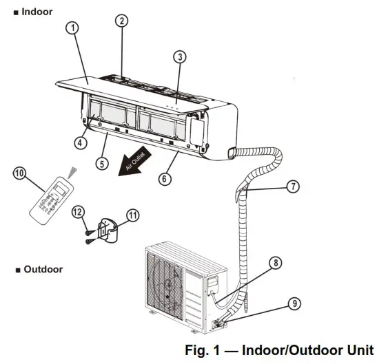
| 1. Front Panel2. Air Inlet3. Display4. Air Filter5. Right-Left Airflow Grille6. Up-Down Airflow louver | 7. Interconnecting Tubing8. Control and Power Wiringto Indoor Unit9. Service Valves10. Remote Control11. Remote Control Bracket12. Self-Tapping Screws |
INDOOR UNIT DISPLAY INDICATOR
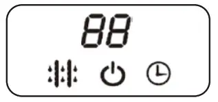
![]() SELECTED TEMPERATURE SELF-DIAGNOSTIC CODES INDICATOR
SELECTED TEMPERATURE SELF-DIAGNOSTIC CODES INDICATOR![]() DEFROST INDICATORIlluminates when the coil is warming up to prevent cold blow or when the unit goes into defrost mode.
DEFROST INDICATORIlluminates when the coil is warming up to prevent cold blow or when the unit goes into defrost mode.
![]() OPERATION INDICATORThis indicator flashes once per second after power is on and illuminates when the unit is in operation.
OPERATION INDICATORThis indicator flashes once per second after power is on and illuminates when the unit is in operation.
![]() TIMER INDICATORIlluminates during TIMER operation
TIMER INDICATORIlluminates during TIMER operation
![]() Displays temperature, operation feature and error codes:
Displays temperature, operation feature and error codes:
![]() for 3 seconds when:• TIMER ON is set• FRESH, SWING, TURBO, or SILENCE features are turned on
for 3 seconds when:• TIMER ON is set• FRESH, SWING, TURBO, or SILENCE features are turned on
![]() for 3 seconds when:• TIMER OFF is set• FRESH, SWING, TURBO, or SILENCE features are turned off
for 3 seconds when:• TIMER OFF is set• FRESH, SWING, TURBO, or SILENCE features are turned off
![]() when defrosting
when defrosting![]() when the unit is self-cleaning
when the unit is self-cleaning
![]() when 46°F(8°C) or 54°F(12°C) heating mode is turned on
when 46°F(8°C) or 54°F(12°C) heating mode is turned on
Fig. 2 — Display Panel
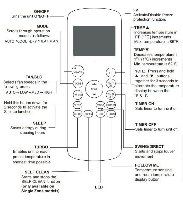
WIRELESS REMOTE CONTROL
Before you begin using your new air conditioner, familiarize yourself with the remote control.
, Turns indoor unit s LED display ON and OFF. If you are sensitive to light during sleep, you can press the LED button to turn off the LED display on the indoor unit. Press again to turn it back on.
Fig. 3 — Remote Controller Function Buttons
NOTE: New Remote Controller starting on production of week 41 year 2016 (serial number 4116V10001). For advanced functions, refer to the RG57F3(B)/BGEFU1 Wireless Remote Controller’s Service Manual.
WIRELESS REMOTE CONTROL LCD SCREEN INDICATORS
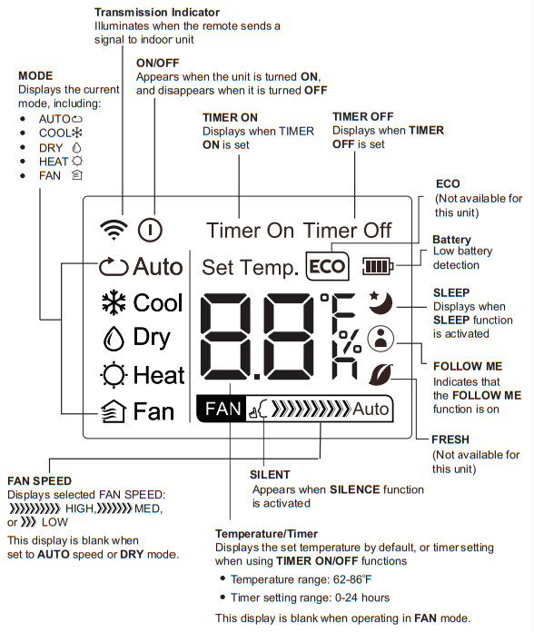
Fig. 4 — Wireless Remote Display
REMOTE CONTROL
CAUTIONEQUIPMENT DAMAGE HAZARDFailure to follow this caution may result in equipment damage. Handle the control with care and avoid getting the control wet.
IMPORTANT: The remote control can operate the unit from a distance of up to 26 ft. (8 m) as long as there are no obstructions. When the timer function is used, the remote control should be kept in the vicinity of the fan coil (within 26 ft. / 8 m).The remote control can perform the following basic functions:
- Turn the system ON and OFF
- Select the operating mode
- Adjust room air temperature set point and fan speed
- Adjust right-left airflow direction
Refer to the “INDOOR UNIT DISPLAY INDICATOR” on page 3 for a detailed description of all the capabilities of the remote control.
Battery InstallationTwo AAA 1.5v alkaline batteries (included) are required for remote control operation.
To install or replace batteries:
- Slide the back cover of the control to open the battery compartment.
- Insert the batteries. Follow the polarity markings inside the battery compartment.
- Replace the battery compartment cover.
NOTES:
- When replacing batteries, do not use old batteries or a different type of battery. This may cause the remote control to malfunction.
- If the remote is not going to be used for several weeks, remove the batteries. Otherwise, battery leakage may damage the remote control.
- The average battery life under normal use is about 6 months.
- Replace the batteries when there is no audible beep from the indoor unit or if the Transmission Indicator fails to light.
- When batteries are removed, the remote control erases all programmed settings. The control must be reprogrammed after the insertion of new batteries.
Remote Control Operation – Quick Start
NOTE: When transmitting a command from the remote control to the unit, be sure to point the control toward the right side of the unit. The unit confirms receipt of a command by sounding an audible beep.
- Turn the unit on by pushing ON/OFF.NOTE: If there is a preference for °C rather than °F (default), press and hold the + and – temperature setpoint buttons together for approximately 3 seconds.
- Select the desired mode by pushing MODE
 Fig. 5 —Modes
 - Select the temperature setpoint by pointing the control toward the unit and pressing the increase/decrease temperature set point buttons until the desired temperature appears on the screen.
- Press FAN to select the desired fan speed.NOTE: If the unit is operating in DRY or AUTO mode, the fan speed will be automatically set.
- Set the airflow direction. When the unit is turned on, the Up-Down airflow louvers default to the cooling or heating position. The user can adjust the horizontal Up-Down airflow louver position by pushing DIRECT or have continuous louver movement by pressing SWING.
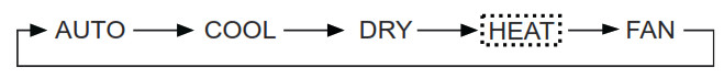 Fig. 5 —Modes
Manual Operation
If the remote control is lost, damaged, or the batteries are exhausted, MANUAL can be used to run the unit. When MANUAL is pressed once, the AUTO mode takes effect (heat or cool). When this button is pressed twice, the system enters the TEST mode and runs for 30 minutes in the COOLING mode (it will run in the AUTO mode afterward). When pressed three times, the system turns OFF.
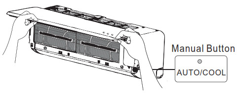
Fig. 6 — Manual Button
The set conditions of manual operation are as follows:• Preset set point: 76°F (24°C)• Fan speed: AUTODischarge air direction: Pre-set position based on operation inCOOL or HEAT mode.
REMOTE CONTROL FUNCTIONS
Pressing ON/OFF
When the air conditioner is not in operation, the remote control displays the last setpoint and mode.• Press ON/OFF to start the unit.– The unit starts in the last operating mode and set point. The ON/OFF indicator appears.• Press ON/OFF to stop the unit.– All the indicator lights on the unit go out, and the remote control displays the setpoint and mode.NOTE: If ON/OFF is pressed too soon after a stop, the compressor will not start for 3 to 4 minutes due to the inherent protection against frequent compressor cycling. The unit only emits an audible beep when the signals are received correctly.Selecting an Operating ModeUse OPERATING MODE to select one of the available modes.
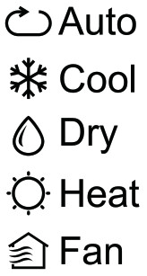
Fig. 7 — Operating Modes
Setting the Room Temperature SetPoint
Press the increased temperature set point ![]() and decrease
and decrease![]() buttons to raise or lower the temperature. The unit confirms the signal receipt with a beep and the value of the set temperature appears on the display and changes accordingly. The temperature can be set between 62°F (17°C) and 86°F (30°C) in increments of 1°F or 1°C.
buttons to raise or lower the temperature. The unit confirms the signal receipt with a beep and the value of the set temperature appears on the display and changes accordingly. The temperature can be set between 62°F (17°C) and 86°F (30°C) in increments of 1°F or 1°C.
NOTE: In the COOLING mode, if the temperature selected is higher than the room temperature, the unit will not start. The same applies for the HEATING mode if the selected temperature is lower than the room temperature.
Selecting the Fan Speed
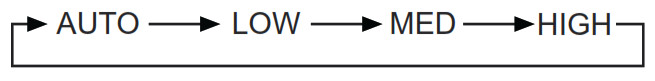
Fig. 8 — Fan Speeds
1. Press FAN to select the fan speed.
NOTE: When the unit is on, the fan runs continuously in cooling or heating. When in heating, there might be situations where the fan will slow down or shut off to prevent a cold blow.
Select the Up-Down Louver PositionTo optimize comfort, the Up-Down louver operates in a preset range.
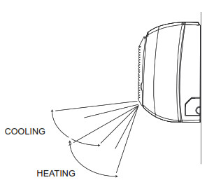
Fig. 9 — Louver Position
The up-down airflow louver can be adjusted by pressing DIRECT on the remote control and can be set to be stationary or moving continuously pressing SWING. The up-down louver position is stored in the settings, however, it is deactivated when the TURBO or MANUAL settings are set, or when a power interruption takes place.
Air DirectionPress DIRECT repeatedly to choose one of the up-down louver positions. Every time this button is pushed, the specific louver swings by 6 degrees.
In the COOLING, DRY, and FAN ONLY modes, the louver swings in the cooling range. In the HEATING mode, the louver swings in the heating range.
NOTE: Always use the remote control to adjust the up-down louver position, otherwise abnormal operation may occur. If the up-down louver is manually adjusted out of its range, power the unit off and then back on again.
Auto SwingFor automatic up-down louver swing, push SWING.
Select Right-Left Direction of the LouverThe right-left louvers can be adjusted manually to direct the airflow to achieve optimal comfort in the space.
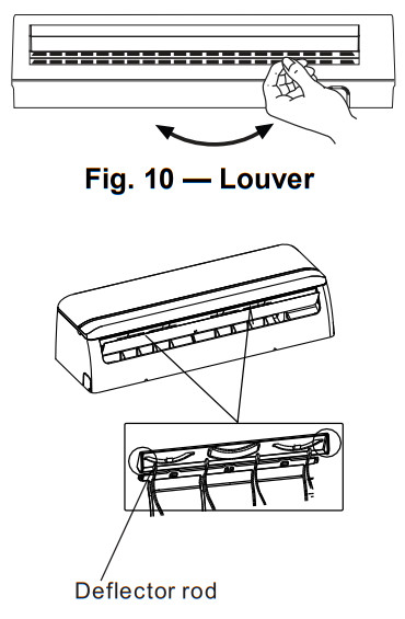 Fig. 11 — Deflector Rod
Timer Function
TIMER ON (to start the unit) and TIMER OFF (to stop the unit) can be used separately or together.
Timer ON Only ![]()
This function allows the unit to start automatically at the set time. TheTIMER ON function can be set while the unit is on or off.
UNIT ON ![]()
1. Press TIMER ON ![]() to initiate the auto-on time sequence. The set time is displayed in the remote control display. Every time TIMER ON is pressed, the time increases by 30 minutes, up to 10h. It increases by 60 minutes, afterward, until the time setting reaches 24h. When the TIMER ON is set, the TIMER light on the unit illuminates. The unit continues to run at the set time. TIMER ON
to initiate the auto-on time sequence. The set time is displayed in the remote control display. Every time TIMER ON is pressed, the time increases by 30 minutes, up to 10h. It increases by 60 minutes, afterward, until the time setting reaches 24h. When the TIMER ON is set, the TIMER light on the unit illuminates. The unit continues to run at the set time. TIMER ON
UNIT OFF ![]()
1. Set the timer described in the UNIT ON section. The unit starts at the set time.2. Adjust the TIMER ON settings to 0.0 to cancel this option.
Timer OFF Only ![]() This function allows the unit to stop automatically at the set time. The time can be set while the unit is on or while it is off.
This function allows the unit to stop automatically at the set time. The time can be set while the unit is on or while it is off.
UNIT ON ![]()
1. Press TIMER OFF ![]() to initiate the auto-off time sequence. The set time appears on the remote control display. Every time TIMER OFF is pressed, the time increases by 30 minutes, up to 10h. It increases by 60 minutes, afterward, until the time settings reach 24h. When the TIMER OFF is set, the timer light on the unit illuminates and the unit turns off automatically at the set time. TIMER OFF
to initiate the auto-off time sequence. The set time appears on the remote control display. Every time TIMER OFF is pressed, the time increases by 30 minutes, up to 10h. It increases by 60 minutes, afterward, until the time settings reach 24h. When the TIMER OFF is set, the timer light on the unit illuminates and the unit turns off automatically at the set time. TIMER OFF
UNIT OFF ![]() 1. Set the TIMER OFF as described in the UNIT ON section. The TIMER display on the unit illuminates and the unit remains off. ON/OFF2. Adjust the TIMER ON settings to 0.0 to cancel this option.
1. Set the TIMER OFF as described in the UNIT ON section. The TIMER display on the unit illuminates and the unit remains off. ON/OFF2. Adjust the TIMER ON settings to 0.0 to cancel this option.
Timer ON and Timer OFF ![]()
![]()
Use both functions to program the unit to turn on and shut off at specified times.
UNIT ON ![]()
1. Set TIME OFF as previously described.2. Set TIME ON as previously described. The unit turns off automatically at the set TIME OFF and turns on at the set TIME ON.
UNIT OFF ![]() 1. Set TIMER ON as previously described.2. Set TIMER OFF as previously described. The unit starts automatically at the set TIME ON and turns off at the set TIME OFF.
1. Set TIMER ON as previously described.2. Set TIMER OFF as previously described. The unit starts automatically at the set TIME ON and turns off at the set TIME OFF.
SLEEP Mode ![]()
SLEEP mode is used to conserve energy and can be used when the unit is in the COOL, HEAT, or AUTO mode only.
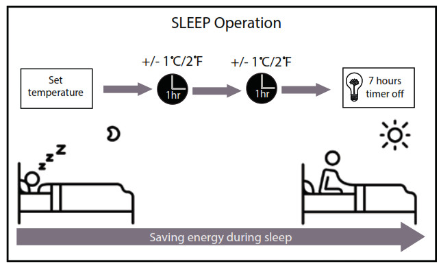
Fig. 12 — Sleep Mode
COOLING Mode ![]()
1. Push SLEEP. After 1 hour the setpoint raises by 1.8°F (1°C). After another hour, the setpoint raises by another 1.8°F (1°C) and the fan runs in a low speed. The unit shuts off 5 hours after setting the SLEEP mode. SLEEP mode cancels if either MODE, TEMP, FAN, TIMER, or ON/OFF on the remote control is pressed.
HEATING Mode ![]()
Same as the COOLING mode however the setpoints are lowered by 1.8°F (1°C).
TURBO Mode ![]()
Use TURBO to cool or heat the room rapidly.
1. Press TURBO. An audible “beep” is heard if the indoor unit supports this function. The fan runs at super high speed. The TURBO mode terminates automatically 20 minutes after selecting TURBO.2. To cancel TURBO, select TURBO mode again. When the TURBO mode terminates, the unit reverts to the original setting.
SELF CLEAN Mode ![]()
- Press CLEAN to activate or deactivate the self-cleaning function. Under this function, the air conditioner automatically cleans and dries the evaporator. The cleaning cycle takes 30 minutes, after which the unit turns off automatically. The unit operates in the following sequence:•FAN ONLY mode at LOW fan speed•HEATING operation with LOW fan speed•FAN ONLY operation•Stop Operation•Turn off
- To cancel the CLEAN mode, press CLEAN. The operation ends and the unit turns off. This function can be activated only in the COOL or DRY modes. Before selecting this function, it is recommended to run the air conditioner under COOLING1. Set TIMER ON as previously described.2. Set TIMER OFF as previously described. The unit starts automatically at the set TIME ON and turns off at the set TIME OFF. operation for about half an hour. Once the SELF CLEAN function is activated, all timer settings will cancel. The indoor unit displays SC.
NOTE: The SELF CLEAN mode is available ONLY on the single zone models.
FOLLOW ME Mode ![]()
Press FOLLOW to activate or deactivate this function. Under this setting, the temperature that appears in the remote control is the actual temperature at its location. The remote control sends this signal to the air conditioner every 3 minutes. This function is not available in the DRY and FAN modes. This function can also be deactivated if:
- No, FOLLOW ME signal is received by the unit for a continuous 7 min
- Users adjust the operation mode
- Users turn off the unit
- Users turn off the FOLLOW ME function
NOTE: If FOLLOW ME is used with the wireless remote controller, make sure that the remote’s IR sender is within line of sight of the IR receiver of the unit and is within the maximum range of 25 feet of the indoor unit. If FOLLOW ME is de-activated by pressing MODE, OFF, or FOLLOW ME on the remote, the icon on the remote will turn off.
Freeze Protection (FP) Mode ![]()
Press FP for approximately 2 seconds to activate or deactivate the freeze protection mode (heating set back). The indoor unit displays FP.
NOTE: This function is only available in the heating mode.
Under this function, the unit operates at high fan speed and the coil temperature automatically sets to 46°F (8°C). This mode can also be deactivated by pressing ON/OFF, SLEEP, MODE, FAN, or either TEMP.
SILENCE Mode ![]()
Press SLC to activate or deactivate the SILENCE Mode. Under this function, the compressor operates at low frequency and the indoor unit produces a faint breeze, which reduces the noise to the lowest level. Due to low the frequency operation of the compressor, it may result in insufficient cooling and heating capacity.
LED Light ![]() Press LED to turn the display light on and off.
Press LED to turn the display light on and off.
Resetting the Remote Control
If the batteries in the remote control are removed, the current settings will be canceled and the control returns to the initial settings and enters the STANDBY mode. Push ON/OFF to activate.
Time DelayIf ON/OFF is pressed too soon after a stop, the compressor will not start for 3 to 4 minutes due to the inherent protection against frequentcompressor cycling. The unit only emits an audible beep when the signals are received correctly.
Heating FeaturesIf the unit is in HEATING mode, there is a delay when the fan starts.The fan starts only after the coil is warmed up to prevent a cold blow.
Auto Defrost OperationIn the HEATING mode, if the outdoor coil is frosted, the indoor fan and outdoor fan turn off while the system removes the frost on theoutdoor coil. The system automatically reverts to normal operation when frost is removed from the outdoor unit.
Auto StartIf the power fails while the unit is operating, the unit stores the operating condition, and it will start operation automatically under those conditions when the power is restored.
Refrigerant Leakage DetectionThe indoor unit displays EC and the indication lamps continue flashing when it detects a refrigerant leak.
CLEANING, MAINTENANCE, AND TROUBLESHOOTING
CAUTION
ELECTRICAL SHOCK HAZARDFailure to follow this caution may result in personal injury or death. Always turn off power to the system before performing any cleaning or maintenance to the system. Turn off the outdoor disconnect switch located near the outdoor unit. Be sure to disconnect the indoor unit if on a separate switch.
CAUTION
EQUIPMENT DAMAGE/OPERATION HAZARDFailure to follow this caution may result in equipment damage or improper unit operation.Operating the system with dirty air filters may damage the indoor unit and could cause reduced cooling performance, intermittent system operation,frost build-up on indoor coil or blown fuses.
Periodic MaintenancePeriodic maintenance is recommended to ensure the proper operation of the unit. Recommended maintenance intervals may vary depending onthe installation environment, e.g., dusty zones, etc. Refer to Table 1 on page 12.
CAUTION
CUT HAZARDFailure to follow this caution may result in personal injury. The coil fins are very sharp. Use caution when cleaning.Always wear safety protection.
Cleaning the CoilClean the coil at the beginning of each cooling season, or when necessary. Use a vacuum cleaner or a long-bristle brush to avoid damage to the coil fins.
Cleaning the Air FiltersRemove and clean the air filters once a month. A clogged air conditioner can reduce the cooling efficiency of your unit, and can also be bad for your health.
NOTE: If air filters show signs of excessive wear or are torn, they must be replaced. Contact your local dealer for replacement filters.
- Lift the front panel of the indoor unit.|Fig. 13 — Lift the front panel
- Press the tab on the end of the filter to loosen the buckle, lift it up, then pull it towards you.
- Pull the filter out.Fig. 14 — Grab the filterFig. 15 — Pull the filter out
- If your filter has a small air freshening filter, un-clip it from the larger filter. Clean the air freshening filter with a hand-held vacuum.Fig. 16 — Air freshening filter
- Clean the large air filter with warm, soapy water. Be sure to use a mild detergent.Fig. 17 — Clean the filter
- Rinse the filter with fresh water, then shake off excess water.
- Dry it in a cool, dry place, and refrain from exposing it to direct sunlight.
- When dry, re-clip the air freshening filter to the larger filter, then slide it back into the indoor unit.Fig. 18 — Replace the filter
- Close the front panel of the indoor unit.
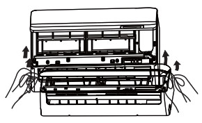 Fig. 13 — Lift the front panel
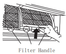 Fig. 14 — Grab the filter
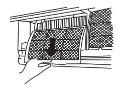 Fig. 15 — Pull the filter out
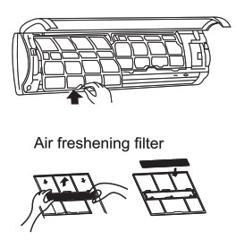 Fig. 16 — Air freshening filter
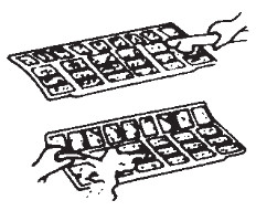 Fig. 17 — Clean the filter
CAUTION
EQUIPMENT DAMAGE HAZARDFailure to follow this caution may result in equipment damage. When cleaning the front panel, do not use water hotter than 105°F (40.6°C) and do not pour water onto the fan coil. Do not use abrasive or petroleum-based cleaners as they may damage the front panel.
Cleaning the Indoor Unit Front Panel
To clean the front panel on the indoor unit, wipe the outside with a soft, dry cloth.
Pre-Season InspectionAfter long periods of non-use, or before periods of frequent use, perform the following steps:
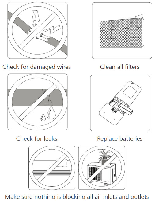
Fig. 19 — Pre-Season Inspection
Preparing for Extended Shutdown Period
Clean the filters and reposition them in the unit. Operate the unit in FAN ONLY mode for 12 hours to dry all internal parts. Turn the main power supply off and remove batteries from the remote control.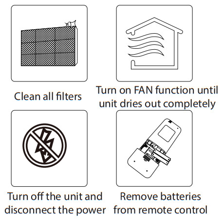 Fig. 20 — Extended Shutdown Period Steps
System Operation Recommendations
The items outlined in the following list help to assure proper system operation:
- Replace both remote control batteries at the same time.
- Point the remote control toward the unit display panel when transmitting a command.
- Keep doors and windows closed while unit is operating.
- Contact an authorized service representative if a problem arises that cannot be easily resolved.
- Do not perform cleaning or maintenance activities while the unit is on.
- Keep the display panel on the unit away from direct sunlight and heat as this may interfere with remote control transmissions.
- Do not block air intakes and outlets on the indoor or outdoor units.
Energy Saving RecommendationsThe following recommendations will add greater efficiency to the ductless system:
- Select a comfortable thermostat setting and leave it at chosen setting. Avoid continually raising and lowering the setting.
- Keep the filter clean. Frequent cleaning may be necessary depending on indoor air quality.
- Use drapes, curtains, or shades to keep direct sunlight from heating the room on very hot days.
- Limit the unit’s run time by using the TIMER function.
- Do not obstruct the air intake on the front panel.
- Turn on the air conditioning unit before the indoor air becomes too uncomfortable.
TROUBLESHOOTING
Refer to Table 2 before contacting your local dealer.
Table 1 — Periodic Maintenance
|
INDOOR UNIT |
EVERY MONTH | EVERY 6MONTHS |
EVERY YEAR |
| Clean Air Filter* | • | • | |
| Replace Carbon Filter | • | • | |
| Change Remote Control Batteries | |||
|
OUTDOOR UNIT |
EVERY MONTH | EVERY 6 MONTHS | EVERY YEAR |
| Clean Outdoor Coil from Outside | • | ||
| Clean Outdoor Coil from Inside | • | ||
| Blow Air Over Electric Parts | • | ||
| Check Electric Connection Tightening | • | ||
| Clean Fan Wheels | • | ||
| Check Fan Tightening | • | ||
| Clean Drain Pants | • |
* Increase frequency in dusty zones.† Maintenance to be carried out by qualified service personnel. Refer to the Installation Manual
Table 2 — Troubleshooting
|
PROBLEM |
POSSIBLE CAUSE |
SOLUTION |
| Unit/System Does Not Work | · The circuit breaker has tripped or a fuse has blown.· Diagnostic lights illuminate.*· Voltage is too low. | · Reset the circuit breaker or replace the fuse with the specified replacement fuse.· Call your service representative.· Call your service representative. |
| Cooling is Not Working Properly | · The filter is blocked by dust.· Temperature is not set properly.· A window or door is open.· The outdoor unit is obstructed.· The fan speed is too low.· The operation mode is in Fan instead of Cool. | · Clean the air filter.· Check the temperature and reset if necessary.· Close the window or door.· Remove the obstruction.· Change the fan speed selection.· Change the operating mode to Cool or reset the unit. |
| Heating is Not Working Properly | · The filter is blocked with dust.· Temperature is set too low.· A window or door is open.· The outdoor unit is obstructed. | · Check the temperature and reset if necessary.· Close the window or door.· Remove the obstruction. |
| Unit Stops During Operation | ·The Off timer is not operating correctly.·Diagnostic lights illuminate.* | · Restart the operating mode.· Call your service representative. |
 report this ad
* Diagnostic lights are a combination of lights that will illuminate in the display area on the unit. They are a combination of the lights you see during normal operation.Copyright 2020 Carrier Corp. D 3300 Riverwood Parkway Atlanta GA, 30339 Edition Date: 08/20Catalog No. OM-40MAQ-07Manufacturer reserves the right to discontinue or change at any time, specifications, or designs without notice and without incurring obligations.Replaces: OM-40MAQ-06
[xyz-ips snippet=”download-snippet”]