
Cartell CW-SYS Wireless Driveway System Instruction Manual
VERSION 1
WHAT’S IN THE BOX

- SENSOR “PUCK”
- INTEGRATOR
- AUGER SCREWS (2)
- CR123A BATTERIES WITH BATTERY CLIPS (2)
- 3’ (1 m.) COAXIAL CABLE
- TERMINAL BLOCK SCREWDRIVER
OPTIONAL
- 12VDC power supply(Part #CW-PSU)
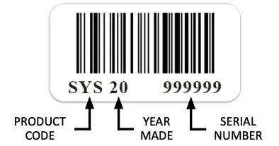
SERIAL NUMBER
There is a barcode serial number on the back of Integrator, bottom of puck, and on product box. When calling to talk about your product, please have one of these numbers handy.
INSTALLING BATTERIES/LOW BATTERY
- . Use CR123A batteries and match polarity with battery terminal in puck.
- If batteries are put in backwards, they will not make contact.
- Push batteries in place fully to make contact.
- Snap plastic battery holder over each battery and onto battery terminal.
- Sensor will power up automatically when batteries are installed.

LOW BATTERY
When batteries need replacing in sensor, Integrator will “chirp” and its LED will blink RED.
When hooked to external system’s zone inputs (see #10 below), program what you desire in order to indicate low battery.
REPLACE BOTH BATTERIES. DO NOT USE RECHARGEABLES.
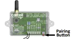
PAIRING
YOUR SYSTEM HAS BEEN PAIRED AT FACTORY. THESE DIRECTIONS APPLY WHEN PAIRING ADDITIONAL UNITS
You can pair up to 10 pucks with unlimited number of Integrators
- Bring sensor close to Integrator and power up Integrator (see #10 below).
- Push pairing button on Integrator (will stay in pairing mode 30 minutes).
- Power down & power up sensor by uninstalling and re-installing one battery (see #3 above).

- Integrator will beep 3 times when paired and exit pairing mode automatically.
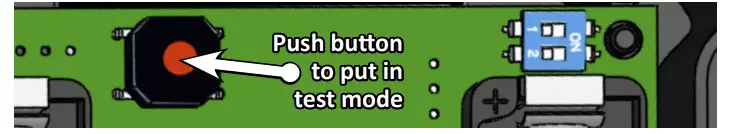
TEST MODE FOR SENSOR PUCK
Test mode allows the sensor puck to automatically transmit the radio signal without having to trip the sensor with a vehicle. This is useful when testing radio signal range (see #6 below).
- Press and HOLD button on sensor puck for 2 seconds
- The red LED will blink every second when in test mode
- There will be an immediate transmission
- Additional transmitions will occur every 10 seconds
- Test mode will be exited when button is pressed again for 2 seconds
- Test mode will automatically be exited after 30 minutes
TESTING RANGE
Your system has a radio range of at least 350 feet or over 1000’ line-of- sight. To determine range in your application, test before final installation.
Radio range depends on several variables:
- How the puck is installed (in ground or above ground on post)
- Obstacles blocking radio signal, such as soil, trees, foilage, buildings, concrete, etc.
To test range:
- Put Integrator near its final installation place in the home or gate.
- You will need to confirm the Integrator is sounding (see #9 below).
- Put sensor in test range mode (see #5 above).
- Listen for Integrator to trigger. If it doesn’t, move sensor closer to Integrator.
- Be sure to test again with puck installed in ground (see #8 below).
- You may need to add a repeater inside the home (see #9 below).
SETTING SENSITIVITY
ONLY ADJUST (LOWER) SENSITIVITY IF PUTTING IN MIDDLE OF DRIVEWAY (see #8 below). IN ALL OTHER CASES USE DEFAULT.

INSTALLING SENSOR PUCK

WARNING: SCREW HOLES IN PUCK WILL STRIP. DO NOT OVERTIGHTEN WITH SCREW GUN OR TAKE IN & OUT REPEATEDLY. IF SCREWS ARE STRIPPED, PURCHASE LONGER STAINLESS STEEL SCREWS, SUITABLE FOR PLASTIC.
The sensor puck can be installed in the driveway, in the ground or on an immovable object (post, tree, etc.).
ON AN OBJECT (see illustration bottom left)
- When range has been tested (see #6 above), seat lid securely on puck with screws provided. Be careful not to strip screws with screw gun. There should be no gap between lid and puck.
- Find a tree, post, or other object directly beside the driveway.
- Make sure the object is IMMOVABLE or false alarms will occur.
- Use the holes on the bottom tabs to screw puck to the object.
IN THE GROUND (see illustration bottom left)
- When range has been tested (see #6 above), seat lid securely on puck with screws provided. Be careful not to strip screws with screw gun. There should be no gap between lid and puck.
- Find a spot directly beside driveway.
- Dig a hole big enough for puck and auger screws, allowing puck’s lid to be level with surface of dirt.
- Secure puck in ground with auger screws, overlaping bottom tabs of puck. If you fail to secure puck, lawn mowers, etc. will pull/suck it up.
- Pack and tamp dirt around puck, ensuring lid is clean of dirt and all debris.
 IN FREE EXIT INSTALLATIONS, IF ANIMALS OR PEOPLE STEP ON SENSOR PUCK INSTALLED IN THE GROUND, IT MAY TRIGGER THE GATE TO OPEN. CONSIDER INSTALLING ON POST OR IN DRIVEWAY INSTEAD.
IN THE DRIVEWAY (see illustration bottom left)
- When range has been tested (see #6 above), seat lid securely on puck with screws provided. Be careful not to strip screws with screw gun. There should be no gap between lid and puck.Note: If close to cross traffic, consider turning sensitivity down (see #7 above)
- Use a 4.5″ diameter masonry hole saw to bore a hole for puck. Bore at least 2.75” deep so puck lid will be 1/4″ below driveway surface (so it can’t be pulled up by snow plows, graters, etc.).
- Pour loop sealant in hole, careful not to overfill, and put puck in hole.
- Hold puck down with weight until sealant becomes firm.
- DO NOT pour sealant over puck lid or bosses to gain access to batteries.
WARNING: KEEP LID FREE OF DIRT, GRASS, SNOW, & ALL DEBRIS AT ALL TIMES TO ALLOW RADIO SIGNAL TO TRANSMIT!
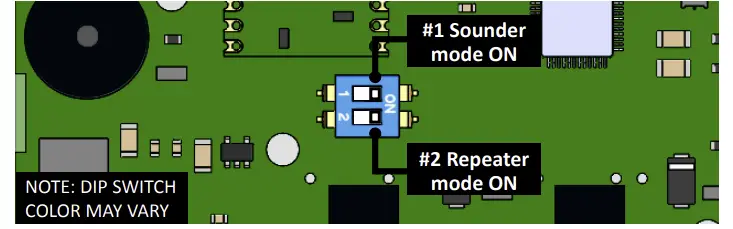
INTEGRATOR DIP SWITCHES
Dip switches control sounder and repeater mode on Integrator.
SOUNDER
Turn dip switch 1 ON to turn sounder on.
Sounder will beep 3 times when vehicle is detected. It will also “chirp” when sensor puck batteries are low and need replacing.
REPEATER MODE
Turn dip switch 2 ON to turn Integrator into a repeater. In repeater mode, the unit will continually receive and repeat any signal from the sensor to the Integrator installed in the home (see #11 below). Red and blue LED will alternately and continuously blink in repeater mode.
INSTALLING INTEGRATOR
Your system integrates seamlessly with any security/H.A. system or electric gate operator. NOTE: DO NOT USE WITH SOLAR GATES.
SECURITY/HOME AUTO SYSTEMS

Integrator uses 8-24 VAC or 8-30 VDC. Use security/H.A. system or gate operator to power or use any 12VDC power supply. Cartell sells optional power supply (Part #CW-PS).
YOU MUST ADD A SAFETY TO GATE WHEN USING CW-SYS FOR FREE EXIT.
AUTOMATIC GATE OPERATORS
DUAL EXIT TERMINAL
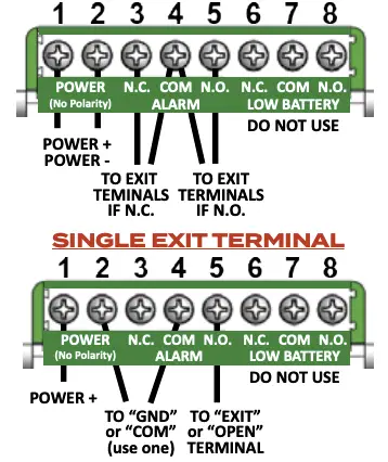
REPEATER MODE
To increase radio range, it may be necessary to make the Integrator a repeater.
If the signal from sensor puck is not reaching the Integrator:
- Move the sensor closer to the Integrator, and/or
- Install a repeater in the home between the sensor puck and Integrator connected to the security/home automation system. Do the following:
- Purchase an optional Integrator and power supply (Product CW-REP).
- Remove enclosure cover by carefully pushing side tabs in.
- Connect power supply to terminals 1 & 2 (no polarity).
- Turn dip switch 2 ON (see #9 above). This puts the unit in repeater mode. The red and blue LEDs will alternately blink to indicate repeater mode. It will continually receive every signal from the sensor and transmit (repeat) it to the Integrator installed beside the main system.
- Install repeater in a window closest to the sensor puck.
- Turn dip switch 1 OFF to turn sounder off.
NOTE: To order repeater kit, use product code CW-REP.

OPTIONAL EXTERNAL GATE ANTENNA
In gate operator installations, antenna attached directly to Integrator will work in most cases. The only time it may not work is in a sealed metal gate operator that blocks the RF signal. If that is the case, use the included coaxial cable and install antenna externally, per the following:
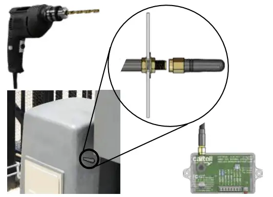
- Drill 1/4” hole in gate operator.
- Put female end of cable through hole and use nut to attach to operator. Make sure rubber gasket stays on outside between operator and washer.
- Screw antenna on male end of cable outside operator.
- Screw male end of cable to Integrator antenna connector.
RETURNING MERCHANDISE
CONSUMER: Contact your installer.
INSTALLER: CALL BEFORE DIGGING UP OR UNINSTALLING
Call (717) 532-0033, option 1 to troubleshoot and receive a Return Merchandise Authorization (R.M.A.) number. Write R.M.A. number on shipping box and any correspondence included with defective product.
DISTRIBUTOR: Send installers directly to Cartell, citing 717-532-0033 (option 1) as phone number.
WARNING: DO NOT SHIP BATTERIES WHEN RETURNING PRODUCT TO CARTELL.
FIVE YEAR WARRANTY
 All Cartell products are warranted against defects in material and workmanship for five years. This warranty does not cover defects caused by, but not limited to: acts of God, improper installation, abuse, fire damage, electrical surges, integrated system failures, improper lid/gasket/battery installation, overtightening screws, and stripping screw holes.
FCC WARNING
This device complies with part 15 of the FCC Rules. Operation is subject to the following two conditions: (1) this device may not cause harmful interference, and (2) this device must accept any interference received, including interference that may cause undesired operation. Any changes or modifications not expressly approved by the party responsible for compliance could void the user’s authority to operate the equipment.
NOTE: This equipment has been tested and found to comply with the limits for a Class B digital device, pursuant to Part 15 of the FCC Rules. These limits are designed to provide reasonable protection against harmful interference in a residential installation. This equipment generates, uses and can radiate radio frequency energy and, if not installed and used in accordance with the instructions, may cause harmful interference to radio communications. However, there is no guarantee that interference will not occur in a particular installation.
If this equipment does cause harmful interference to radio or television reception, which can be determined by turning the equipment off and on, the user is encouraged to try to correct the interference by one or more of the following measures:
- Reorient or relocate the receiving antenna.
- Increase the separation between the equipment and receiver.
- Connect the equipment into an outlet on a circuit different from that of thr receiver.
- Consult the dealer or an experienced radio/TV technician for help.
To maintain compliance with FCC’s RF Exposure guidelines, This equipment should be installed and operated with minimum distance between 20cm the radiator your body: Use only the supplied antenna.
IC Caution (Canada): This device complies with Industry Canada licence-exempt RSS standard(s). Operation is subject to the following two conditions: (1) this device may not cause interference; (2) this device must accept any interference, including interference that may cause undesired operation of the device.
This Class [B] digital apparatus complies with Canadian ICE-003.
The device has been evaluated portable device RF exposure requirements. The device is kept at least 5 mm away from the user’s body.


 report this ad
Copyright © 2020 by Cartell
References
[xyz-ips snippet=”download-snippet”]