Casio 5638 Watch User Manual
Working: -10~45℃℃, 5~85%RH without dew
Case materials: PC + ABS, fireproofProtection level: IP65 (Front side only)Dimension: W78 x H34.5 x D71 (mm)Installation drilling: W71 x H29 (mm)
Feature
ZL-7815A thermostat has two universal timer outputs: One timer output (R5) could be used as timer air exhaustion, and/or over temperature protecting exhaustion.Another timer has two outputs (R3/R4). It could control 2 wires motor, or 3 wires/2 direction motor.
Function
Besides the function introduced in Feature, it has: Heating / Cooling mode option, Temperature output delay protection,Over temperature warning, Buzzing hint and warning.
Specification
Power supply: 100 240Vac, 50/60Hz Sensor: NTC, R25 = 10K, B25/85 = 3435K Setting range: 1.0 ~ 75.0 Display range: -9.9 ~ 99.9 Terminal: 2*1.5mm2, or 1*2.5mm2Outputs (resistive specification): Temperature control R1 16A, R3/R4 3A, R5 5A
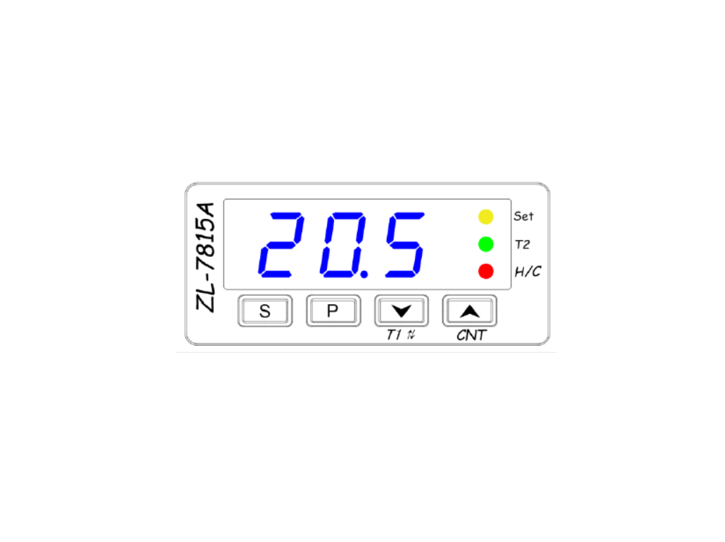
Keypad and Display Key
Key |
Function 1 |
Function 2 |
| P | Keep depressed for 3 sec. to set system parameters | |
| S | Keep depressed for 3 sec. to set set-point | |
| |
Set value down | Keep depressed for 5 sec. to switch timer 1’s outputs (R3/R4) status |
| |
Set value up | Short press to display for 2 sec. the times of R3 or R4 status changed. Lamp Set blinks in 2Hz |
Lamp
Lamp |
Function |
On |
Off |
Blink |
| Set | Setset-pointorsystem parameter | Settingset-point | —- | Slow blink: Setting system parameter Fast blink: the times of R3 or R4 status changes has reached U24. R3 and R4 will not switch any more |
| T2 | R5 status | R5 energized for T2 | R5 de-energized | R5 energized for over hot protection, ref. U16 |
| H/C | Temperature output | R1 energized | R1 de-energized | R1 under delay protection, ref. U12 |
Display Code
When there is problem, the code and the room-temperature will display alternatively.
Code |
Remark |
| E1 | Sensor failure, short or open |
| Hi | High temperature alarming |
| Lo | Low temperature alarming |
Power up (Reset) display
Display the following information consecutively: All units are on, Model name (78 15A), Software version (1.0):

Operation
Fast check
Keep ![]() 1 depressed for 5 sec. to switch the outputs (R3 and R4) status. Press
1 depressed for 5 sec. to switch the outputs (R3 and R4) status. Press ![]() CNT to display the counter value for 2 sec., and the Lamp Set blinks at 2Hz.The counter value counts the switching times of R3 or R4.
CNT to display the counter value for 2 sec., and the Lamp Set blinks at 2Hz.The counter value counts the switching times of R3 or R4.
Set set-point (factory default setting is 37.8
Keep ![]() key depressed for 3 sec.: Lamp Set on, the current set-point displays.Press
key depressed for 3 sec.: Lamp Set on, the current set-point displays.Press ![]() to set the new value. Keeping depressed can fast set.Press
to set the new value. Keeping depressed can fast set.Press ![]() to exit, and the setting will be saved.The status will exit, and the setting will be saved, if there is no key operation for 30 sec
to exit, and the setting will be saved.The status will exit, and the setting will be saved, if there is no key operation for 30 sec
Set system parameters
Keep “P” key depressed for 3 sec.: Lamp Set blinks, one system parameter code displays.Press ![]() to select a code.Press “S” to display the value of the code.Press
to select a code.Press “S” to display the value of the code.Press ![]() to set the value of the code. Keeping depressed can fast set.Press “S” to return to code display, for code selection.Keep “P” key depressed for 3 sec. to exit the status, and the settings will be saved.The status will exit, and the setting will be saved, if there is no key operation for 30 sec.
to set the value of the code. Keeping depressed can fast set.Press “S” to return to code display, for code selection.Keep “P” key depressed for 3 sec. to exit the status, and the settings will be saved.The status will exit, and the setting will be saved, if there is no key operation for 30 sec.
System parameter table
Code |
Function |
Range |
Remark |
Factory Set |
| U10 | Control mode | CO/HE | CO: Cool; HE: Heat | HE |
| U11 | Hysteresis | 0.1 ~ 20.0℃ | 0.1 | |
| U12 | Delay protection time for Temp. output (R1) | 0 ~ 999 sec | 0 | |
| U14 | Temp. high warning point (relative value) | 0.0 ~ 99.9℃ | If Room-temp ≥ Set-point + U14 warning (display Hi, buzzing); If Room-temp < Set- point + U14 stop warning 0.0: disable Temp. high warning function | 0.0 |
| U15 | Temp. low warning point (relative value) | 0.0 ~ 99.9℃ | Room-temp ≤ Set-point – U15 warning (display Lo, buzzing); Room-temp > Set-point – U15 stop warning 0.0: disable Temp. low warning function | 0.0 |
| U16 | Temp. high protecting point (relative value) | 0.0~20.0℃ | If Room-temp ≥ Set-point + U16, for U19 protecting exhausting on, R5 energized 0.0: disable Temp. high protecting function | 0.2 |
| U17 | Temp. high protecting hysteresis | 0.0~20.0℃ | Room-temp < Set-point + U16 – U17, protecting exhausting stops 0.0: disable Temp. high protecting function | 0.1 |
| U16 | Temp. high protecting point (relative value) | 0.0~20.0℃ | If Room-temp ≥ Set-point + U16, for U19 protecting exhausting on, R5 energized 0.0: disable Temp. high protecting function | 0.2 |
| U18 | 1st Temp. warning delay time | 0~600 min. | 0 | |
| U19 | Delay time for Temp. high protecting | 0~600 sec | 0 |
System parameter table (continued)
Code |
Function |
Range |
Remark |
Factory Set |
Timer 1 |
||||
| U20 | Time unit for R3 being energized | 0 ~ 2 | 0: sec.; 1: min.; 2: hour | 1 |
| U21 | Time for R3 being energized | 1 ~ 999 | 60 | |
| U22 | Time unit for R4 being energized | 0 ~ 2 | 0: sec.; 1: min.; 2: hour | 1 |
| U23 | Time for R4 being energized | 1 ~ 999 | 60 | |
| U24 * | Times for R3 or R4 being energized. | 0 ~ 999 | If U24 = 0, R3 and R4 never stop switching | 0 |
Timer 2 |
||||
| U30 | Time unit for R5 being energized | 0 ~ 2 | 0: sec.; 1: min.; 2: hour | 0 |
| U31 | Time for R5 being energized | 1 ~ 999 | 30 | |
| U32 | Time unit for R5 being de- energized | 0 ~ 2 | 0: sec.; 1: min.; 2: hour | 1 |
| U33 | Time of R5 being de-energized | 1 ~ 999 | 30 | |
| U34 | Working mode for R5 | 0 ~ 3 | 0: No function at all for R5 1: Timer 2 2: Temp. high protecting 3: Timer 2 + Temp. high protecting | 1 |
| U40 | Buzzing warning | 0 ~ 1 | 0: Shut down buzzing warning 1: Enable buzzing warning | 0 |
* Note: When set U24 a new value, the counter value of timer 1 will be reset to zero.Example 1: U24 = 200, the counter of timer 1 is 90, R3 or R4 status will still change 110 times. Now set U24 = 201, the counter will become 0, R3 or R4 status will change 201 times.Example 2: U24 = 200, the counter of timer 1 is now 200, R3 or R4 status will not change any more. Now set U24 = 201, the counter will become 0, R3 or R4 status wil vchange 201 times.
Control
Temperature controlCoolingIf Temp. ≥ Set-point + Hysteresis (U11), and R1 has been de-energized for protection time (U12), R1 will be energized. If Temp. ≤ Set-point, R1 will be de-energized.HeatingIf Temp. ≤ Set-point – Hysteresis (U11), and R1 has been de-energized for protection time (U12), R1 will be energized.If Temp. ≥ Set-point, R1 will be de-energized.Delay protection for R1After power supplied, R1 could be energized after protection time (U12) has passed.After R1 is de-energized, it could be energized again after protection time (U12) has passed.Timer 1, to control R3 and R4, set by U20 to U24R3/R4 switching counterThe counter counts the switching times. From the start of R3 on to next start of R3 on, it is one period, counter adds 1.If U24 = 0, R3/R4 will keep switching without stop. Else, when the counter value reaches U24, R3/R4 stops switching.Check the value of the counter: press ![]() CNT)), the value will display for 2 sec., and the Lamp Set will blink in 2Hz.Manually switching R3/R4Keep
CNT)), the value will display for 2 sec., and the Lamp Set will blink in 2Hz.Manually switching R3/R4Keep ![]() depressed for 5 sec. to switch outputs (R3 and R4) status.After switched, it will take full set time (U20 to U23) for next status switching
depressed for 5 sec. to switch outputs (R3 and R4) status.After switched, it will take full set time (U20 to U23) for next status switching
Multifunction R5
As timer 2 output (when U34 = 1 or 3) During the time set by U30 and U31, R5 will be energized. During the time set by U32 and U33, R5 will be de-energized.As temp. high protecting output (only in heating mode, when U34 = 2 or 3) If Temp. ≥ Set-point + U16 for U19 time, R5 will be energized. If Temp. < Set-point + U16 – U17, stop temp. high protecting
Temp. warning
When U40 = 0, no buzzing warning, only display warning code. After power supplied, the temp. warning will not be effective, until the U18 (1st Temp. warning delay time) time has passed. Temp. high warning If Temp. ≥ Set-point + U14, warning: beep, and display “Hi” and Temp. alternatively. If Temp. < Set-point + U14, stop warning. Temp. low warning If Temp. ≤ Set-point – U15, warning: beep, and display “Lo” and Temp. alternatively. If Temp. > Set-point – U15, stop warning.
Sensor
When the measured Temp. is not accurate enough, we could calibrate by setting the deviation to U13. When the sensor is not connected well, or broken, display “E1”, R1 will be de-energized. Do not install or dismount sensor under power supplied.
Buzzer Warning
When U40 = 0, there is no beeping warning, only display the warning code if any problem.When U40 = 1, there will be beeping warning, and display of warning code if any problem. Pressing any key could stop beeping.
Restore to Factory Default Settings
Keep P key and ![]() key depressed simultaneously for 3 seconds, controller displays “UnL”.Press
key depressed simultaneously for 3 seconds, controller displays “UnL”.Press ![]() key twice, all the settings will be restored to Fctory Set (see System parameter table).
key twice, all the settings will be restored to Fctory Set (see System parameter table).
InstallationInstallation
1st: Insert into drilling hole
2nd: Clamp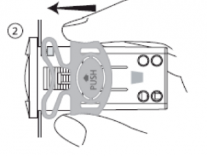
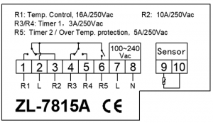
Wiring diagram
The parameter in the wiring diagram is resistant value
Read More About This Manual & Download PDF:
References
[xyz-ips snippet=”download-snippet”]