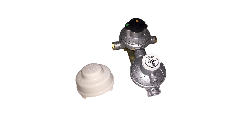
cavagna 528RV Double Stage Lowe Pressure Automatic Changeover Regulator Instruction Manual
WARNING
- Leaking gas can cause fires or explosions.
- Only trained personnel should work on gas systems.
- Inspect gas systems regularly.
- Replace regulators every 10 years or sooner, depending on the condition of the regulator.
SAFETY DEVICES
Protection device in case of overpressureThe overpressure value (2PSI; 140 mbar), which is accepted by the UL standard 144, in case of working problems or anomalies, is controlled by a safety device consisting of a flow limiter working together with a safety valve. This device keeps the over pressure value widely lower than the value expected by the standard without releasing, high quantities of propane gas into the atmosphere through the vent hole.
Protection device in case of an excess flow.The device “excess flow” assembled into the regulator operates (at 140% of the guaranteed flow rate) by limiting the gas flow to (50,000 BTU max.) in the event of a sudden increase in the desired flow, as in the case of hose rupture or accidental disconnection from the outlet of the regulator while in use.
IMPORTANT SAFETY INFORMATION
- All Cavagna product’ shall be installed in accordance with the National standards and utilised for their intended and correct use. In particular, for theAmerican requirements of the National Fire Protection Association pamphlets #54 # 58, DOT, ANSI and all applicable federal state, provincial and local standards, codes of practice, regulations and laws.
- It is the responsibility of the sellers, installation and maintenance personnel and the end user to be aware of and in compliance with all the applicable standards, codes of practice, regulations and laws.
- Always destroy damaged or worn regulators, pipes and parts so they cannot be reused.
- Cavagna regulators must be routinely inspected and replaced after 10 years of use. Regulators that are exposed to extreme heat, cold or other severe environmental conditions must be inspected and replaced more often as dictated by their condition and performance.
REGULATOR INSTALLATION GUIDELINES
- Blow out all the lines before installin the regulator. If foreign matter should become embedded in the regulator seat, it could cause high lockup pressure. The rising pressure could activate the pressure relief device inside the regulator. Make sure the lines to the regulator are free from all foreign matter.
- Connect the two Pig tail ends (1/4″ SAE inverted flare) to each of the regulator inlets, with the other end of the pigtails connected to the cylinder valves. Connect the regulator outlet to system service piping.
- The regulator should be installed with the 2 stage vent directed downward and /or under a covering to protect it from the ingress of rainwater.
- Before turning on any gas at the cylinder, make certain that any valves at the appliance are fully closed.
- Check each joint and connection for gas leaks by using an adequate foaming product.
CHANGEOVER OPERATION
 report this ad
The automatic changeover ensures continuous gas flow, automatically changing the gas withdrawal from the exhausted “service” cylinder to the full “reserve” one .The full-empty indicator assembled into the changeover handle indicates the exhaustion status of the “service” cylinder.The indicator colour changes from green to red, when the ”service” cylinder is exhausted.The rotation of the automatic changeover handle to the full “reserve” cylinder restores the green colour on the indicator.
TECHNICAL CHARACTERISTICS
- Gas Type: LPG
- Outlet Pressure: 11″ WC (28 mbar)
- Inlet Pressure (Max.): 250 PSI (17.50 bar)
- Operating Temperature: -20°C to 50 °C
- Body: Die cast Zinc alloy /painted
- Diaphragm: Approved NBR(fabric reinforced)
Support
Via Matteotti, 5Viadana di CalvisanoBrescia ITALYwww.cavagnagroup.corn
[xyz-ips snippet=”download-snippet”]