![]() Stealth Bomber Digital AmplifierBS1/BS2BS4/BS5Manual
Stealth Bomber Digital AmplifierBS1/BS2BS4/BS5Manual 
Introduction
Cerwin Vega Mobile AmplifierCongratulations for purchasing the Cerwin Vega Mobile amplifier for your car audio system. You have chosen Cerwin Vega Mobile because you deserve the best!Cerwin Vega Mobile amplifiers are designed and engineered to reproduce great sound quality for many years of listening enjoyment in your vehicle! We highly recommend that your new speakers be installed by an authorized Cerwin Vega Mobile dealer. Your authorized dealer can professionally assemble/disassemble the interior of your vehicle and set the proper amplifier placement for ideal sound quality.If you decide to install the amplifier by yourself, please thoroughly read through this manual before getting started. This manual will help familiarize you with these speakers and guide you through the installation process and procedures.Please contact your local authorized Cerwin Vega Mobile dealer if you have any questions regarding the instructions in this manual. If you require additional assistance, please contact the Cerwin Vega Mobile Technical Support Department during business hours at 213-261-4161We reserve the right to change the products and specifications at any time without notice. Images may or may not include optional equipment.
Installation
WARNING: Prolonged exposure to sound pressure levels in excess of 100dB can cause permanent hearing loss. Cerwin Vega Mobile amplifiers can exceed that level, so please exercise restraint when listening and enjoying your new amplifier.GENERAL PRECAUTIONS
- This unit is designed for negative ground 12V DC operation only.
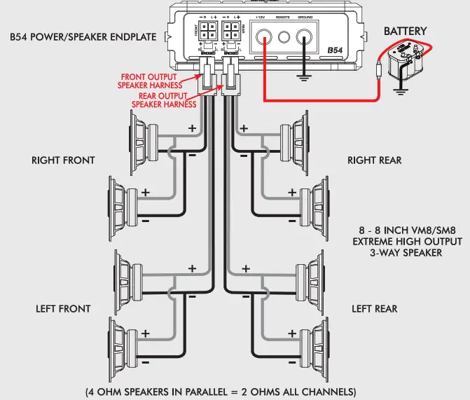
- Total system impedance must not be less than 2 Ohms stereo, or 1 ohm bridged for B51. B55 is minimum 2 ohms bridged on sub-channel (Ch5), and the B54/B55 (Ch 1, 2, 3, 4) is 4 ohms bridged
- Avoid installing the unit where: It would be subject to high temperatures, such as from direct sunlight or hot air from the heater. It would be exposed to rain, moisture, dust, and dirt.
- Do not cover the unit with carpet or wires.
- Do not use the unit with a weak auto battery. Optimum performance depends on the optimum battery supply voltage.
- For safety reasons, keep the volume of your car audio system moderate while driving your vehicle so that you can still hear normal traffic sounds outside your car.
- There is NO speaker level input connector, you can cut RCA’s and solder the wires and connect directly thru low-level input (RCA) or purchase the “optional ” RCA Adaptor cable to make a cleaner install, model -CHHILVL.
MOUNTING PRECAUTIONS
Although Cerwin Vega Mobile amplifiers incorporate heat sinks and protection circuits, mounting the amplifier in a fight space without any air movement can still damage internal circuitry over time. Choose a location that provides adequate ventilation around the amplifier. For easy system set-up, mount the amplifier so the side panel controls will be accessible after installation. To increase thermal run times on low impedance loads, an additional fan is recommended, remember any moving air across the amplifier will reduce heat. In addition, observe the following precautions:
- Using a felt pen, mark the mounting hole locations.
- Mounting the amplifier on the carpet will significantly reduce airflow, resulting in reduced thermal run times.
- Mount the amplifier on a solid surface. Avoid mounting to sub-woofer enclosures or areas prone to vibration. Do not install the amplifier on plastic or other combustible materials.
- Prior to mounting the amplifier, make sure not to cut or drill into the fuel tank, fuel lines, brake lines (under chassis), or electrical wiring.
WIRING PRECAUTIONS
- Before installation, make sure the source unit power switch is in the OFF position.
- Disconnect the negative (-) lead of the battery before making any power connections.
- When making connections, be sure that each one is clean and secure. Insulate all of your connections. Failure to do so may damage your equipment.
- A secure clean ground connection is critical to the performance of your amplifier. Connect the ground directly to the car chassis to minimize resistance and avoid any noise problems.
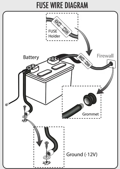
- Add an external fuse on the amplifier’s positive (+) power lead and connect it as close as possible to the vehicle’s (+) battery terminal. Use a rating that equals 1/2 the total current consumption at the full output of all amplifiers in the system. This external fuse will protect the vehicle from short circuits that can cause a fire.
Features
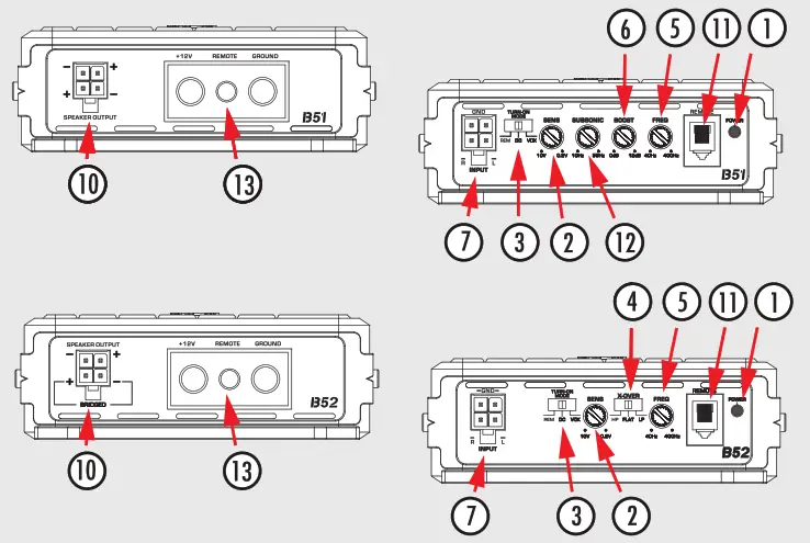
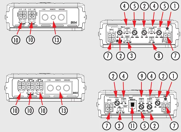
- Status LED’s — These lights indicate when the amplifier is powered up normally and when there is a NO protection fault.
- Sensitivity (Input Gain Adjustment) — This control matches the preamp stage of the (Erwin Vega Mobile amplifier to your source unit. This is NOT a volume control. The range is between approx. 200mV to 10V. It can ALSO handle speaker inputs of less than 25 watts RMS (typical OEM head units are LESS than 25W RMS…but NOT all)
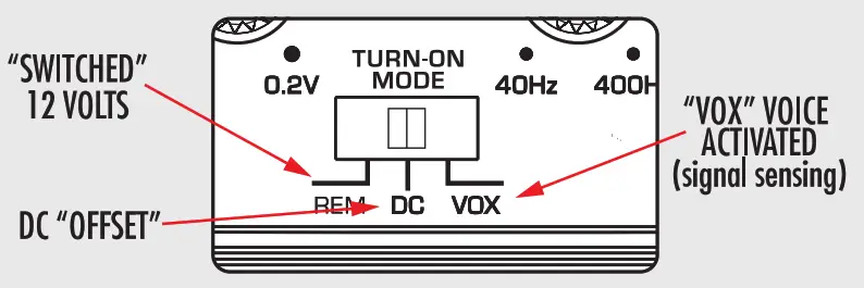
- TURN-ON OPTIONS — The BOMBER series of amplifiers can be switched on and off using one of three methods, determined by the position of the amplifier’s “Turn-On Mode” switch. Please read the “Set-Up ” portion of this guide and determine which is best suited for your specific system. NOTE: D( and VOX turn-on settings ONLY work with speaker level input.
- Crossover Selection Switch — This switch allows you to select the crossover Type. Use High Pass (HP) for mid-range or high-frequency speakers. Use Low Pass (LP) for subwoofers. In the FLAT position, neither crossover adjustment knob has an effect and at speakers will receive the full frequency range.
- LP/FULL/HP Crossover Adjustment — Use this adjustment to ADJUST the crossover type. Remember that you must select the High Pass position (HP) or the Low Pass (LP) or the FULL range position of the crossover adjustment switch first. The range of adjustment is limited between 40-400 Hz (B52- B54) and 70Hz front and rear FIXED on B55. Or FULL which passes ALL frequencies.
- Vega Bass Boost—This control adds 0 to +12dB of boost at 45Hz. Be cautious when adding a boost to some subwoofer systems as they may not be able to handle the additional low-frequency boost. In the OdB position, no bass boost is added.
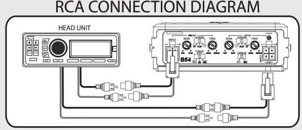
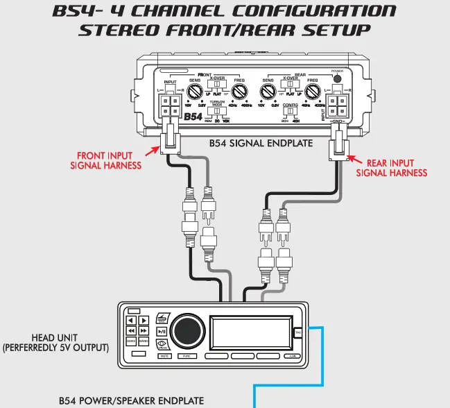
- RCA Input Harness — The RCA jacks allow for a normal Left and Right channel signal input. Simply conned to the source unit using RCA-type audio cables, keeping them away from power wiring wherever possible to reduce risk of noise.
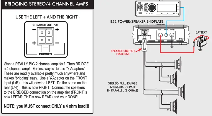
- 2/4 Channel Input Config — (B54 ONLY) Use this switch when you are using a stereo input ONLY and would like all 4 output channels on the B54 to have signal power output. Or when bridging stereo the B54 to make a BIG 2 channel high pass or a stereo subwoofer amplifier (4 Ohms only, stereo OR bridged).
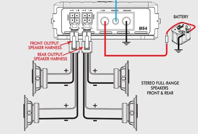
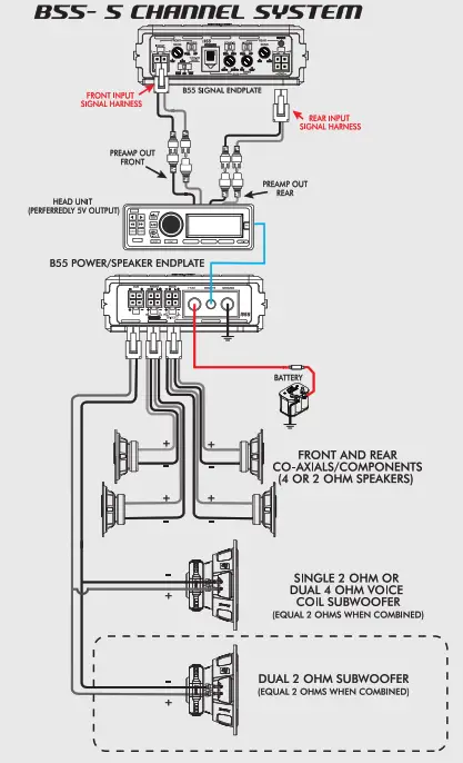
- Speaker Output Harness — Connect your speakers to these terminals. Stereo connections are connected as labeled. Bridged connections use the LEFT + and RIGHT – as the two connections. The 2 and 4 channel amplifiers will perform into 2 Ohm stereo loads or 4 Ohm bridged loads. DO NOT run 2 Ohm bridged loads on 852/B54 amplifiers! The 851 monoblock 1 Ohm mono, B55 subchannel 2 ohms minimum.3/5 Channel Input (config— (B55 ONLY) Use this switch when you are bridging stereo the front 4 channels to be a big 3 channel amplifier. Use the Front positive (+) and the Rear negative (-) for the bridged output (4 ohms ONLY!).
- Remote Level Control —1351/B52/B55 amplifiers have this port and is for the remote level control (included). The control is intended to allow the user to control the level of gain up to the maximum adjustment level set on the amplifier. The control does not add additional boost, it only attenuates the setting that is fixed at the amplifier’s control panel.
- Sub-Sonic Adjustment — This control is ONLY on the 851 and allows you to remove the unwanted sub-sonic frequencies below the tuning frequency of a ported enclosure. This helps to protect the woofer from over-excursion.
- Power Input Connections — These connections are for input power, chassis ground, and remote turn-on. Use a minimum of 8 gauge wiring for power and ground connections. 4 Gauge is recommended for the monoblock. The terminals will handle up to 8 gauge wiring with no problem whatsoever (4 gauge on the monoblock). Be sure any wiring that possesses through metal has a grommet!
Installation
VEHICLE ELECTRICAL SYSTEMAmplifiers (regardless of the brand name) will put an increased load on the vehicle’s battery and charging system. Cerwin Vega Mobile recommends checking your alternator and battery condition to ensure that the electrical system has enough capacity to handle the increased load of your stereo system. Original equipment electrical systems, which are in good condition, should be able to handle the extra load of any CVM amplifier without problems, although battery and alternator life can be reduced depending on your individual listening habits. To maximize the performance of your amplifier, we suggest the use of a reserve power “Stiffening” capacitor (1 Farad per 1000W) like the Cerwin Vega Mobile products CVCAP2.WARNING: Avoid running power wires near the low-level input cables, antenna, sensitive equipment or harnesses. The power wires carry substantial current and could radiate noise into the audio system through the audio cables.INSTALLATION:
- Plan the wire routing. Keep RCA cables close together but isolated from the amplifier’s power cables and any high-power auto accessories, especially electric motors. This is done to prevent coupling the noise from radiated electrical fields into the audio signal. When feeding the wires through the firewall or any metal barrier, protect them with plastic or rubber grommets to prevent short circuits. Leave the wires long at this point to adjust for a precise fit at a later time.
- Prepare the power wire for attachment to the amplifier by stripping 5/8 inch (15.9mm) of insulation from the end of the wire. Insert the bare wire into the B+ terminal and tighten the set screw to secure the cable in place.
 WARNING: The B+ cable MUST be fused 18″ or less from the vehicle’s positive battery post. Choose a location to install a waterproof fuse holder under the hood and ensure connections are watertight. If you do not use the appropriate fuse holder, the connection will eventually suffer corrosion from moisture and heat.
 - Trim the power cable within 18 inches (45.7mm) of the positive battery post and splice in an in-line fuse holder. DO NOT install the fuse at this time.
- Strip 1/2 inch (12.7mm) from the battery end of the power cable. Crimp and solder a large ring terminal to the cable. Conned the ring terminal to the positive (+) battery post.
- Prepare the ground wire for attachment to the amplifier by stripping 5/8″ of insulation from the end of the wire. Always use a wire of the same gauge as the power connection, never smaller. Insert the bare wire into the GND terminal and tighten the set screw to secure the cable in place. Prepare the chassis ground by scraping any paint from the metal surface and thoroughly cleaning the area of all dirt and grease. Strip the other end of the wire, crimp, and solder a ring connector. Fasten the cable to the chassis using a non-anodized screw with a star washer and a nut.WARNING: It is important to upgrade the ground connection between the negative (•) battery post and the vehicle body or chassis to achieve optimum electrical performance.
- Prepare the REMOTE turn-on wire for attachment to the amplifier by stripping 5/8 inch (15.9mm) of insulation from the end of the wire. Insert the bare wire into the REM terminal and tighten the set screw to secure the wire in place. Connect the other end of the REM wire to a switched 12-volt positive source. The switched voltage is usually taken from the source unit’s remote amp turn-on lead. If the source unit does not have this output available, the recommended solution is to wire to an accessory terminal in the car’s fuse block using a relay to isolate the amplifier from the vehicle’s accessory circuit. This however will turn the amplifier on and off with the ignition key, regardless of whether the car stereo is on or off.
- Securely mount the amplifier to the vehicle or amp rack. Be careful not to mount the amplifier on cardboard or plastic panels. Doing so may enable the screws to pull out from the panel due to road vibration or sudden vehicle stops.
- Conned the car speakers. Speakers impedance should never be less than 2 Ohms stereo, 4 Ohms bridged (the B51 monoblock is stable into 1 ohm). For most applications, 18 gauge wire is adequate for the speaker leads. For leads in excess of ten feet, 16 gauge wire is recommended. When wiring the speakers, pay careful attention to the polarity of the terminals on the speakers and make certain they correspond to the polarity on the amplifier. DO NOT chassis ground any of the speaker leads as unstable operation or damage to the amplifier and/or speaker may result.
 WARNING: The B+ cable MUST be fused 18″ or less from the vehicle’s positive battery post. Choose a location to install a waterproof fuse holder under the hood and ensure connections are watertight. If you do not use the appropriate fuse holder, the connection will eventually suffer corrosion from moisture and heat.
Set-Up
Placing the x-over switch in the FULL position (B52/B54) sets the amplifier to Full Range. This setting allows ALL frequencies to pass to the speakers. With the B52/B54, Placing the switch in the HP or LP position activates the 12dB crossover, adjustable from 40Hz – 400Hz. . The B51 mono is dedicated for Low Pass (LP) only with an adjustable frequency from 40Hz – 400Hz. The B55 (5 channel) amplifier offers full range (FULL) or high pass (HP) selector switch for channels 1-4. Selecting the high pass (HP) will activate a fixed 70Hz cross-over for full-range speakers. Channel 5 (on B55) is dedicated to subwoofers only but offers an adjustable (LP) crossover from 25Hz — 250Hz.
Placing the switch in the HP position sets the amplifier to the High Pass Filter mode, enabling frequencies above the cutoff point to pass. Placing the switch in the LP position sets the amplifier to the Low Pass Filter mode, enabling frequencies below the cutoff point to pass. For the system, tuning begin with the frequency set at approximately 80Hz and fine tune-up or down based on music choice and input level.To adjust the gain setting, turn the amplifier gains all the way down (counterclockwise). If using a remote level control (B51/B55), plug the level control into the amplifier and turn it to about “HALF-WAY” (approx. the 12 O’clock position) this setup the bass boost so you can turn it UP…OR…turn it UP or DOWN when playing different music styles. Next turn the source unit volume up to almost full volume (usually about 2/3rds of the way up) or until the output starts to distort on an oscilloscope. This will be NEARLY full volume on some source units, perhaps one or two “clicks” down from maximum volume. Next, increase the amplifier gain setting until the adequate volume is achieved, or until the distortion is audible and then turn it down a bit until the distortion is inaudible.NOTE: Ideal signal to noise and dynamic range are achieved with the gain at a minimum. Most users find adequate gain and volume is achieved at less than halfway in the adjustment range. Avoid setting the amplifier gain very high as noise and distortion will increase significantly. For a more in-depth level setting (gain adjustment) procedure, visit the (erwin Vega Mobile website.The HP or LP crossover adjustment can now be fine-tuned. If you are using the amplifier in an HP configuration and would like the system to be a little bit louder you can increase the HP Filter frequency and reset the “Gain” of the amplifier. Raising the HP frequency up to high, however, will cause a loss of mid-range and bass. If you are using the amplifier in a LP filter configuration and you hear voice or vocals coming from your subwoofer system you can turn the LP Filter frequency down (lower). After setting the input gain adjustment and crossover, you may choose to add a small amount of “Vega Bass Boost” (B51) in the low-frequency region. Remember that the Bass Boost feature will not fix a poorly designed subwoofer enclosure or subwoofers that didn’t sound good to begin with.
- Make sure any bass EQ or low-frequency equalization from the source unit is set to OFF or FLAT.
- While playing some musical selections used during the gain setting process, slowly increase the level of the Bass EQ. You should be able to notice a change between 0 and +12dB. If you do not notice much difference, then it will not serve any benefit to increasing the boost further.
- If the boost has audible benefits without adding appreciable distortion, find a level that suits your taste. Remember: it’s much easier to construct the right subwoofer enclosure for your listening preferences than relying on a bass boost control to do the job!
TURN-ON OPTIONS – configure the “Turn-On Mode” switch for desired turn-on trigger. There are 3 modes available on the Bomber series amplifier, REM, DC and VOX. (REM) is the standard 12V trigger wire (DC) or DC offset (when connected high level in, this will sense differences in the ground in your wiring through the speaker leads and turn on amplifier), VOX (signal sensing) will sense any kind of signal input into the amplifier RCA turning on the amplifier. The most preferred and reliable method is using the REM setting with a 12V trigger wire connected to the vehicle’s headunit switch output and will provide instant on and off for the amplifier. VOX and DC will provide turn-on capabilities for the amplifier when a 12V trigger wire is not available. These methods will have some delay in turning the amplifier on and off.
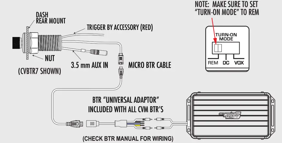
 OPTIONAL SOURCE – BLUETOOTH RECEIVER (BTR7/9/10/12) SETUPAll CVM amplifiers work with these Corwin Vega Mobile Bluetooth receivers: col, Va-

The BTR will pair to your phone (or any selected Bluetooth device) and will allow playback through the amplifier to speakers giving you unlimited installation options. The CVM line of BTR’s have 1 function-Play, Pause, Volume up/down, Track up/down, Pairing, and Power on/off of Bluetooth audio through this one solution. Once paired, the BTR will auto pair the last person paired to the controller when it was powered down. The unit will remember up to 9 users and have memory without a battery for up to 30 days.
System Configurations


Specifications
PRODUCT SPECIFICATIONS
| MODEL: | 651 | B52 | B54 | B55 |
| RMS Power Rating | 500 W RMS | 500 W RMS | 600 W RMS | 950 W RMS |
| Max Power | 1000 W | 1000 W | 1200 W | 1900 W |
| NS Power (2 0) | 300 W | 250WX2 | 150 WX4 | 150WX4/350WX1 |
| RMS Power (4 0) | 175W | 150WX2 | 80WX 4 | 80 V/ X 4/200 W X1 |
| Bridged (mono 1 01 | 500 W | N/A | N/A | N/A |
| Bridged (mono 2 0) | 300 W | N/A | N/A | N/A |
| Bridged (mono 4 0) | 175W | 500WX1 | 300WX2 | 300 Vi X 2/200 W X1 |
| Type | ||||
| Topology | Class 0 | Full Ronge (loss D | FullRange Class D | Full Ronge Class D |
| Power Supply | ||||
| Power Supply | Full PWM | Full PWM | Full PWM | Full PWM |
| Power Supply Threshold | 10.0VDC – 17.0VDC | 10.0VDC – 17.0VDC | 10.0VDC – 17.0VDC | 10.0VDC -17.0VDC |
| Idle Current | (0.7A) | (0.7A) | (0.7A) | (0.7A) |
| Distortion | ||||
| THD 4 (1KHz @4()) | 0.5% | 0.5% | 0.5% | 0.5% |
| S/N Ratio (A weighted @1W) | -85dBA | -85dBA | -85dBA | -85dBA |
| S/N Ratio (A weighted @ FP) | -101.1dBA | -101.1dBA | -101.1dBA | -101.1dBA |
| Input Sensitivity | ||||
| Low Input Level | 200mV -10.0V | 200mV – 10.0V | 200mV – 10.0V | 200mV -10.0V |
| High Input Level | 200mV – 10.0V | 200mV – 10.0V | 200mV – 10.0V | 200mV- 10.0V |
| Input Impedance | ||||
| Low Input Level | 20 KO | 20 KO | 20 KO | 20 KO |
| AUX Input Level | 20 KO | 20 KO | 20 KO | 20 KO |
| Output Stage | ||||
| Output Impedance | 0.0110 | 0.02970 | 0.0180 | 0.0180 |
| Damping Factor (50Hz © 40) | >250 | >250 | >70 | >70 |
| Bandwidth (-3dB) | 10Hz-350Hz | 10Hz-35KHz | 10Hz-35Hz | 10Hz-35Hz |
| Crossover (-12dB/Oct) | ||||
| Variable High-Pass | N/A | 40Hz – 400Hz | 40Hz -400Hz | Flat or Fixed 70Hz |
| Variable Low•Pass | 40Hz – 400Hz | 40Hz – 400Hz | 40Hz – 400Hz | 40Hz -400Hz |
| Variable Sub-Sonic | 10Hz – 55Hz | N/A | N/A | N/A |
| Fuse Ratings | ||||
| ATC | 25A | 25A | 40A | 60A |
| Dimensions | ||||
| Length x Width x Height(inches)Length x Width x Height(mm) | 7.7″ x 4.0″ x 1.4″ 195.6 x 102 x 36mm | 7.7″ x 4.0″ x 1.4″ 195.6 x 102 x 36mm | 8.8″ x 4.0″ x 1.4″ 225.6 x 102 x 36mm | 10.45″ x 4.0″ x 1.4″265.6 x 102 x 36mm |
Warranty
Please take a brief moment to register your new product. By registering your new product, you will receive benefits such as: Thank you for purchasing a Cerwin Vega Mobile product and we hope to provide you with countless hours of listening enjoyment.
- Important product notifications that may pertain to your purchase.
- Confirmation and record of ownership in case of loss or theft.
- Knowledgeable customer service and technical assistance pertaining to your product.
Register your new product by completely filling out this Product and Warranty Registration Card or register online at www.cerwinvegamobile.com.Registration is voluntary and failure to register will not diminish your limited warranty rights.Limited Warranty (U.S.A.)Cerwin Vega Mobile warrants all of our amplifiers and speakers to be free of defects in materials and workmanship for a period of one (1) year.This warranty is non-transferable and applies only to the original purchaser from an authorized Cerwin Vega Mobile dealer. If service is required and necessary under this warranty due to manufacturing defect or malfunction, then Cerwin Vega Mobile will repair and/or replace the defective products with either new or remanufactured products at no charge at our discretion.Damage to the product caused by the following will not be covered under this warranty: abuse, accident, misuse, neglect, modifications, repairing attempts, seller/installer misrepresentation.This warranty does not cover any incidental, consequential, or cosmetic damage due to accidents or normal wear and tear, nor does it cover the cost of removing or reinstallation of the product.Warranty is void if the product’s serial number has been removed, defaced, and/or tampered with.We recommend that you contact your Cerwin Vega Mobile authorized dealer where your original purchase was made to initiate all warranty claims. Our authorized dealers can guide you through the warranty procedure to ensure that your claim will be processed in a timely manner. All warranty returns must be accompanied with proof of purchase (a copy of the original sales receipt) and be shipped freight prepaid to our facility with an RA (Return Authorization) number clearly marked on the outside of the package. Direct returns from consumers or non-authorized dealers will be refused if shipped without a valid RA number authorized by Cerwin Vega Mobile beforehand. Warranty Procedure:INTERNATIONALProducts purchased outside of the U.S.A. are covered only by that country’s distributor and not by Cerwin Vega Mobile U.S.A.Please Ship All Warranty Claims With Pre-Authorized RA Number To: CV&DA Holdings, Inc.ATTN: Customer Service Department3761 S. Hill St.Los Angeles, CA 90007 USAPlease contact Customer Service for Further Warranty Information: U.S.A.Tel: 213-261-4161 / Fax: 213-947-4767We reserve the right to change the products and specifications at any time without notice.Images may or may not include optional equipment.
 report this ad
![]()
3761 South Hill StreetLos Angeles 90007, USAP 213-261-4161 / F 213-947-4767WWW.CEPWINVEGAMOBILE.COM©2019 Cerwin Vega Mobile All rights reserved. (a division of CV & DA Holdings, Inc.
[xyz-ips snippet=”download-snippet”]