
CHAMBERLAIN Wall Mount Garage Door Opener RJO70

WARNINGTo reduce the risk of SEVERE INJURY or DEATH, READ AND FOLLOW ALL INSTALLATION INSTRUCTIONS provided in the manual. This QuickStart is NOT intended to replace the manual, but serves as a reminder for those familiar with the manual and the installation of this product.
- The door WILL NOT CLOSE unless the Protector System® is connected and properly aligned.
- Periodic checks of the garage door opener are required to ensure safe operation.
Refer to the User’s Guide/Owner’s Manual for instructions on the use of your product, troubleshooting and periodic maintenance.
UNATTENDED OPERATIONThe Timer-to-Close (TTC) feature, the myQ® App and myQ® Garage Door are examples of unattended close and are to be used ONLY with sectional doors. Any device or feature that allows the door to close without being in the line of sight of the door is considered unattended close.
SAFETY INFORMATION
Safety SymbolsThis garage door opener has been designed and tested to offer safe service provided it is installed, operated, maintained and tested in strict accordance with the instructions and warnings contained in thismanual.
WARNINGWhen you see these Safety Symbols and Signal Words on the following pages, they will alert you to the possibility of serious injury or death if you do not comply with the warnings that accompany them. The hazard may come from something mechanical or from electric shock. Read the warnings carefully.
CAUTIONWhen you see this Signal Word on the following pages, it will alert you to the possibility of damage to your garage door and/or the garage door opener if you do not comply with the cautionary statements that accompany it. Read them carefully.
Before You Begin:
- Uninstall previous garage door opener.
- Disable locks.
- Remove any ropes connected to the garage door.
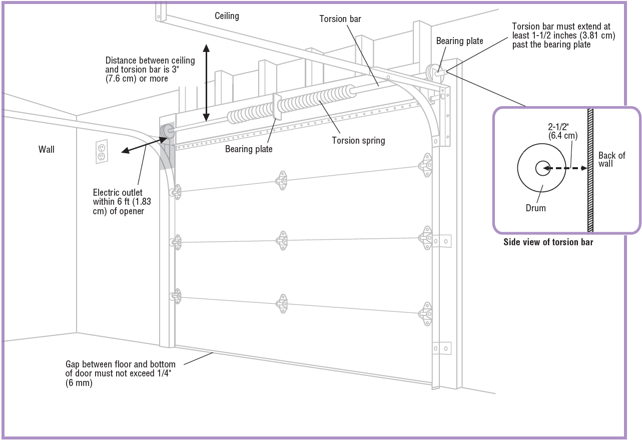
- Check the seal on the bottom of the door. Any gap between the floor and the bottom of the door must not exceed 1/4 inch (6 mm). Otherwise, the safety reversal system may not work properly.
Complete the test below to make sure the garage door is balanced and is not sticking or binding.
- Lift the door halfway up. Release the door. If balanced, it should stay in place, supported entirely by its springs.
- Raise and lower the door to check for binding or sticking.
If your door binds, sticks, or is out of balance, contact a trained door systems technician BEFORE you install this opener.To view a video showing how to balance your garage door, visit: https://tinyurl.com/ybpyxxzw
GLOSSARY
|
Term |
Definition |
| Bearing Plate | Acts as a support for the torsion bar. The bearing and mounting plate are typically located above the garage door. |
| Cable Tension Monitor | The cable tension monitor detects any slack in the garage door cables. Failure to properly install the cable tension monitor may cause the cables to be thrown and may result in a hazardous situation. |
| Door Seal | The door seal is located at the bottom of the door and helps to keep outdoor elements from entering the garage. |
| Drum | Drums are round, grooved spools on the torsion bar that keep door cables orderly. |
| Extension Springs | Extension springs are NOT compatible with this opener. Extension springs are typically mounted along the horizontal section of the track and extend from the front of the door opening to the back hang. The springs are intended to make a door lighter so you can easily open and close the door by hand. |
| High Lift Sectional Door | A type of garage door constructed with multiple panels that slide along a track inside the garage. The track runs vertically up the wall beyond the top of the door opening several inches before encountering the curve in the track. The extended distance above the top of the garage door determines the amount of a high lift. |
| Protector System® | The Protector System® is composed of a set of sensors and transmitters that act as a safety measure to prevent personal injury or property damage caused by a closing garage door. See also: Safety Reversing Sensor. |
| Roller | Small wheels which allow the door to move up and down the track. |
| Safety Reversing Sensor | The safety reversing sensors are a set of sensor eyes that detect obstructions in the path of the garage door. If an obstruction is found, the sensors tell the door to reverse direction. |
| Torsion Springs | A torsion spring is a type of spring that counter balances the garage door. The torsion spring is located above door on the torsion bar. The springs are intended to make a door lighter so you can easily open and close the door by hand. Consult a trained door systems technician if you need the springs adjusted or replaced. |
| Torsion Bar | A torsion bar is a horizontal metal bar mounted above the garage door. The torsion springs are located on the torsion bar. Most torsion bars are hollow, while some are solid. Some solid torsion bars may have a groove called a keyway that runs the length of the bar. |
WARNING
To prevent possible SERIOUS INJURY or DEATH:
- ALWAYS call a trained door systems technician if garage door binds, sticks, or is out of balance. An unbalanced garage door may NOT reverse when required.
- NEVER try to loosen, move or adjust garage door, door springs, cables, pulleys, brackets or their hardware, ALL of which are under EXTREME tension.
- Disable ALL locks and remove ALL ropes connected to garage door BEFORE installing and operating garage door opener to avoid entanglement.
CAUTION
To prevent damage to garage door and opener:
- ALWAYS disable locks BEFORE installing and operating the opener.
- ONLY operate garage door opener at 120 V, 60 Hz to avoid malfunction and damage.
PRE-INSTALLATION CHECKLIST
Your garage MUST meet the following requirements BEFORE you start installing the opener. You can install the garage door opener on either the left or right side of the garage door.Use the check list to see if your garage is compatible with the garage door opener requirements.IMPORTANT: If you DO NOT meet all the requirements contact a trained door systems technician.REQUIREMENTS CHECK LIST
- Sectional garage door:
- Standard sectional door up to 14 feet (4.3 m) high.
- Sectional High lift door (up to 54 inches (137.2 cm) high.
- Doors up to 18 feet (5.5 m) wide OR doors up to 180 sq. ft. (16.7 sq. m)
- Any gap between the floor and the bottom of the door must not exceed 1/4 inch (6 mm). Otherwise, the safety reversal system may not work properly.
- Torsion bar and torsion springs:
- Torsion bar is 1 inch (2.5 cm) diameter.
- Torsion bar must extend at least 1-1/2 inches (3.81 cm) past the bearing plate and be free of damage.
- Distance between ceiling and center of torsion bar is 3 inches (7.6 cm) or more.
- Distance between garage wall the torsion bar is mounted on and center of torsion bar is 2-1/2 inches (6.4 cm) or more.
- A minimum of 8.5 inches (21.6 cm) between the side garage wall (or obstruction) and the end of the torsion bar.
- Drums
- NOT compatible with reverse wound drums.
- must be 4-6 inches (10-15 cm) diameter.
- 3 to 3.9 inch (7.6cm 9.9cm) drums may be used on doors up to 430lbs (194kgs).
- Power
- An electric outlet must be accessible within 6 feet (1.83 m) of the installation area for the opener. The outlet must be 120 Vac – 60 Hz and 1.5 AMP current ONLY. Contact a qualified electrician if you need an outlet installed.
ALL the requirements above MUST be met. If you do not meet the requirements, contact a trained door systems technician.
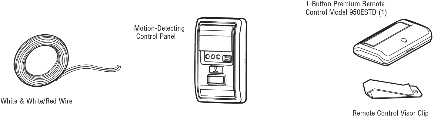
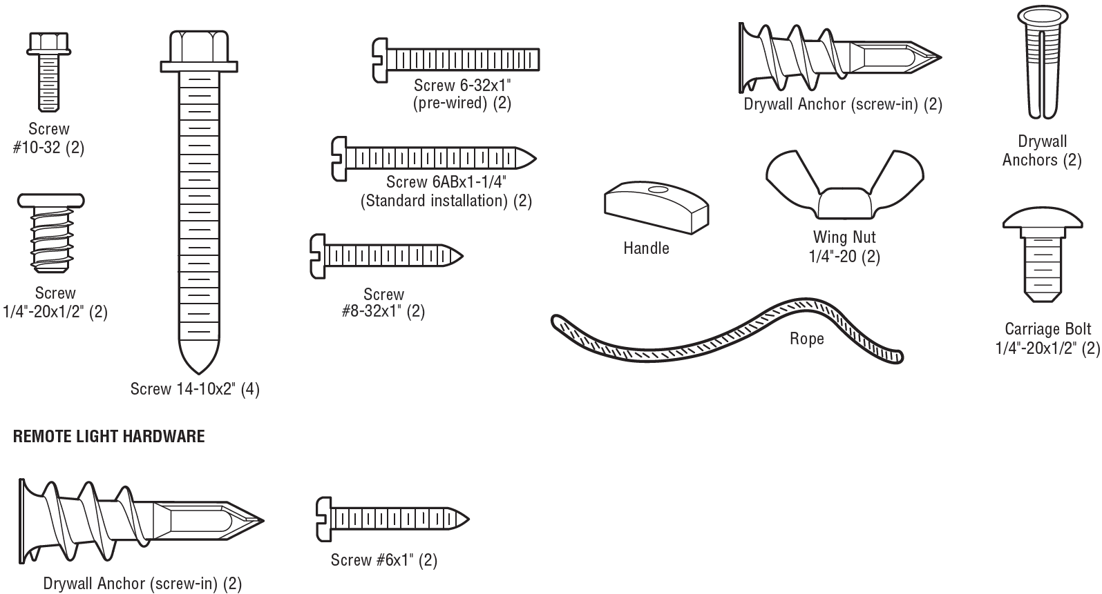
CARTON INVENTORY
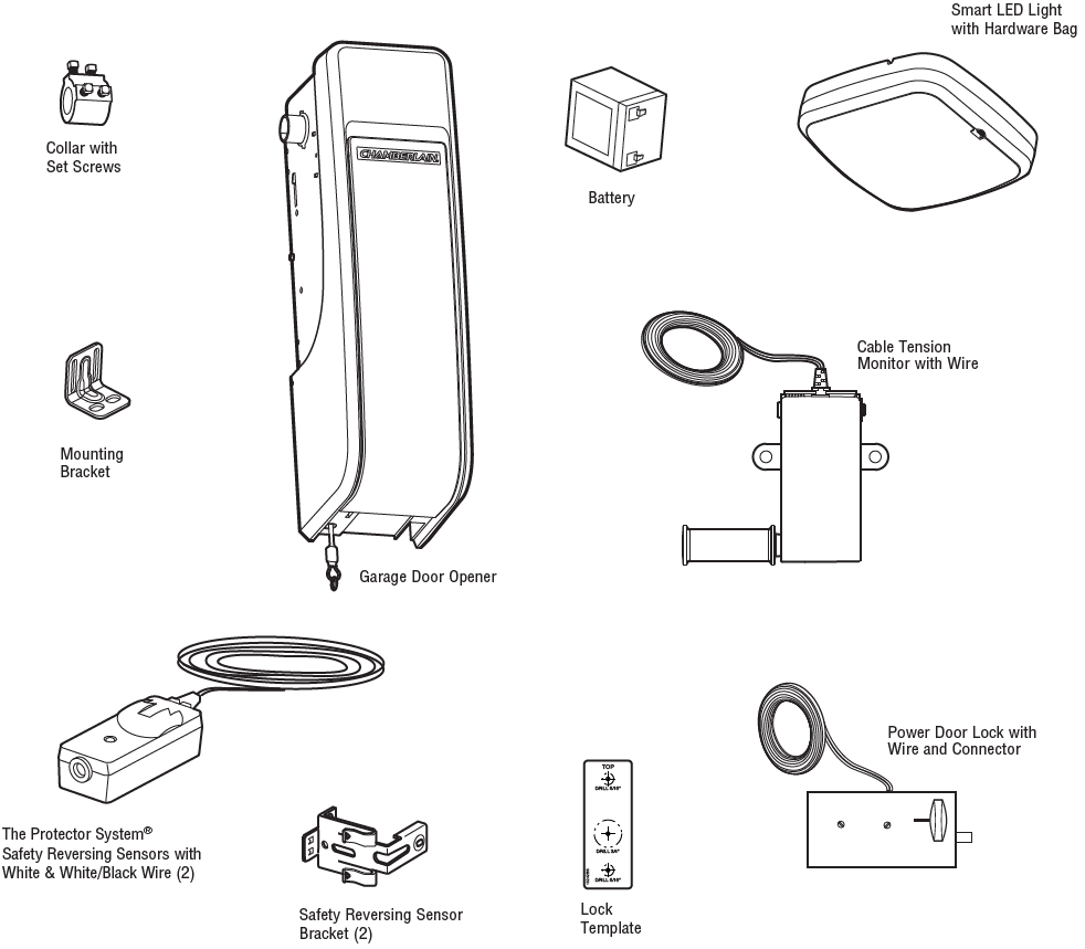
ACCESSORIES
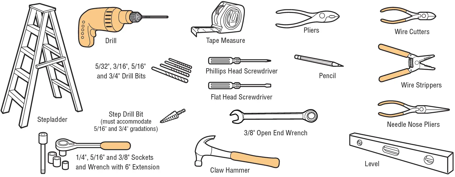
TOOLS REQUIRED
HARDWARE
INSTALLATION
To reduce the risk of SEVERE INJURY or DEATH:
- Read and follow all warnings and instructions.
- Install garage door opener ONLY on properly balanced and lubricated garage door. An improperly balanced door may NOT reverse when required and could result in SEVERE INJURY or DEATH.
- ALL repairs to cables, spring assemblies and other hardware MUST be made by a trained door systems technician BEFORE installing opener.
- Disable ALL locks and remove ALL ropes connected to garage door BEFORE installing opener to avoid entanglement.
- Where possible, install the door opener 7 feet (2.13 m) or more above the floor.
- Mount the emergency release within reach, but at least 6 feet (1.83 m) above the floor and avoiding contact with vehicles to avoid accidental release.
- NEVER connect garage door opener to power source until instructed to do so.
- NEVER wear watches, rings or loose clothing while installing or servicing opener. They could be caught in garage door or opener mechanisms.
- Install wall-mounted garage door control:
- within sight of the garage door.
- out of reach of small children at a minimum height of 5 feet (1.53 m) above floors, landings, steps or any other adjacent walking surface.
- away from ALL moving parts of the door.
- Install the emergency release marking. Attach the marking on or next to the emergency release. Install the entrapment warning placard next to the door control in a prominent location.
- Place emergency release/safety reverse test label in plain view on inside of garage door.
- Upon completion of installation, test safety reversal system. Door MUST reverse on contact with a 1-1/2″ (3.8 cm) high object (or a 2×4 laid flat) on the floor.
- To avoid SERIOUS PERSONAL INJURY or DEATH from electrocution, disconnect ALL electric and battery power BEFORE performing ANY service or maintenance.
- SAVE THESE INSTRUCTIONS.
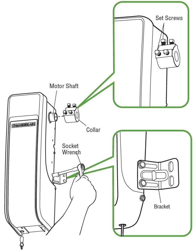
STEP 1: Attach the Collar to the Garage Door Opener
The garage door opener can be installed on either side of the door. The illustrations shown are for installation on the left side.
- Loosen the preset collar screws with the 3/8″ open end wrench.
- Slide the collar onto the garage door opener motor shaft until it stops.
- Securely tighten the 2 square head set screws closest to the motor shaft by hand, then turning the screws 1/4 – 1/2 turn.
- Loosely attach slotted side of mounting bracket to the same side of the garage door opener as the collar, using screws provided. NOTE: Do not tighten mounting bracket screws until instructed.
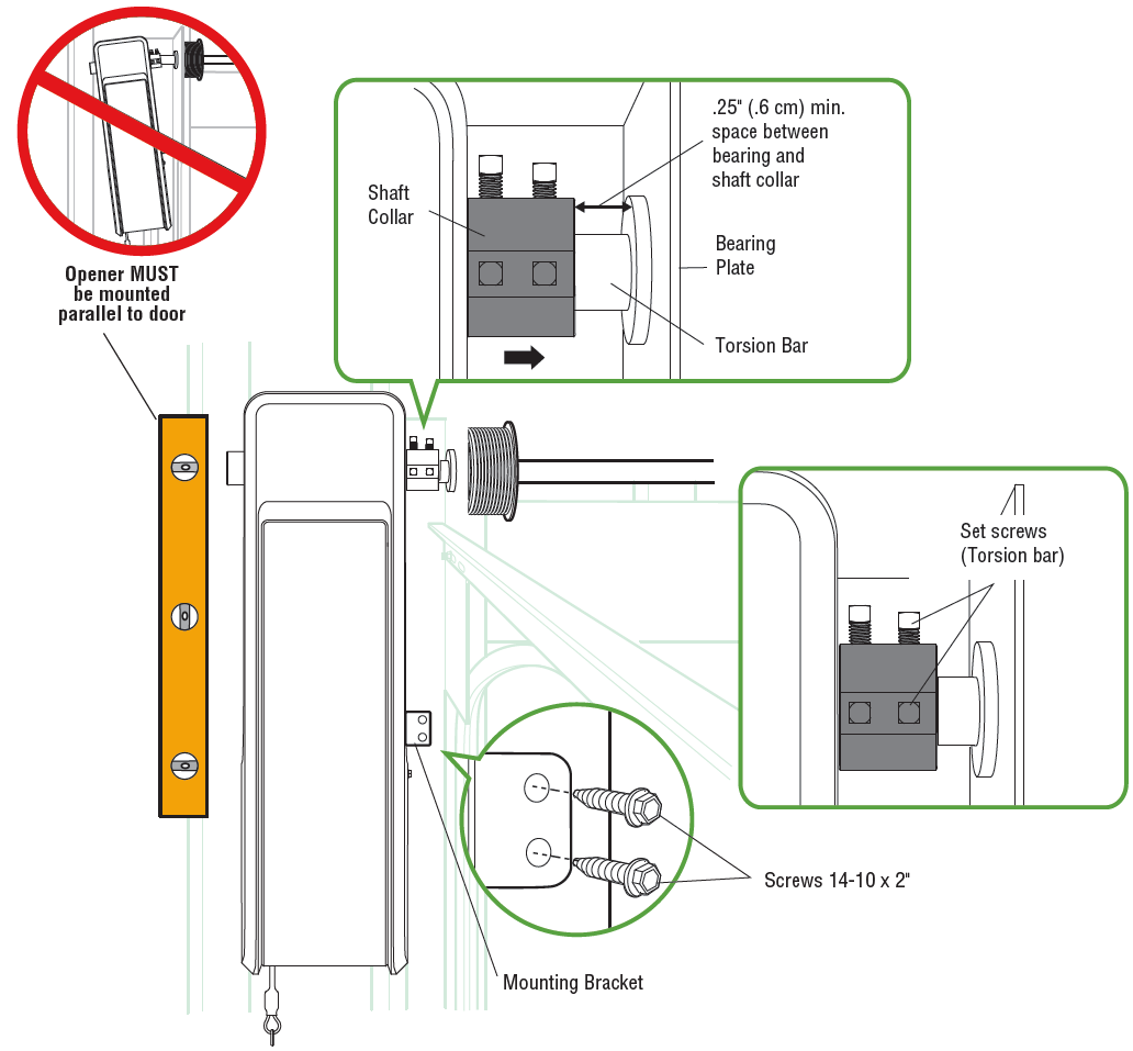
STEP 2: Position and Mount the Garage Door Opener
- Close the garage door completely.
- Slide the garage door opener onto the end of the torsion bar. Ensure the collar does NOT touch the bearing plate.
- Use a level to align the garage door opener parallel to the door. Verify the mounting bracket installation wall is solid surface, such as wood, concrete or a door/flag bracket.IMPORTANT: If installing on drywall, the mounting bracket MUST be attached to a stud.
- Mark the mounting bracket holes. If necessary, tighten collar screws on the torsion bar to hold garage door opener in place while marking holes.NOTE: The garage door opener does not have to be flush to the wall.
- Remove the garage door opener from torsion bar.
- Drill 3/16 inch pilot holes at the marked locations.
- Slide the garage door opener back onto the torsion bar.
- Tighten the 2 square head set screws on the torsion bar. For a hollow torsion bar, tighten screws 3/4 – 1 full turn after making contact with the bar. For a solid shaft torsion bar, tighten screws 1/4 – no more than 1/2 turn after making contact with the shaft. If installing on a keyed torsion bar, DO NOT tighten the screws into the keyway.
- Secure the mounting bracket to the wall and to the garage door opener.
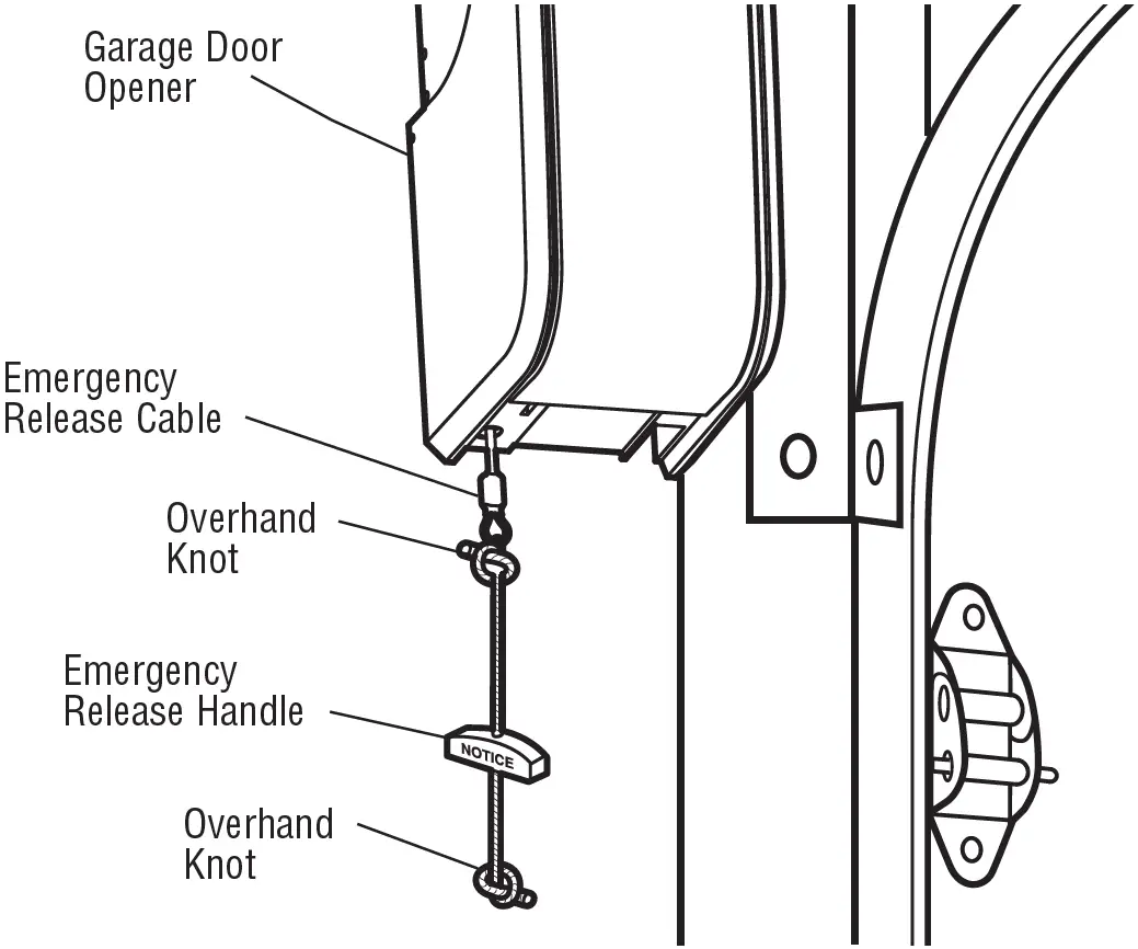
STEP 3: Attach the Emergency Release Rope and Handle
- Thread one end of the rope through the hole in the top of the red handle so “NOTICE” reads right side up. Secure with an overhand knot at least 1 inch (2.5 cm) from the end of the rope to prevent slipping.
- Thread the other end of the rope through the loop in the emergency release cable. Adjust rope length so the handle is no higher than 6 feet (1.83 m) above the floor. Secure with an overhand knot and cut off any excess rope.
- Place emergency release/safety reverse test label in plain view on inside of door.
NOTE: If it is necessary to cut the rope, heat seal the cut rope end with a match or lighter to prevent unraveling.
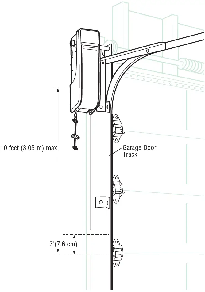
STEP 4: Power Door Lock Location
- Determine where to install the power door lock.
- Mount the door lock on the same side as the opener. The second roller from the bottom is ideal for most installations.
- The power door lock MUST be mounted within 10 feet (3.05 m) of garage door opener with approximately a 3 inch (7.6 cm) distance between the center of a door roller and the hole for the power door lock bolt.
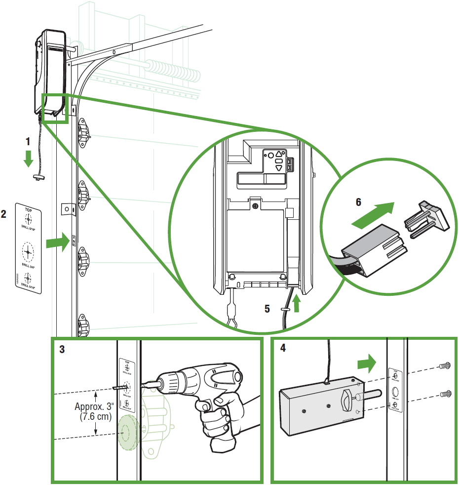
STEP 5: INSTALL POWER DOOR LOCK
- Pull down on the manual release to disengage the door and open the door manually.
- Clean inside track surface, and attach lock template to the track.
- Drill holes as marked on the template. You may find it useful to pre-drill the holes with a smaller bit before proceeding to larger sizes, or use a step drill bit.
- Fasten power door lock to the outside of the garage door track by hand-tightening the 1/4″-20×1/2″ screws provided.
- Run wire up wall to garage door opener. Use insulated staples to secure wire in several places.
- Insert wire through the bottom of the garage door opener and plug the connector into the garage door opener.
STEP 6: ATTACH THE CABLE TENSION MONITOR (REQUIRED)
The cable tension monitor detects any slack in the garage door cables. The cable tension monitor should be installed on the same side as the garage door opener. Factory default is configured for left-side installation.Determine if the cable tension monitor will be installed of the left or right side of the door. NOTE: Test the location of the cable tension monitor by opening and closing the monitor to see if the action would interfere with the door travel. The cable tension monitor will appear slightly open with the correct installation.
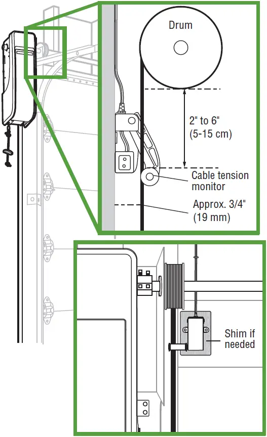
POSITION THE CABLE TENSION MONITOR
- Make sure the door cable is approximately 3/4″ (19 mm) from the mounting surface.
- Position the cable tension monitor as close to the drum as possible (2″ to 6″ (5-15 cm) from the from the bottom of the drum).
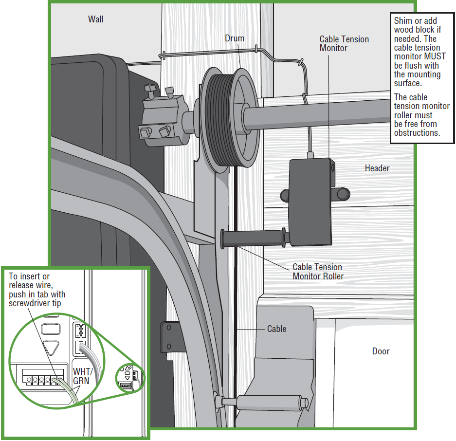
- Shim or add wood block if needed.
- The bracket MUST be flush with the mounting surface.
If the cable tension monitor cannot be mounted into wood, it can be mounted into 1/2 inch (1 cm) or greater drywall using the drywall anchors (2) and the #8 screws (2) provided in the hardware bag. Ensure the roller is free from any obstructions. NOTE: See manual for installing on wood.
- Attach the cable tension monitor to the wall using the hardware provided. Check that the roller is on top of the cable.
- Run wire to garage door opener and secure.
NOTE: Cable must have tension through entire door travel. Check there is no slack in cable on opposite side of garage door during normal operation. If slack occurs during door travel, contact a trained door systems technician.
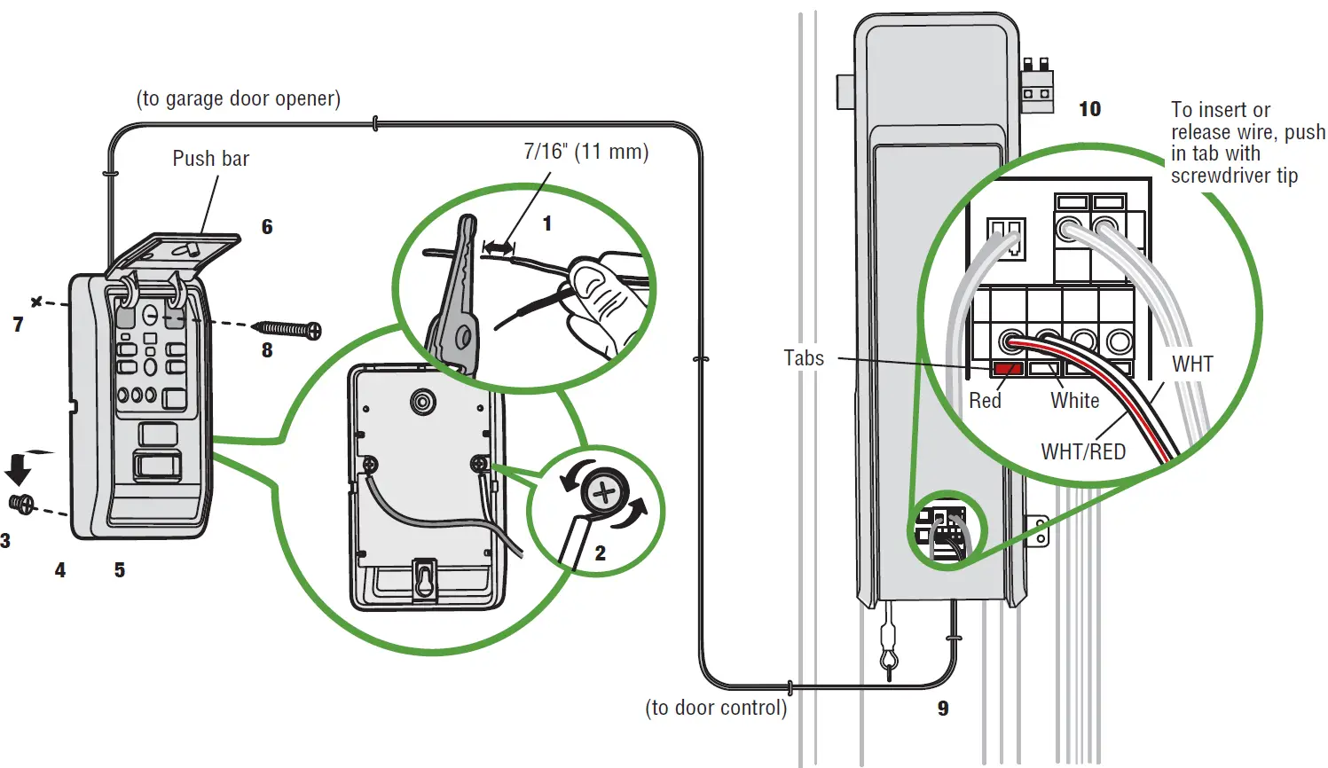
STEP 7: INSTALL THE DOOR CONTROL (MOTION DETECTING CONTROL PANEL)
Install door control within sight of garage door, out of reach of small children at a minimum height of 5 feet (1.5 m) above floors, landings, steps or any other adjacent walking surface, and away from ALL moving parts of door.Install the entrapment warning placard next to the door control in a prominent location.
WARNINGTo prevent possible SERIOUS INJURY or DEATH from electrocution:
- Be sure power is NOT connected BEFORE installing door control.
- Connect ONLY to 7-28 VOLT low voltage wires.
To prevent possible SERIOUS INJURY or DEATH from a closing garage door:
- Install door control within sight of garage door, out of reach of small children at a minimum height of 5 feet (1.5 m) above floors, landings, steps or any other adjacent walking surface, and away from ALL moving parts of door.
- NEVER permit children to operate or play with door control push buttons or remote control transmitters.
- Activate door ONLY when it can be seen clearly, is properly adjusted, and there are no obstructions to door travel.
- ALWAYS keep garage door in sight until completely closed. NEVER permit anyone to cross path of closing garage door.
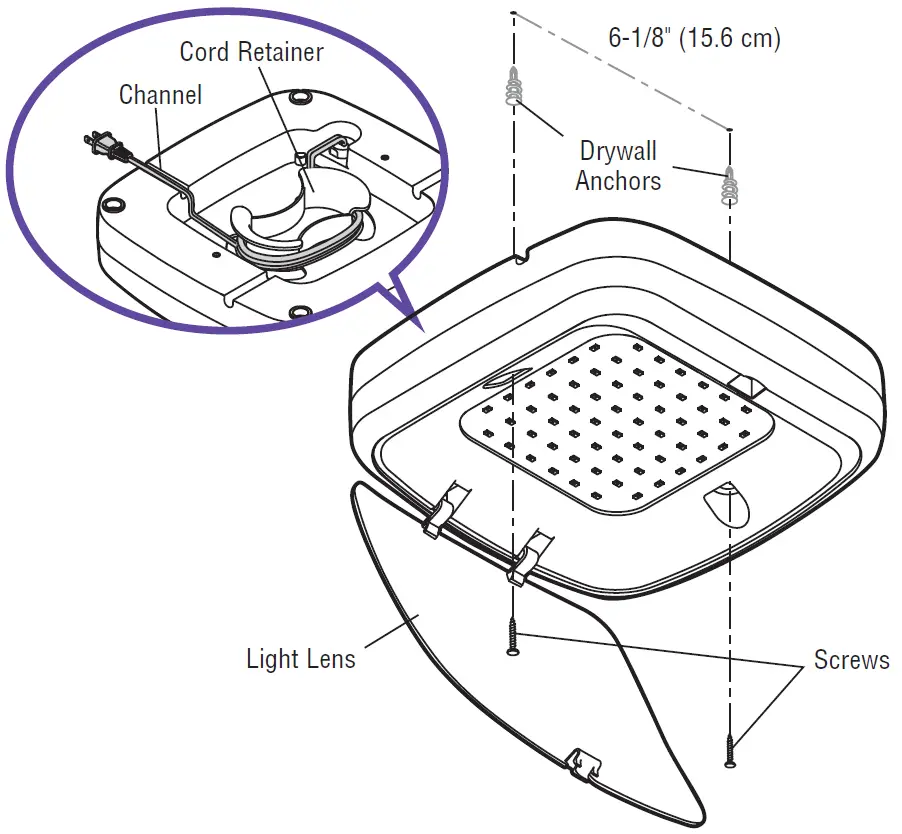
STEP 8: INSTALL REMOTE LIGHTThe Smart LED Light is designed to plug into a standard outlet.Before drilling, place the light against the ceiling. Use a pencil to mark the locations of the screws.Open the light lens and use the screws to mount the light to the ceiling within 6 ft (1.83m) of the outlet, keeping the cord and light away from any moving parts. Once installed, close the light lens and plug the light into the outlet.NOTE: The LED light is very bright. DO NOT stare at the light while on a ladder.Your garage door opener remote light has already been programmed at the factory to operate with your opener. Any additional or replacement remote lights will need to be programmed.
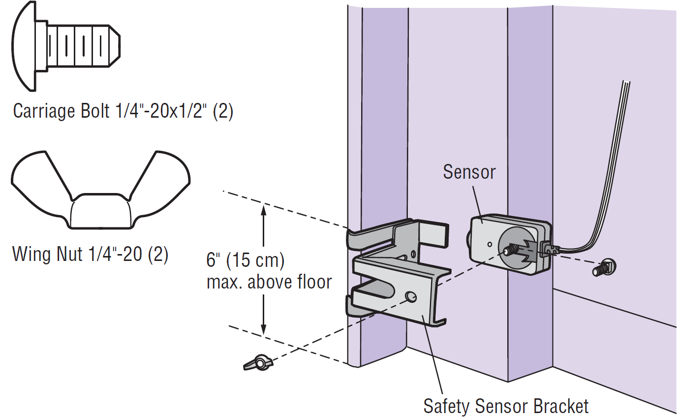
STEP 9: INSTALL THE PROTECTOR SYSTEM®The safety reversing sensors must be connected and aligned correctly before the garage door will move in the down direction. This is a required safety device and cannot be disabled.
- Install and align the brackets so the safety reversing sensors will face each other across the garage door, with the beam no higher than 6″ (15 cm) above the floor.
- Wire to the garage door opener, see CONNECT POWER.
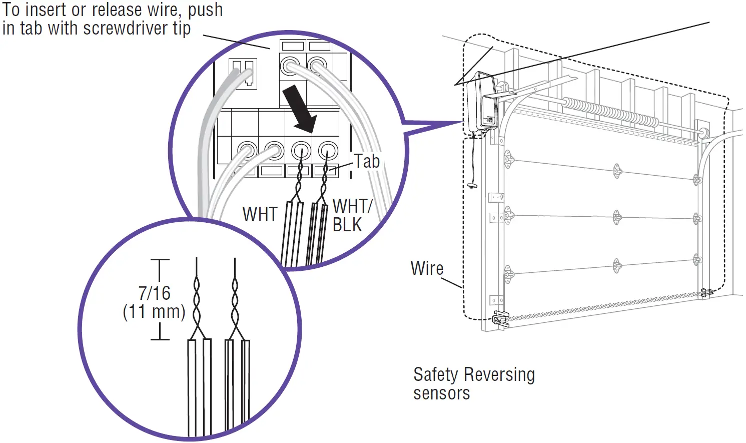
- Strip 7/16″ (11 mm) of insulation from each set of wires. Separate the wires. Twist the white wires together, then the white/black wires together.
NOTE: See Owners Manual for Floor Installation of the Protector System
WIRE THE SAFETY REVERSING SENSORSRun the wire from both sensors to the garage door opener. Securely affix the wire to the wall and ceiling with staples.Strip 7/16 inch (11 mm) of insulation from each set of wires. Separate white from the black the wires. Twist the white wires together, then the white/black wires together. On the garage door opener, push the tab with a screwdriver tip to insert the white wires into the white terminal and the white/black wires into the grey terminal.
STEP 10: CONNECT POWERTo avoid installation difficulties, do not run the garage door opener at this time.To reduce the risk of electric shock, your garage door opener has a grounding type plug with a third grounding pin. This plug will only fit into a grounding type outlet. If the plug doesn’t fit into the outlet you have, contact a qualified electrician to install the proper outlet.There are two options for connecting power:OPTION A: TYPICAL WIRING
- Plug in the garage door opener into a grounded outlet.
- DO NOT run garage door opener at this time.
OPTION B: PERMANENT WIRINGSee your Owner’s Manual for permanent wiring option.
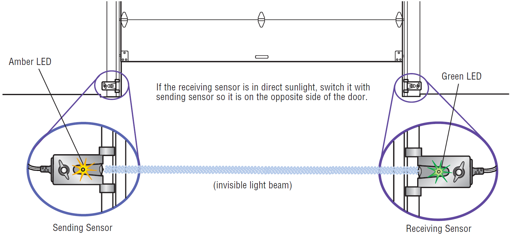
ALIGN THE SAFETY REVERSING SENSORSThe door will not close if the sensors have not been installed and aligned correctly.The LEDs in both sensors must be glowing steady which indicates they are powered and aligned correctly. The sending sensor (with an amber LED) transmits an invisible light beam to the receiving sensor (with a green LED). If an obstruction breaks the light beam while the door is closing, the door will stop and reverse to the full open position, and the remote lights will flash 10 times. If the door is already open, it will not close.
TO ALIGN SENSORS:The sensors can be aligned by loosening the wing nuts, aligning the sensors, and tightening the wing nuts.
If the LEDs are not glowing steadily:
- Check that both sensors are installed inside the garage, one on either side of the door.
- Check that sensors are facing each other with the lenses aligned and the receiving sensor light does not receive direct sunlight.
- Check that sensors have the same measurement, no higher than 6” above the floor.Amber LED is not lit:
- Check there is power to the garage door opener.
- Check the sensor wire is not shorted/broken.
- Check the sensor has been wired correctly: white wires to white terminal and white/black wires to grey terminal.
Green LED is not lit:
- Check that the sensor wire is not shorted/broken.
- Check that the sensors are aligned.
ENSURE THE DOOR CONTROL IS WIRED CORRECTLYThe yellow Command LED and the red Learn LED on the door control will blink quickly for up to 5 minutes as the door control recharges. When the door control is operational, the yellow Command LED will glow steadily
FINISHING STEPS
IMPORTANT SAFETY INSTRUCTIONS
- READ AND FOLLOW ALL WARNINGS AND INSTRUCTIONS.
- ALWAYS keep remote controls out of reach of children. NEVER permit children to operate or play with door control push buttons or remote controls.
- ONLY activate door when it can be seen clearly, it is properly adjusted and there are no obstructions to door travel.
- ALWAYS keep garage door in sight and away from people and objects until completely closed. NO ONE SHOULD CROSS THE PATH OF THE MOVING DOOR.
- NO ONE SHOULD GO UNDER A STOPPED, PARTIALLY OPENED DOOR.
- If possible, use emergency release handle to disengage door ONLY when door is CLOSED. Use caution when using this release with the door open. Weak or broken springs or unbalanced door could result in an open door falling rapidly and/or unexpectedly and increasing the risk of SEVERE INJURY or DEATH.
- NEVER use emergency release handle unless doorway is clear of persons and obstructions.
- After ANY adjustments are made, the safety reversal system MUST be tested. Failure to adjust the garage door opener properly may cause SEVERE INJURY or DEATH.
- Safety reversal system MUST be tested every month. Door MUST reverse on contact with 1-1/2″ (3.8 cm) high object (or a 2×4 laid flat) on the floor. Failure to adjust the garage door opener properly may cause SEVERE INJURY or DEATH.
- ALWAYS KEEP DOOR PROPERLY BALANCED (see page 4). An improperly balanced door may NOT reverse when required and could result in SEVERE INJURY or DEATH.
- ALL repairs to cables, spring assemblies and other hardware, ALL of which are under EXTREME tension, MUST be made by a trained door systems technician.
- To avoid SERIOUS PERSONAL INJURY or DEATH from electrocution, disconnect ALL electric and battery power BEFORE performing ANY service or maintenance.
- This operator system is equipped with an unattended operation feature. The door could move unexpectedly. NO ONE SHOULD CROSS THE PATH OF THE MOVING DOOR.
- SAVE THESE INSTRUCTIONS.
GETTING CONNECTED
CONNECT WITH YOUR SMARTPHONEThis WiFi® Garage Door Opener is compatible with up to 16 myQ® enabled accessories that can be controlled using the myQ® app.You will need:
- Wi-Fi® enabled smartphone or tablet
- Broadband Internet Connection
- Wi-Fi® signal in the garage (2.4 Ghz, 802.11b/g/n required)
- Password for your home network (router’s main account, not guest network)
- myQ® serial number located on the garage door opener
SYNCHRONIZE THE DOOR CONTROLTo synchronize the door control to the garage door opener, press the push bar until the garage door opener activates (it may take up to 3 presses). The garage door opener must run through a complete cycle before it will activate Wi-Fi® programming.
DOWNLOAD THE myQ® APP TO SET UP AN ACCOUNT AND CONNECTOpen and close your door, get alerts and set schedules from anywhere. Connected smart garage door openers also receive software updates to ensure the opener has the latest operational features.
- Download the myQ® App.
- Set up an account and connect.
For more information on connecting your garage door opener, visit Chamberlain.com/Customer-Support.
|
LED |
Definition |
|
Blue |
Off – Wi-Fi® is not turned on.
Blinking – Garage door opener is in Wi-Fi® learn mode. Solid – Mobile device connected to the garage door opener. |
|
Blue and Green |
Blinking – Attempting to connect to router. |
|
Green |
Blinking – Attempting to connect to the Internet server. Solid – Wi-Fi® has been set up and garage door opener is connected to the Internet. |
Your hardware is installed, but Installation is not complete.Please see the table below for important steps required to ensure Safe Operation.
|
IMPORTANT |
|
|
REFER TO YOUR OWNER’S MANUAL TO COMPLETE YOUR INSTALLATION |
|
| 1. Program the Travel Limits |
Page 24 |
| 2. Test the Safety Reversal System |
Page 25 |
| 3. Test the Protector System |
Page 25 |
| 4. Test the Power Door Lock |
Page 26 |
| 5. Test the Cable Tension Monitor |
Page 26 |
| 6. Test the Emergency Release |
Page 26 |
| 7. Programming Additional Accessories |
Page 31 |
![]()
[xyz-ips snippet=”download-snippet”]