CHAMP HBZ4900 Games Airplane Instruction Manual
NOTICE
All instructions, warranties and other collateral documents are subject to change at the sole discretion of Horizon Hobby, Inc. For up-to-date product literature, visit www.horizonhobby.com and click on the support tab for this product.
Meaning of Special Language:
The following terms are used throughout the product literature to indicate various levels of potential harm when operating this product:NOTICE: Procedures, which if not properly followed, create a possibility of physical property damage AND little or no possibility of injury.CAUTION: Procedures, which if not properly followed, create the probability of physical property damage AND a possibility of serious injury.WARNING: Procedures, which if not properly followed, create the probability of property damage, collateral damage, and serious injury OR create a high probability of superficial injury.
Age Recommendation: Not for children under 14 years. This is not a toy.
![]() WARNING: Read the ENTIRE instruction manual to become familiar with the features of the product before operating. Failure to operate the product correctly can result in damage to the product, personal property and cause serious injury. This is a sophisticated hobby product. It must be operated with caution and common sense and requires some basic mechanical ability. Failure to operate this Product in a safe and responsible manner could result in injury or damage to the product or other property. This product is not intended for use by children without direct adult supervision. Do not attempt disassembly, use with incompatible components or augment product in any way without the approval of Horizon Hobby, Inc. This manual contains instructions for safety, operation and maintenance. It is essential to read and follow all the instructions and warnings in the manual, prior to assembly, setup or use, in order to operate correctly and avoid damage or serious injury.
WARNING: Read the ENTIRE instruction manual to become familiar with the features of the product before operating. Failure to operate the product correctly can result in damage to the product, personal property and cause serious injury. This is a sophisticated hobby product. It must be operated with caution and common sense and requires some basic mechanical ability. Failure to operate this Product in a safe and responsible manner could result in injury or damage to the product or other property. This product is not intended for use by children without direct adult supervision. Do not attempt disassembly, use with incompatible components or augment product in any way without the approval of Horizon Hobby, Inc. This manual contains instructions for safety, operation and maintenance. It is essential to read and follow all the instructions and warnings in the manual, prior to assembly, setup or use, in order to operate correctly and avoid damage or serious injury.
Introduction
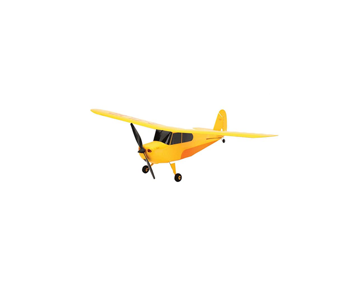
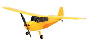
Congratulations on your purchase of the HobbyZone® Champ. The Champ is a fully proportional 3-channel aircraft utilizing throttle, rudder, and elevator controls. You will need to thoroughly read the instruction manual, then charge the flight battery prior to your first flight. For assistance in setting up, charging, flying or troubleshooting your Champ, please contact the appropriate Horizon Product Support office.
Specifications
Wingspan: . . . . . . . . . . 22.4 in (568.9mm)Length:. . . . . . . . . . . . . 14.3 in (365mm)Weight:. . . . . . . . . . . . . 1.3 oz (38 g)
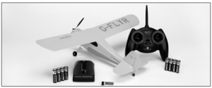
Champ RTF Contents
- Champ RTF airplane
- 2.4GHz DSM2®/DSMX® transmitter
- 150mAh 1S 3.7V Li-Po battery
- 1S 3.7V Li-Po battery charger, 0.3A charge rate
- 8x AA batteries
Safety Precautions and Warnings
As the user of this product, you are solely responsible for operating in a manner that does not endanger yourself and others or result in damage to the product or the property of others.
- Always keep a safe distance in all directions around your model to avoid collisions or This model is controlled by a radio signal subject to interference from many sources outside your control. Interference can cause momentary loss of control
- Always operate your model in open spaces away from full-size vehicles, traffic and
- Always carefully follow the directions and warnings for this and any optional support equipment (chargers, rechargeable battery packs, ).
- Always keep all chemicals, small parts and anything electrical out of the reach of
- Always avoid water exposure to all equipment not specifically designed and protected for this Moisture causes damage to electronics.
- Never place any portion of the model in your mouth as it could cause serious injury or even
- Never operate your model with low transmitter
- Always keep aircraft in sight and under
- Always use fully charged
- Always keep transmitter powered on while aircraft is
- Always remove batteries before
- Always keep moving parts
- Always keep parts
- Always let parts cool after use before
- Always remove batteries after
- Always ensure failsafe is properly set before
- Never operate aircraft with damaged
- Never touch moving
Charging Warnings
While the 1S 3.7V DC Lithium Polymer Battery Charger (EFLB1501S25) included with your Champ has been specifically designed to safely charge the included 1S 3.7V 150mAh Li-Po Battery (PKZ3240), you MUST read the following safety instructions and warnings before handling, charging or using the Li-Po battery.
- By handling, charging or using the included Li-Po battery, you assume all risks associated with lithium
- If at any time the battery begins to balloon or swell, discontinue use If charging or discharging, discontinue and disconnect. Continuing to use, charge or discharge a battery that is ballooning or swelling can result in fire.
- Always store the battery at room temperature in a dry area for best
- Always transport or temporarily store the battery in a temperature range of 40–120º F (5–49º C). Do not store battery or aircraft in a car or direct If stored in a hot car, the battery can be damaged or even catch fi re.
- Always charge batteries away from flammable
- Always inspect the battery before charging and never charge damaged batteries
- Always disconnect the battery after charging, and let the charger cool between charges
- Always constantly monitor the temperature of the battery pack while charging
- ONLY USE A CHARGER SPECIFICALLY DESIGNED TO CHARGE LI-PO Failure to charge the battery with a compatible charger may cause fire resulting in personal injury and/or property damage
- Never discharge Li-Po cells to below 3V under load
- Never cover warning labels with hook and loop strips
- Never leave charging batteries unattached
- Never charge batteries outside recommended levels
- Never attempt to dismantle or alter the charger.
- Never allow minors to charge battery packs.
- Never charge batteries in extremely hot or cold places (recommended between 40–120° F or 5–49° C) or place in direct sunlight.
Li-Po cells should not be discharged to below 3V each underload. In the case of the Li-Po battery used for the Champ, you will not want to allow the battery to fall below 3V during flight. The Champ receiver unit features a soft low voltage cutoff (LVC) that occurs when the battery reaches 3V under load. When the soft cutoff occurs, the ESCs of the receiver unit reduce power to the motor (regardless of the power level set with the throttle stick) in order to prevent the voltage of the battery from dropping below 3V. This power reduction usually requires you to land the model immediately, at which point you should power down the model and unplug the flight battery. While it is possible to power the model up and to fly again after the soft LVC occurs, this is NOT recommended as this will over-discharge the battery. Continued discharging to the soft LVC will cause permanent damage to the Li-Po battery resulting in lost power and duration during subsequent flights, or failure of the battery entirely.Continued attempts to further discharge the battery may also result in loss of control while the motor is running, as the voltage may drop below the minimum operating voltage of the receiver and the other electronics. Also, you should not fly to the soft LVC every time you fly. Instead, you should be aware of the power level of the battery/airplane throughout the flight, and if at any time the airplane begins to require more throttle than typical to maintain flight, you should land the airplane immediately. Routinely discharging the battery to the soft LVC can still cause permanent damage to the battery.
Note: Battery performance can suffer greatly in cooler temperatures. It is recommended the batteries be warm before flight.
First Flight Preparation
Please note this checklist is not intended to be a replacement for the content included in this manual. Although it can be used as a quick start guide, we strongly suggest reading through this manual completely before proceeding
- Remove and inspect contents
- Install 4 AA batteries into the battery charger
- Begin charging the flight battery
- Install batteries in the transmitter (as required)
- Test the controls
- Familiarize yourself with the controls
- Find a suitable area for flying
Battery Charging
See the Battery Warning and Guidelines section and familiarize yourself thoroughly with it before continuing. Follow these steps to charge the Li-Po battery with the included charger. Remove the cover on the bottom of the charger and install four of the included AA batteries, noting proper polarity. Replace the cover after the AA batteries are installed. Slide the battery into the slot on the charger. The end cap of the battery is specifically designed to allow the battery to be slid into the slot easily one way (usually with the label on the battery facing outward) to prevent reverse polarity connection. However, check for proper alignment and polarity before proceeding to the next step. Gently press the battery and its connector into the charge jack/connector located at the bottom of the slot in the charger.
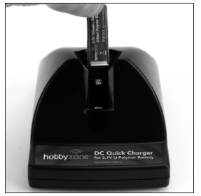
Note: The hook and loop on the battery will cause it to be tight in the battery slot of the charger. When you make the connection successfully, the LED light on the charger turns solid red, indicating charging has begun. Charging a fully discharged (not over-discharged) 150mAh battery takes approximately 30–40 minutes. As the battery nears full charge, the LED light begins to blink. When the battery is fully charged, the LED light blinks approximately every 20 seconds or goes out entirelyNote: The Li-Po battery included with your Champ arrives partially charged, so the initial charge may only take 15–20 minutesNote: You can expect to charge the Li-Po flight battery approximately 10–15 times before needing to replace the AA batteries in the charger. Replacing the included batteries with alkaline batteries results in more charge cycles than with the included batteries.Note: If the LED remains on for longer than 40 minutes while charging and/or 5 seconds after removing the Li-Po flight battery, replace the AA batteries in the charger.
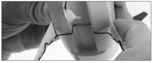
Removing and Installing the Landing Gear
To remove the landing gear, squeeze the wheels together and gently pull the landing gear out of the fuselage. To install the landing gear, squeeze the wheels together and slide the landing gear wire into the slot located on the bottom of the fuselage.
Installing the Flight Battery
After fully charging the battery, install it in the airplane by placing it into the slot on the bottom of the fuselage with the plug facing toward the front of the airplane.Note: If you are using additional batteries without hook and loop tape, we have included extra hook and loop tape pieces to allow you to use these batteries.

Transmitter Control Identification


Control Test
You must test the controls prior to the first flight to ensure none of the servos, linkages or parts were damaged during shipping and handling and the controls function in the correct directions. Turn the transmitter on first and lower the throttle stick completely. Then, plug the battery into the battery lead of the receiver unit.Note: The connectors on the battery and battery lead are keyed to prevent reverse polarity connection. However, if you force them together in the wrong orientation and with the wrong polarity, it is still possible to damage the battery and/or receiver unit. To help further prevent a reverse polarity connection, one side of the end cap on the battery and the connector on the battery lead of the receiver unit have a red dot. The connectors are oriented for a proper polarity connection when the red dots are on the same side.
Move the elevator stick on the transmitter forward and backward to check elevator pitch control. When the stick is pushed forward, the elevator should move down. This will cause the nose of the airplane to drop in flight.
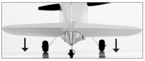
When the elevator stick is moved backward, the elevator should move up. This will cause the nose of the ariplane to lift in flight.

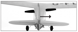
Move the rudder stick left and right to check turn control. When the stick is pushed to the right, the rudder should also move to the right.
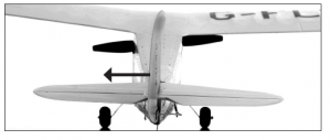
With the rudder stick pushed to the left, the rudder should move to the left.
If at any time during the test the controls respond in the opposite direction, reverse/change the direction of operation of the flight controls. To do this, consult the Reversing Flight Controls section.After reconfirming the flight control directions, all controls should function properly.
Digital Trims
The HobbyZone 2.4GHz DSM2/DSMX transmitter features digital trim buttons next to the control sticks to make fine adjustments. Use these to center the control surfaces. If there is not enough digital trim available, mechanically adjust the loops in the control linkages to center the surfaces. Transmitter Binding Instructions
In the event you need to re-bind your transmitter to your airplane, follow the steps below.
- Plug battery into airplane with the transmitter turned off.
- When you see the LED on the receiver begin to flash while looking through the opening at the back of the battery cavity of the Champ, push the left stick of the transmitter inward into the case (NOT pulling down on throttle stick) until you hear it click.
- While pushing the stick in, power on the transmitter, release stick once the transmitter is powered on. The transmitter will beep and the LED on the face of the transmitter will pulse.
- Once the transmitter stops beeping it will take a second or two to connect with the airplane.
Note: It can be difficult at times to see the LED blink (indicating you are in bind mode), therefore slowly count to five once you have connected the battery and the airplane should enter bind mode at that time.
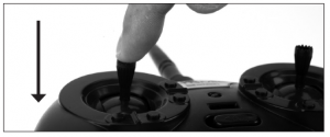
Transmitter Dual Rate Function
The included 2.4GHz DSM2/DSMX transmitter features dual rate capability. The default setting is high rate. To access the low-rate function, press IN on the right stick. The LED light on the transmitter face will blink, alerting you the transmitter is on low rate. To return to high rate, push in again on the right stick.
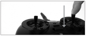
Note: Hobby Zone STRONGLY recommends using the LOW-RATE setting for conducting first flights.
Receiver Control Unit Description, Arming and Motor Control Test
The receiver installed on your Champ is a lightweight combination of main motor electronic speed control, servos and Spektrum DSM2/DSMX-compatible receiver. The receiver unit is also equipped with a status indicator LED
Before each flight ALWAYS turn the transmitter on before connecting the flight battery to the receiver unit. Never connect the flight battery to the receiver unit before powering the transmitter on first. After each flight, always disconnect the flight battery from the receiver unit before powering the transmitter off.
NOTICE: The only time you should connect the flight battery to the receiver unit before powering the transmitter on is when binding the receiver of the receiver unit to the transmitter. Please see the Transmitter and Receiver Binding section for more information
The following checklist contains the steps to properly arm and operate the receiver unit, and check proper motor response.
- You MUST set the throttle stick in the lowest possible position, and, for most transmitters, the throttle trim must also be set to the lowest possible position in order for the receiver unit to If this is the first test flight, or a test flight following repairs, you should also center the rudder, aileron and elevator trims.
- When the status LED on the receiver becomes solid red, the receiver unit is initialized and ready for Also, as long as you had the throttle stick in the idle position and the throttle trim in the lowest position during the initialization process, the ESC/motor will now be armed. Use caution as the propeller will now spin with throttle stick input.
Note: If the status LED of the receiver does not become solid red, please review the following.
- If after blinking red the status LED becomes solid red, but you have no control of the motor, you have a positive Radio Frequency (RF) link between the transmitter and receiver, but the throttle stick and throttle trim may not be set to the correct Check that the throttle stick is in the lowest possible position, and the throttle trim is set to the middle or a lower-than- the-middle position. If you now have control of the motor, proceed to the next step of the checklist. If the blinking red status LED keeps flashing, you do not have a positive RF link between the transmitter and receiver. Ensure the transmitter has been powered on and the LED indicator on the transmitter glows solid red. If the transmitter is powered on and functioning properly, disconnect the flight battery from the receiver unit, then reconnect it. Now the receiver unit should initialize and arm properly.Note: In the event you inadvertently enter Bind Mode, the LED on the receiver flashes red continuously. If this occurs, cycle the flight battery while the transmitter is on (if previously bound). Once you have placed the airplane in a safe area, free of obstructions, and are clear of the propeller, you can safely power up the model to check for proper operation of the motor.
- Advance the throttle stick upward slowly, just until the propeller begins to spin. DO NOT attempt to fly the airplane at this time. Note the direction the propeller spins. If viewed from the front of the airplane, the propeller spins counterclockwise. If it is spinning backwards, disconnect the battery and breverse the polarity of the motor’s input power leads.
Reversing Flight Controls
The transmitter included with the RTF Champ functions identically to the transmitter included with the PKZ Vapor, Ultra-Micro P-51 RTF, Ultra-Micro Cub, E-flite Blade® mCX, Tandem Rescue, and mSR (MLP4DSM). Should the Champ’s electronic components be used in another aircraft, you might need to reverse the operation of flight control surfaces. Follow the steps below to reverse the rudder and elevator operation.
- Be certain the battery is unplugged from the aircraft and the transmitter is turned off.
- Push down on the digital trim button for the surface you would like to reverse.a. Top elevator trim button—elevator normalb. Bottom elevator trim button—elevator reversec. Left rudder trim button—rudder normald. Right rudder trim button—rudder reverse
- Continue holding the desired digital trim button down and turn the transmitter on.
- Hold the digital trim buttons down for about five seconds until hearing tones, which confirm the selection.
- Connect the flight battery. Complete the flight control test, confirming that all surfaces operate in the correct direction.
Stock Control Throw
Out of the box, your Champ should have the approximate control throws. In production, this can vary by approximately 2mm without any effect on flight performance.
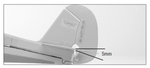
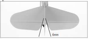
| High Rate | Low Rate | |
| Elevator | 5mm up/down | 3mm up/down |
| Rudder | 6mm left/right | 4mm left/right |
With the battery installed, the center of gravity is approximately 28mm as measured back from the leading edge of the wing. This can vary by approximately 1 to 2mm.
Flying Checklist
- Always turn on the transmitter first
- Plug the flight battery into the lead from the receiver
- Allow the receiver to initialize and arm properly
- M ake sure all control surfaces are responding correctly to transmitter input
- Ensure propeller is secure and not damaged
- Fly the model
- Land the model
- Unplug the flight battery from the receiver
- Always turn off the transmitter last
Choosing a Flying Area
When ready for your first flight, select a relatively open area, the size of a basketball court or larger, that is free of people and obstructions with calm wind (if flown outdoors). Once you have properly trimmed your airplane and become familiar with its handling and capabilities, you will be able to fly in other smaller, less open areas. Larger open areas are preferred for first flights.
Flying the Champ
Use the low-rate settings for your first flight to become familiar with the flying characteristics before increasing the throw of the control surfaces. Place the Champ in position for takeoff (facing into the wind if flying outdoors). Gradually increase the throttle to ½ to ¾ and steer with the rudder. Once the Champ reaches flying speed it lifts off on its own. The Champ climbs with ¾ to full throttle, and roughly ½ throttle allows the Champ to fly without climbing or descending.Note: If at any time you become disoriented or get in trouble, pull the power all the way off and release the controls. The Champ will stabilize into a steady gliding descent.
1. After launching, your Champ will climb at full throttle. Keep the throttle ¾ to full on until reaching a safe altitude. At this same time, make sure you are keeping the airplane steady, directed on its intended path.2. Make necessary right and left adjustments to keep the plane on course. After reaching 4–6 feet of altitude, you can make the directional changes you desire.3. Remember—the Champ is a small, lightweight aircraft. Do not allow the plane to get too far away from you. When the plane is farther away from you it is harder to see and could cause you to lose orientation.4. Avoid holding the stick full right or left for more than two seconds. This will cause the plane to enter a spiral and could threaten your Champ.5. Do not try to climb too fast by pulling all the way back on the stick (up elevator), or your plane may enter into a stall. Instead, climb by giving small amounts of elevator or by increasing throttle.6. Damage/bends to the wings or tail can greatly affect flight control. Repair or replace damaged parts immediately.
In order to make a sharper turn, move the stick in the desired direction and add some up elevator (pull back on the stick). The plane will make a sharper banking turn.Note: With the throttle set at low or off (gliding), the plane will not turn as fast as when you are flying at or near full throttle.
Rudder Trim
If the model wants to constantly turn one direction, use the digital trim buttons to correct. Your Champ should fly straight with the control stick at neutral. Always make trim changes in one-click intervals.
Throttle Adjustment
1. Climb to an altitude of 6–12 feet with full throttle.2. To achieve and maintain a level “cruising” altitude, reduce the power by moving the throttle stick down to approximately 50%. The throttle stick is proportional, so you can add or reduce throttle in small increments as needed to maintain altitude.3. To reduce altitude, reduce throttle.4. To increase altitude, increase throttle.
Using Elevator
Your Champ is equipped with a third channel for elevator (pitch control). Pulling back on the stick provides up elevator. This allows for shorter takeoffs, better flares for landing, better climb rates and more effective turns. Pulling back too far on the elevator, however, causes the airplane to enter a stall, causing the nose of the airplane to drop. To avoid crashing from a stall, always maintain enough altitude to recover.Just after a stall, the nose of the airplane falls and the plane looks like it is diving. To pull out of a stall, pull back slowly on the elevator stick once your Champ has built up airspeed. Remember, pulling back too quickly or for too long will cause the airplane to re-enter a stall. Effectively avoiding and recovering from stalls requires experience. Always seek the help of an experienced radio control pilot if you are not familiar with pitch control. Failure to do so could result in a crash and significant damage to your airplane.
Elevator Trim
If the Champ tends to go up or down, use the elevator digital trim buttons next to the control stick to correct. The model should fly straight with the control stick at neutral and should have a steady climb at full throttle.
Landing Your Champ
When you notice your Champ no longer climbs well under full power (normally after approximately 6–9 minutes), the battery is getting low and it is time to land. Bring in your aircraft toward the desired landing spot. If flying outside, bring the airplane directly into the light wind. Gradually reduce throttle to reach an altitude of approximately 4 feet. At this point, reduce even more throttle and your Champ should glide in softly for a landing.
Auto Cutoff
When the battery gets low enough, this feature automatically shuts off the motor and saves enough battery power to maintain control of the tail so you can land correctly and safely. If the motor cuts off, prepare to land immediately. If you are gliding down and have some time to rest the battery, you may re-arm the motor by moving the throttle slider back to off then advancing it again. This only allows the motor to run briefly, and may allow you to better adjust your landing. Do not re-arm the motor more than once.
Note: Your Champ should be landed on a smooth surface (such as concrete or wood) so the landing gear can work effectively. Expert Tip: As you get better and more experienced at flying, try adding a bit of “up” elevator just prior to landing to “flare” the plane. With some practice, your landings should become smooth and on target.
CAUTION: Do not attempt to catch the airplane or injury may occur. Remember, there is a spinning propeller on the front of the plane that can cause injury! Also, remember to cut power to the motor right before you land to prevent damage to the propeller.
IN THE UNFORTUNATE EVENT OF A CRASH OR PROPELLER STRIKE, NO MATTER HOW MINOR OR MAJOR, YOU MUST LOWER THE THROTTLE STICK AND TRIM TO THEIR LOWEST POSSIBLE POSITIONS AS QUICKLY AS POSSIBLE TO PREVENT DAMAGE TO THE ESC OF THE RECEIVER UNIT.
Failure to lower the throttle stick and trim to the lowest possible positions in the event of a crash could result in damage to the ESC in the receiver unit, which may require replacement of the receiver unit.
NOTICE: Crash damage is not covered under the warranty.
Replacing the Propeller
You may need to replace the propeller in the event of a crash.
If you have access to hemostats, grip the prop shaft between the spinner and fuselage front and turn propeller counterclockwise to remove propeller. If you don’t have hemostats, continue below.
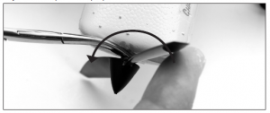
- Have an adult carefully use a hobby knife and cut through the clear tape on the side of the fuselage as well as across the top seem of See Step 1 of Replacing the Prop Shaft.
- Carefully remove fuselage top and side to gain access to the
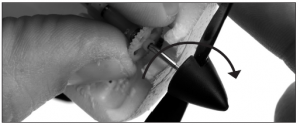
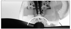
- Grab the spur gear (as shown) and turn propeller counterclockwise until it releases from the prop shaft.
- Thread the new 130mm x 70mm prop and spinner clockwise onto the gearbox shaft.
- Carefully place fuselage parts back and re-tape with clear tape.

Replacing the Prop Shaft
You may need to replace the prop shaft in the gearbox should it become damaged. To replace the prop shaft:
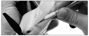
- To remove prop shaft, open the fuselage by cutting through the clear tape on one side of the fuselage. Also cut the tape across the fuselage in front of the rudder.
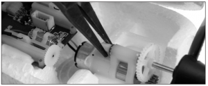
- Gently grasp the white nylon nut located at the back of the prop shaft to prevent it from turning.
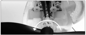
- While holding the nylon nut, rotate the spur gear in a clockwise direction. The prop shaft will thread out of the nut.
- Gently pull on the spur gear and the prop shaft will slide out of the gearbox. You may need to cut away a small portion of foam to allow the spur gear to slide forward out of the gearbox.
- Remove the propeller from the old prop shaft, then thread the 130mm x 70mm prop and spinner on to the new prop shaft by holding the spur gear and turning the prop clockwise.
- Slide the new prop shaft back into the gearbox.
- Place the nylon nut on the back of the prop shaft. Make sure the small brass washer is between the nylon nut and the gearbox. Spin the prop and spur gear counterclockwise. The nylon nut will thread onto the prop shaft.
- While holding the nylon nut in place, gently turn the spur gear counterclockwise to ensure the nut is snug. Make sure not to over-tighten as this will cause binding in the gearbox and reduce performance.
- Tape the fuselage back together with clear tape.
Replacement Parts
HBZ4904. . . . . . . . . . . Prop ShaftHBZ4913. . . . . . . . . . . Decal SheetHBZ4918. . . . . . . . . . . Main Landing Gear SetHBZ4920. . . . . . . . . . . Main WingHBZ4921. . . . . . . . . . . Pushrods with AccessoriesHBZ4929. . . . . . . . . . . Gearbox without MotorHBZ4930. . . . . . . . . . . Gearbox with MotorHBZ4931. . . . . . . . . . . Complete TailHBZ4952. . . . . . . . . . . Fuselage with ElectronicsHBZ4967. . . . . . . . . . . Bare FuselageEFLB1501S25. . . . . . . . 150mAh 1S 3.7V Li-Po BatteryEFL9051. . . . . . . . . . . . 130mm x 70mm Prop with Spinner (2)PKZ3341 . . . . . . . . . . . 2.4GHz DSM2/DSMX TransmitterPKZUA3352 . . . . . . . . . Receiver/ESC Board
Optional Parts
EFLA209. . . . . . . . . . . . Foam-Safe CA (medium)EFLA208. . . . . . . . . . . . Foam-Safe ActivatorEFLC1004AC . . . . . . . . Celectra 4-Port Charger with AC Adapter
Troubleshooting Guide
If you have any problems with setup or programming that cannot be fixed by the Troubleshooting Guide, please contact the appropriate Horizon Product Support office.
| Problem | Possible Solutions |
| Aircraft will not “throttle up” but all other controls seem to function. | Lower throttle trim and/or throttle stick to their lowest settings. |
| Propeller or motor shaft is broken. | Replace with Prop with Spinner (EFL9051) or Prop Shaft (HBZ4904). |
| Aircraft appears to show significant decrease in flight time. | Recharge flight battery completely.Replace AA batteries in charger and recharge flight battery completely.Replace EFLB1501S25 battery and read the “Battery Warnings and Guidelines” section of manual. |
| Charger light stays on afterLi-Po battery is disconnected, or remains on for longer than 40 minutes when charging. | Replace AA batteries in charger. |
| Aircraft appears to have less power. | Lubricate the bushings of the gearbox. Lubricate the bushings of the motor.In cold weather, make sure the batteries are warm before flight. |
| LED on aircraft remains flashing and cannot be controlled by transmitter. | Unplug and reconnect flight battery.Rebind the aircraft to the desired compatible transmitter.Move transmitter (powered on) a few feet from the aircraft prior to reconnecting the flight battery. |
| Aircraft appears to roll or pitch towards a certain direction. | Trim control surfaces using the transmitter until the aircraft no longer moves that direction. |
| Controls appear to be reversed after binding to a different transmitter. | Read the “Control Test” section of manual. |
| Aircraft does not function after connecting flight battery and the aircraft smells burnt. | Replace the receiver/ESC board (PKZ3351) and check for correct polarity when connecting the flight battery. |
Limited Warranty
What this Warranty Covers
Horizon Hobby, Inc. (“Horizon”) warrants to the original purchaser that the prod- uct purchased (the “Product”) will be free from defects in materials and work- manship at the date of purchase.
What is Not Covered
This warranty is not transferable and does not cover (i) cosmetic damage, (ii) damage due to acts of God, accident, misuse, abuse, negligence, commercial use, or due to improper use, installation, operation or maintenance, (iii) modifica- tion of or to any part of the Product, (iv) attempted service by anyone other than a Horizon Hobby authorized service center, (v) Product not purchased from an authorized Horizon dealer, or (vi) Product not compliant with applicable technical regulations.
OTHER THAN THE EXPRESS WARRANTY ABOVE, HORIZON MAKES NO OTHER WARRANTY OR REPRESENTATION, AND HEREBY DISCLAIMS ANY AND ALL IMPLIED WARRANTIES, INCLUDING, WITHOUT LIMITATION, THE IMPLIED
WARRANTIES OF NON-INFRINGEMENT, MERCHANTABILITY AND FITNESS FOR A PARTICULAR PURPOSE. THE PURCHASER ACKNOWLEDGES THAT THEY ALONE HAVE DETERMINED THAT THE PRODUCT WILL SUITABLY MEET THE REQUIREMENTS OF THE PURCHASER’S INTENDED USE.
Purchaser’s Remedy
Horizon’s sole obligation and purchaser’s sole and exclusive remedy shall be that Horizon will, at its option, either (i) service, or (ii) replace, any Product deter- mined by Horizon to be defective. Horizon reserves the right to inspect any and all Product(s) involved in a warranty claim. Service or replacement decisions are at the sole discretion of Horizon. Proof of purchase is required for all warranty claims. SERVICE OR REPLACEMENT AS PROVIDED UNDER THIS WARRANTY IS THE PURCHASER’S SOLE AND EXCLUSIVE REMEDY.
Limitation of Liability
HORIZON SHALL NOT BE LIABLE FOR SPECIAL, INDIRECT, INCIDENTAL OR CONSEQUENTIAL DAMAGES, LOSS OF PROFITS OR PRODUCTION OR COMMERCIAL LOSS IN ANY WAY, REGARDLESS OF WHETHER SUCH CLAIM IS BASED IN CONTRACT, WARRANTY, TORT, NEGLIGENCE, STRICT LIABILITY OR ANY OTHER THEORY OF LIABILITY, EVEN IF HORIZON HAS BEEN ADVISED OF THE POSSIBILITY OF SUCH DAMAGES.Further, in no event shall the liability of Horizon exceed the individual price of the Product on which liability is asserted. As Horizon has no control over use, setup, final assembly, modification or misuse, no liability shall be assumed nor accepted for any resulting damage or injury. By the act of use, setup or assembly, the user accepts all resulting liability. If you as the purchaser or user are not prepared to accept the liability associated with the use of the Product, purchaser is advised to return the Product immediately in new and unused condition to the place of purchase.
Law
These terms are governed by Illinois law (without regard to conflict of law princi- pals). This warranty gives you specific legal rights, and you may also have other rights which vary from state to state. Horizon reserves the right to change or modify this warranty at any time without notice.
\WARRANTY SERVICESQuestions, Assistance, and Services
Your local hobby store and/or place of purchase cannot provide warranty support or service. Once assembly, setup or use of the Product has been started, you must contact your local distributor or Horizon directly. This will enable Horizon to better answer your questions and service you in the event that you may need any assistance. For questions or assistance, please visit our website at www.horizon hobby.com, submit a Product Support Inquiry, or call 877.504.0233 toll free to speak to a Product Support representative
Inspection or Services
If this Product needs to be inspected or serviced and is compliant in the country you live and use the Product in, please use the Horizon Online Service Request submission process found on our website or call Horizon to obtain a Return Merchandise Authorization (RMA) number. Pack the Product securely using a shipping carton. Please note that original boxes may be included, but are not designed to withstand the rigors of shipping without additional protection. Ship via a carrier that provides tracking and insurance for lost or damaged parcels, as Horizon is not responsible for merchandise until it arrives and is accepted at our facility. An Online Service Request is available at http://www.horizonhobby. com/content/_service-center_render-service-center. If you do not have internet access, please contact Horizon Product Support to obtain a RMA number along with instructions for submitting your product for service. When calling Horizon, you will be asked to provide your complete name, street address, email address and phone number where you can be reached during business hours. When sending product into Horizon, please include your RMA number, a list of the
included items, and a brief summary of the problem. A copy of your original sales receipt must be included for warranty consideration. Be sure your name, address, and RMA number are clearly written on the outside of the shipping carton.
NOTICE: Do not ship LiPo batteries to Horizon. If you have any issue with a LiPo battery, please contact the appropriate Horizon Product Support office.
Warranty Requirements
For Warranty consideration, you must include your original sales receipt verifying the proof-of-purchase date. Provided warranty conditions have been met, your Product will be serviced or replaced free of charge. Service or replacement decisions are at the sole discretion of Horizon.
Non-Warranty Service
Should your service not be covered by warranty, service will be com- pleted and payment will be required without notification or estimate of the expense unless the expense exceeds 50% of the retail purchase cost.By submitting the item for service you are agreeing to payment of the service with- out notification. Service estimates are available upon request. You must include this request with your item submitted for service. Non-warranty service estimates will be billed a minimum of ½ hour of labor. In addition you will be billed for return freight. Horizon accepts money orders and cashier’s checks, as well as Visa, MasterCard, American Express, and Discover cards. By submitting any item to Horizon for service, you are agreeing to Horizon’s Terms and Conditions found on our website http://www.horizonhobby.com/content/_service-center_render- service-center.
NOTICE: Horizon service is limited to Product compliant in the country of use and ownership. If non-compliant product is received by Horizon for service, it will be returned unserviced at the sole expense of the purchaser.
| Country of Purchase | Horizon Hobby | Address | Phone Number/Email Address |
|
United States of America |
Horizon Service Center (Electronics and engines) | 4105 Fieldstone Rd Champaign, Illinois 61822 USA | 877-504-0233Online Repair Request: visit www.horizonhobby.com/service |
| Horizon Product Support (All other products) | 4105 Fieldstone Rd Champaign, Illinois 61822 USA | 877-504-0233[email protected] | |
| United Kingdom | Horizon Hobby Limited | Units 1-4 Ployters Rd Staple TyeHarlow, Essex CM18 7NSUnited Kingdom | +44 (0) 1279 641 097[email protected] |
| Germany | Horizon Technischer Service | Christian-Junge-Straße 125337 Elmshorn Germany | +49 (0) 4121 2655 100[email protected] |
| France | Horizon Hobby SAS | 14 Rue Gustave Eiffel Zone d’Activité du Réveil Matin 91230 Montgeron | +33 (0) 1 60 47 44 70[email protected] |
| China | Horizon Hobby – China | Room 506, No. 97 Changshou Rd. Shanghai, China, 200060 | +86 (021) 5180 9868[email protected] |
FCC Statement
This device complies with part 15 of the FCC rules. Operation is subject to the following two conditions:
(1) This device may not cause harmful interference, and(2) this device must accept any interference received, including interference that may cause undesired operation.
Caution: Changes or modifications not expressly approved by the party responsible for compliance could void the user’s authority to operate the equipment. This product contains a radio transmitter with wireless technology which has been tested and found to be compliant with the applicable regulations governing a radio transmitter in the 2.400GHz to 2.4835GHz frequency range
Compliance Information for the European Union
 Declaration of Conformity (in accordance with ISO/IEC 17050-1)No. HH2012071903Product(s): Champ RTFItem Number(s): HBZ4900/HBZ4900I/HBZ4900IM1Equipment class: 1The object of declaration described above is in conformity with the requirements of the specifications listed below, following the provisions of the European R&TTE directive 1999/5/EC, EMC Directive 2004/108/EC and LVD Directive 2006/95/EC:
EN 300-328 V1.7.1EN 301 489-1 V1.7.1: 2006EN 301 489-17 V1.3.2: 2008EN 60950-1:2006+A12: 2011EN55022: 2010EN55024: 2010Signed for and on behalf of:Horizon Hobby, Inc.Champaign, IL USAJuly 19, 2012
Instructions for Disposal of WEEE by Users in the European Union
 Instructions for Disposal of WEEE by Users in the European Union
This product must not be disposed of with other waste. Instead, it is the user’s responsibility to dispose of their waste equipment by handing it over to a designated collection point for the recycling of waste electrical and electronic equipment. The separate collection and recycling of your waste equipment at the time of disposal will help to conserve natural resources and ensure that it is recycled in a manner that protects human health and the environment. For more information about where you can drop off your waste equipment for recycling, please contact your local city office, your household waste disposal service or where you purchased the product.
Read More About This Manual & Download PDF:
References
Ferngesteuerte Flugmodelle, Autos, Trucks, Hubschrauber, Boote und Fernsteuerungen | Horizon Hobby
RC Airplanes and Helicopters, RC Cars and Trucks, RC Boats, RC Radios | Horizon Hobby
RC Airplanes and Helicopters, RC Cars and Trucks, RC Boats, RC Radios | Horizon Hobby
Ferngesteuerte Flugmodelle, Autos, Trucks, Hubschrauber, Boote und Fernsteuerungen | Horizon Hobby
RC Airplanes and Helicopters, RC Cars and Trucks, RC Boats, RC Radios | Horizon Hobby
Service Center Landing Page
hobby.com – This website is for sale! – hobby Resources and Information.
[xyz-ips snippet=”download-snippet”]