
![]()
INSTALLATION MANUALMODEL #40065WHEEL KIT
| REGISTER YOUR PRODUCT ONLINE |
or visit championpowerequipment.com
INTRODUCTION
Congratulations on your purchase of a Champion Power Equipment(CPE) product. CPE designs build and support all of ourproducts to strict specifications and guidelines. With proper product knowledge, safe use, and regular maintenance, this product should bring years of satisfying service.Every effort has been made to ensure the accuracy and completeness of the information in this manual at the time of publication, and we reserve the right to change, alter and/or improve the product and this document at any time without priornotice.CPE highly values how our products are designed, manufactured, operated, and serviced as well as providing safety to the operator and those around the generator. Therefore, it is IMPORTANT to review this product manual and other product materials thoroughly and be fully aware and knowledgeable of the assembly, operation, dangers, and maintenance of the product before use. Fully familiarize yourself, and make sure others who plan on operating the product fully familiarize themselves too, with the proper safety and operating procedures before each use. Please always exercise common sense and always err on the side of caution when operating the product to ensure no accident, property damage, or injury occurs. We want you to continue to use and be satisfied with your CPE product for years to come.When contacting CPE about parts and/or services, you will need to supply the complete model and serial numbers of your product. Transcribe the information found on your product’s nameplate label to the table below
| CPE TECHNICAL SUPPORT TEAM |
| 1-877-338-0999 |
| MODEL NUMBER |
| 40065 |
| SERIAL NUMBER |
| DATE OF PURCHASE |
| PURCHASE LOCATION |
SAFETY DEFINITIONS
The purpose of safety symbols is to attract your attention to possible dangers. The safety symbols, and their explanations, deserve your careful attention and understanding. The safety warnings do not by themselves eliminate any danger. The instructions or warnings they give are not substitutes for proper accident prevention measures.
![]() DANGERDANGER indicates a hazardous situation that, if not avoided, will result in death or serious injury.
DANGERDANGER indicates a hazardous situation that, if not avoided, will result in death or serious injury.
![]() WARNINGWARNING indicates a hazardous situation that, if not avoided, could result in death or serious injury.
WARNINGWARNING indicates a hazardous situation that, if not avoided, could result in death or serious injury.
![]() CAUTIONCAUTION indicates a hazardous situation that, if not avoided, could result in minor or moderate injury.
CAUTIONCAUTION indicates a hazardous situation that, if not avoided, could result in minor or moderate injury.
![]() NOTICENOTICE indicates information considered important, but not hazard-related (e.g., messages relating to property damage).
NOTICENOTICE indicates information considered important, but not hazard-related (e.g., messages relating to property damage).
IMPORTANT SAFETY INSTRUCTIONS
![]() CAUTIONThe wheel kit is not intended for over-the-road use.
CAUTIONThe wheel kit is not intended for over-the-road use.
CONTROLS AND FEATURES
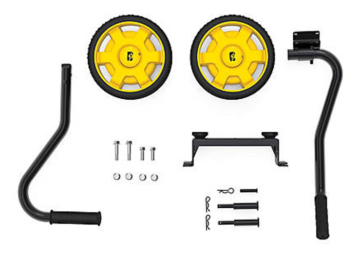
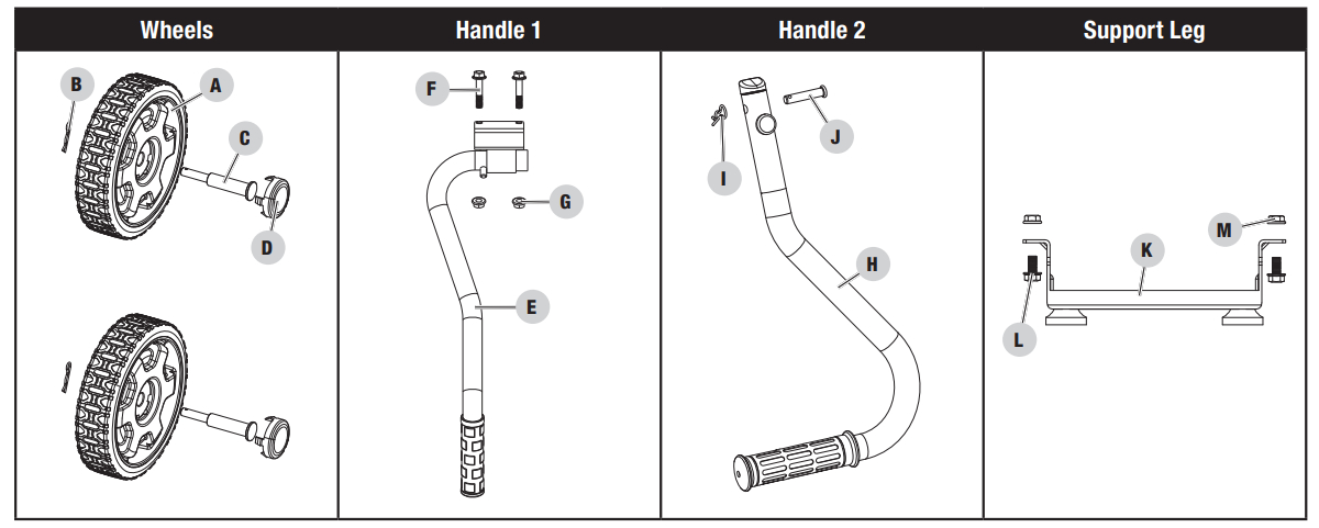
Parts Included
|
Part |
Part Qty. | Hardware | Hardware Qty. |
Tool(s) Needed |
| A. Wheels | 2 | B. Pin Ø2 x 33, “R” Shape | 2 | |
| C. Roll Pin, Wheel, Ø16 x Ø10 x 97 | 2 | |||
| D. Wheel Cap | 2 | |||
| E. Handle 1 | 1 | F. Flange Bolt M8 x 45 | 2 | 1x 12mm wrench |
| G. Lock Nut M8 Flange | 2 | 1x 13mm wrench | ||
| H. Handle 2 | 1 | I. R-pin R5 | 1 | |
| J. Roll Pin Ø8 x 40 | 1 | |||
| K. Support Leg | 1 | L. Flange Bolt M8 x 16 | 2 | 1x 12mm wrench |
| M. Lock Nut M8 Flange | 2 | 1x 13mm wrench |
Tools Not Included– 12mm wrench– 13mm wrench
ASSEMBLY
Your wheel kit requires assembly. For questions regarding the assembly of your wheel kit, call our helpline at 1-877-338-0999. Please have your model number available.
Remove the Wheel Kit and Parts from the Shipping Carton
- Set the shipping carton on a solid, flat surface.
- Remove all contents from the carton.
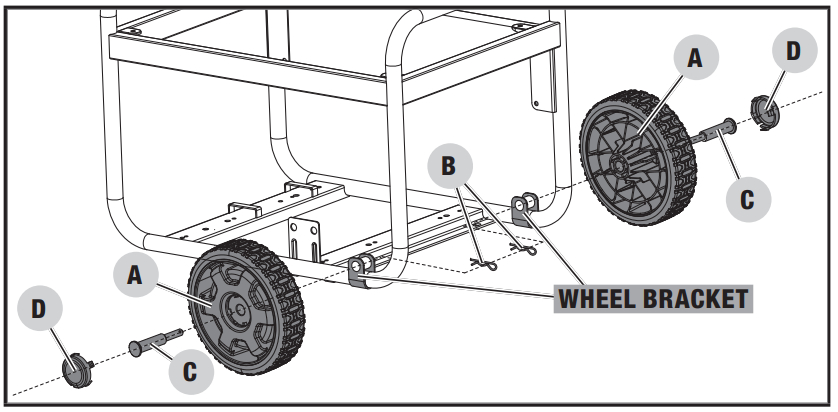
Install Wheels
- Drain oil and fuel, and then tip the generator slowly so that the engine (or panel depending on the exact model) side is this is so you have access to the wheel brackets.
- Remove the wheel cap (D) from the wheel (A) by inserting a small screwdriver into the slot on the cap and pry upward.Remove the cap.
- Slide the roll pin (C) through the wheel (A) from the outside.
- Slide the roll pin through the wheel bracket on the frame.
- Insert R-clip (B) into the hole at end of the roll pin.
- Install wheel cap on the wheel.
- Repeat on the second wheel.
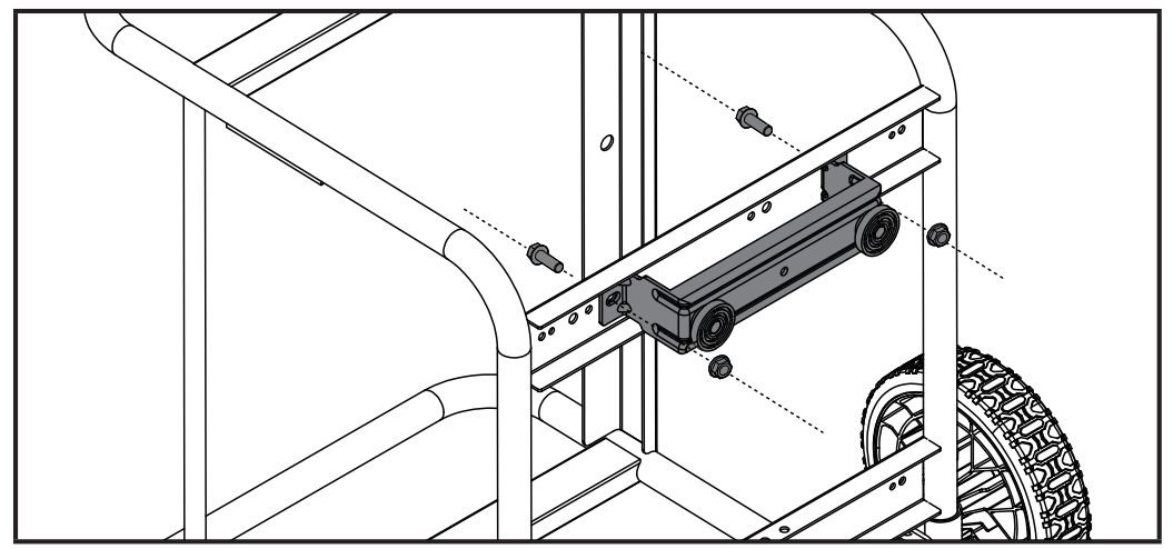
Install the Support Leg
![]() NOTICESome generator models will require removing rubber pads prior to installing the support leg. The support leg will use the same holes as the rubber pads.
NOTICESome generator models will require removing rubber pads prior to installing the support leg. The support leg will use the same holes as the rubber pads.
![]() NOTICESome generators will have the nut or bolt welded to the frame. In this case, secure the support leg to the generator frame with the necessary hardware and recycle the unused hardware according to your local municipalities instructions.
NOTICESome generators will have the nut or bolt welded to the frame. In this case, secure the support leg to the generator frame with the necessary hardware and recycle the unused hardware according to your local municipalities instructions.
- Attach the support leg to the generator frame by sliding the flange bolts M8 x 16 DOWN through the top of the frame and support leg and securing with flange lock nuts from the bottom as shown in the picture below. DO NOT over-tighten the lock nuts. DO NOT slide flange bolts UP through the bottom of the frame.

- Tip the generator slowly so that it rests on the wheels and support leg.
Install the Handle
Please check your generator’s handle bracket to determine which handle type you need. Use the enclosed hardware for assembly. You will only need one or the other handle for your generator.
![]() NOTICEPlease recycle the unused handle according to your local municipalities instructions.
NOTICEPlease recycle the unused handle according to your local municipalities instructions.
Handle 1This handle will bolt to your generator frame. See instructions below.
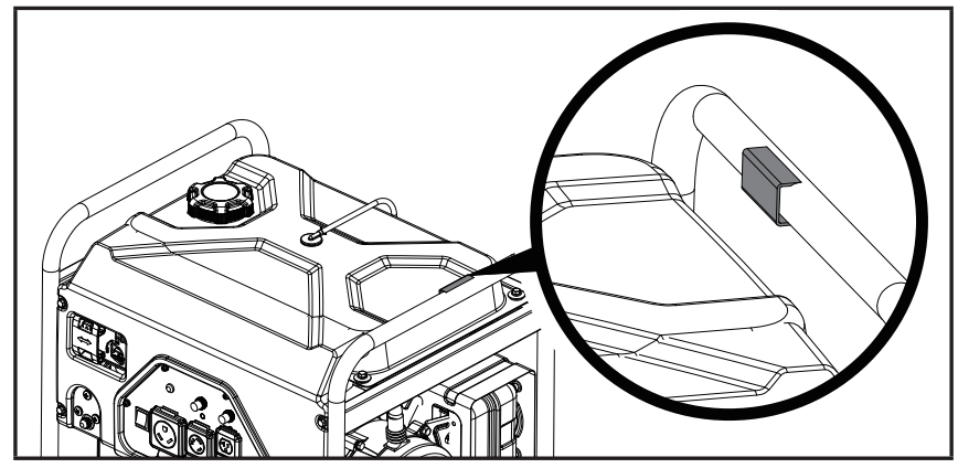
Handle 2This handle uses an R clip and a rolling pin to assemble to your generator frame. See instructions below.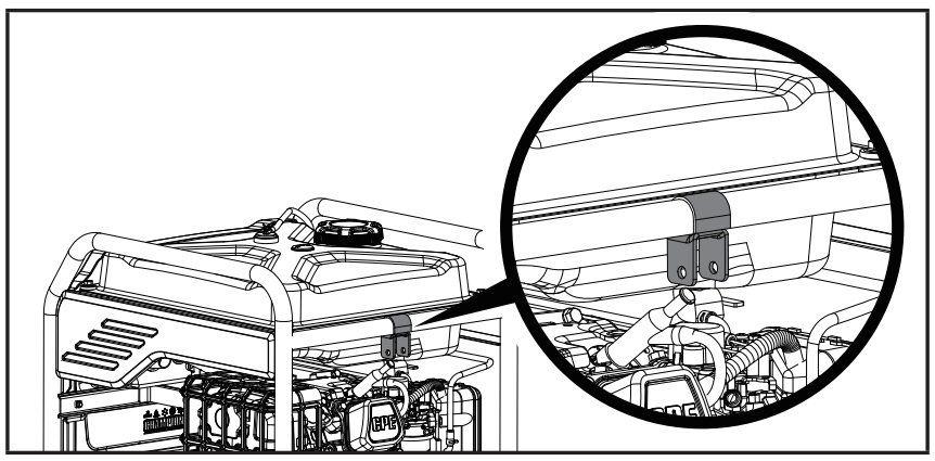
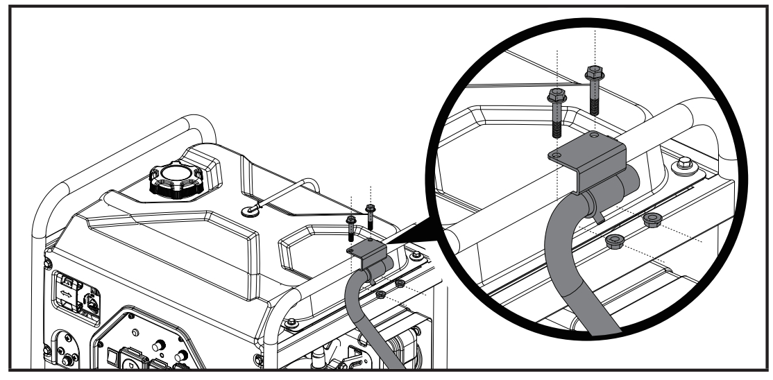
Install the Handle 1
- Place the handle over the mounting channel on the frame.
- Secure the handle to the frame using the two Flange Bolts M8 x 45.
- Place a flange lock nut on the end of each bolt and fasten securely. DO NOT over-tighten the locknuts.
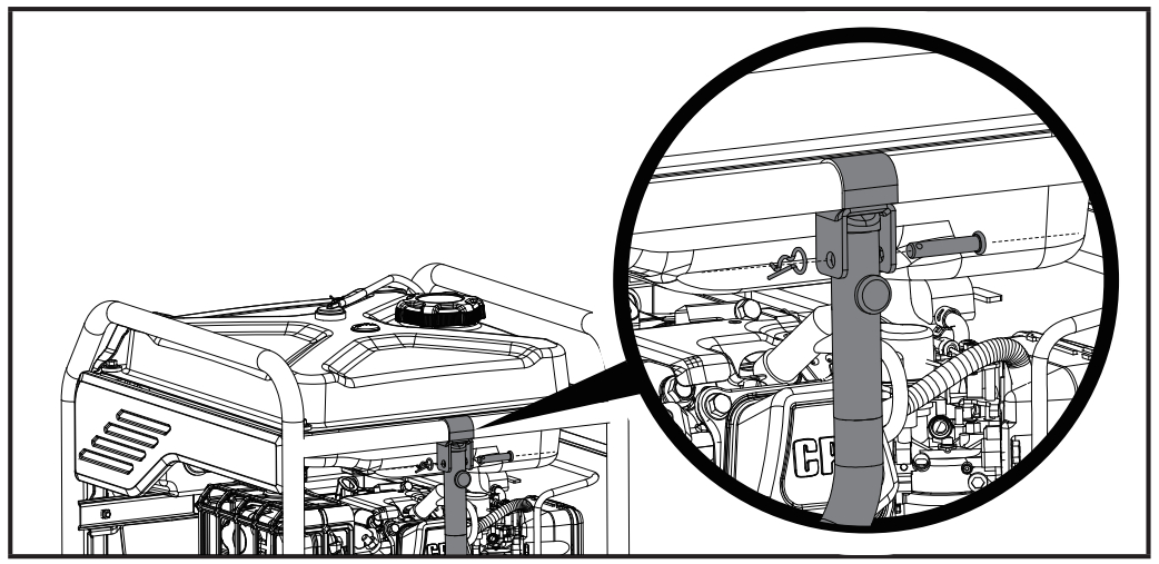
Install the Handle 2
- Place the handle inside the handle mounting bracket with a rubber grip pointing away from the muffler and line up the through-holes of the handle and bracket.
- Secure the handle to the frame by sliding the Roll Pin Ø8 x 40 and locking it into place by pushing the R-clip through the Roll Pinhole.
![]() CAUTIONDO NOT attempt to crank or start the engine before it has been properly filled with the recommended type and amount of oil. Damage to the generator as a result of failing to follow these instructions will void your warranty.
CAUTIONDO NOT attempt to crank or start the engine before it has been properly filled with the recommended type and amount of oil. Damage to the generator as a result of failing to follow these instructions will void your warranty.
PARTS DIAGRAM
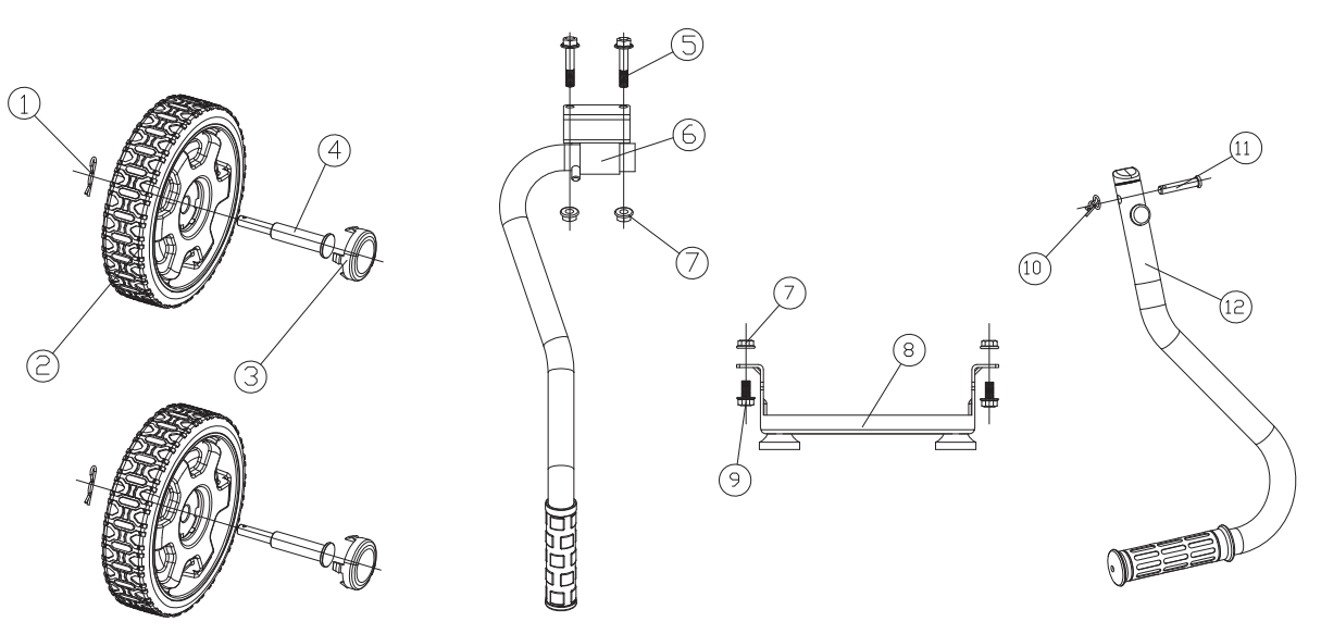
| # | Part Number | Description | Qty. |
| 1 | 2.16.001 | Pin Ø2 x 33, “R” Shape | 2 |
| 2 | 100714023-0001 | Wheel, Yellow | 2 |
| 3 | 100712243-0001 | Wheel, Cover, Yellow | 2 |
| 4 | 122.201501.23 | Roll Pin, Wheel, Ø16 x Ø10 x 97 | 2 |
| 5 | 1.5789.0845 | Flange Bolt M8 x 45 | 2 |
| 6 | 122.200700.01 | Handle Assembly | 1 |
| 7 | 1.6177.1.08 | Lock Nut M8 Flange | 4 |
| 8 | 100020978-0001 | Support Leg Assembly | 1 |
| 9 | 1.5789.0816 | Flange Bolt M8 x 16 | 2 |
| 10 | 100023415-0001 | R-pin R5 | 1 |
| 11 | 100011047-0003 | Roll Pin Ø8 x 40 | 1 |
| 12 | 100718155-0001 | Handle Assembly | 1 |
References
[xyz-ips snippet=”download-snippet”]