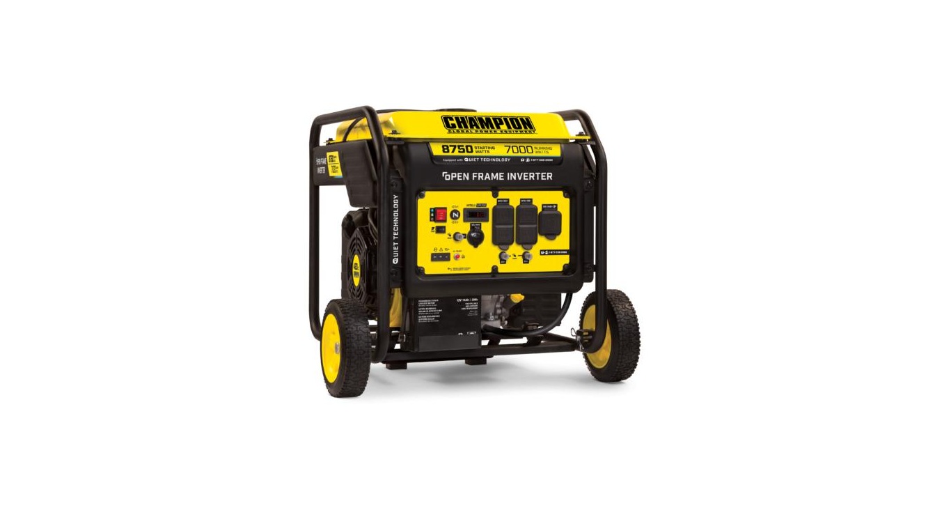
100520 8750W Open Frame Inverter
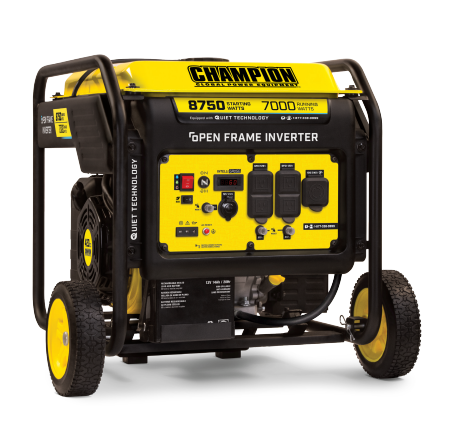
OPERATOR’S MANUALMODEL #100520 8750W OPEN FRAME INVERTERREGISTER YOUR PRODUCT ONLINE at championpowerequipment.comor visit championpowerequipment.com
SAVE THESE INSTRUCTIONS. This manual contains important safety precautions which should be read and understood before operating the product. Failure to do so could result in serious injury. This manual should remain with the product.Specifications, descriptions and illustrations in this manual are as accurate as known at the time of publication, but are subject to change without notice.
REV 20210803Champion Power Equipment, Inc., Santa Fe Springs, CA USA
INTRODUCTION
Congratulations on your purchase of a Champion Power Equipment (CPE) product. CPE designs, builds, and supports all of our products to strict specifications and guidelines. With proper product knowledge, safe use, and regular maintenance, this product should bring years of satisfying service.Every effort has been made to ensure the accuracy and completeness of the information in this manual at the time of publication, and we reserve the right to change, alter and/or improve the product and this document at any time without prior notice.CPE highly values how our products are designed, manufactured, operated, and serviced as well as providing safety to the operator and those around the generator. Therefore, it is IMPORTANT to review this product manual and other product materials thoroughly and be fully aware and knowledgeable of the assembly, operation, dangers and maintenance of the product before use. Fully familiarize yourself, and make sure others who plan on operating the product fully familiarize themselves too, with the proper safety and operation procedures before each use. Please always exercise common sense and always err on the side of caution when operating the product to ensure no accident, property damage, or injury occurs. We want you to continue to use and be satisfied with your CPE product for years to come.When contacting CPE about parts and/or service, you will need to supply the complete model and serial numbers of your product. Transcribe the information found on your product’s nameplate label to the table belowCPE TECHNICAL SUPPORT TEAM1-877-338-0999MODEL NUMBER100520SERIAL NUMBER
INTRODUCTIONSAFETY DEFINITIONS
The purpose of safety symbols is to attract your attention to possible dangers. The safety symbols, and their explanations, deserve your careful attention and understanding. The safety warnings do not by themselves eliminate any danger. The instructions or warnings they give are not substitutes for proper accident prevention measures.DANGERDANGER indicates a hazardous situation which, if not avoided, will result in death or serious injury.WARNINGWARNING indicates a hazardous situation which, if not avoided, could result in death or serious injury.CAUTIONCAUTION indicates a hazardous situation which, if not avoided, could result in minor or moderate injury.NOTICENOTICE indicates information considered important, but not hazard-related (e.g., messages relating to property damage).
DATE OF PURCHASEPURCHASE LOCATION
IMPORTANT SAFETY INSTRUCTIONS
WARNINGCancer and Reproductive Harm www.P65Warnings.ca.govDANGERGenerator exhaust contains carbon monoxide, a colorless, odorless, poisonous gas. Breathing carbon monoxide will cause nausea, dizziness, fainting or death. If you start to feel dizzy or weak, get to fresh air immediately.
OPERATE GENERATOR OUTDOORS ONLY IN A WELL VENTILATED AREA AND POINT EXHAUST AWAY.
DO NOT operate the generator inside any building, including garages, basements, crawlspaces and sheds, enclosure or compartment, including the generator compartment of a recreational vehicle. DO NOT allow exhaust fumes to enter a confined area through windows, doors, vents or other openings.DANGERUsing a generator indoors CAN KILL YOU IN MINUTES. Generator exhaust contains carbon monoxide. This is a poison you cannot see or smell. NEVER use inside a home or garage, EVEN IF doors and windows are open. ONLY use OUTSIDE and far away from windows, doors, and vents.Install battery-operated carbon monoxide alarms or plug-in carbon monoxide alarms with battery back-up according to the manufacturer’s instructions.
![]() WARNINGAlthough the generator contains a spark arrester, maintain a minimum distance of 5 ft. (1.5 m) from dry vegetation to prevent fires.
WARNINGAlthough the generator contains a spark arrester, maintain a minimum distance of 5 ft. (1.5 m) from dry vegetation to prevent fires.
IMPORTANT SAFETY INSTRUCTIONS
DANGEROperate equipment with guards in place. Rotating parts can entangle hands, feet, hair, clothing and/or accessories. Traumatic amputation or severe laceration can result.Keep hands and feet away from rotating parts. Tie up long hair and remove jewelry. DO NOT wear loose-fitting clothing, dangling drawstrings or items that could become caught.DANGERGenerator produces powerful voltage.DO NOT touch bare wires or receptacles. DO NOT use electrical cords that are worn, damaged or frayed. Use only Champion electrical cords for proper application. DO NOT operate generator in wet weather. DO NOT allow children or unqualified persons to operate or service the generator. Use a ground fault circuit interrupter (GFCI) in damp areas and areas containing conductive material such as metal decking. Connection to your home’s electrical system requires a listed 30A transfer switch installed by a licensed electrician and approved by the local authority having jurisdiction. The connection must isolate the generator from the utility power and must comply with all applicable laws and electrical codes.WARNINGDo not use generator for medical and life support uses.In case of emergency, call 911 immediately. NEVER use this product to power life support devices or life support appliances. NEVER use this product to power medical devices or medical appliances. Inform your electricity provider immediately if you or anyone in your household depends on electrical equipment to live. Inform your electrical provider immediately if a loss of power would cause you or anyone in your household to experience a medical emergency.
WARNINGSpark from removed spark plug wire can result in fire or electrical shock.When servicing the generator: Disconnect the spark plug wire and place it where it cannot contact the plug or any other metal object. DO NOT check for spark with the plug removed. Use only approved spark plug testers.WARNINGRunning engines produce heat. Severe burns can occur on contact. Combustible material can catch fire on contact.DO NOT touch hot surfaces. Avoid contact with hot exhaust gases. Allow equipment to cool before touching. Maintain at least 3 ft. (91.4 cm) of clearance on all sides to ensure adequate cooling. Maintain at least 5 ft. (1.5 m) of clearance from combustible materials.WARNINGRapid retraction of the starter cord will pull hand and arm towards the engine faster than you can let go. Unintentional startup can result in entanglement, traumatic amputation or laceration. Broken bones, fractures, bruises or sprains could result.When starting engine, pull the starter cord slowly until resistance is felt and then pull rapidly to avoid kickback. DO NOT start or stop the engine with electrical devices plugged in and turned on.CAUTIONExceeding the generator’s running capacity can damage the generator and/or electrical devices connected to it.DO NOT overload the generator. DO NOT tamper with the governed speed. DO NOT modify the generator in any way.
IMPORTANT SAFETY INSTRUCTIONS
CAUTIONStart the generator and allow the engine to stabilize before connecting electrical loads. Connect electrical equipment in the off position, and then turn them on for operation. Turn electrical equipment off and disconnect before stopping the generator.CAUTIONImproper treatment or use of the generator can damage it, shorten its life or void the warranty.Use the generator only for intended uses. Operate only on level surfaces. DO NOT expose generator to excessive moisture, dust, or dirt. DO NOT allow any material to block the cooling slots. If connected devices overheat, turn them off and disconnect them from the generator. DO NOT use the generator if: Electrical output is lost Equipment sparks, smokes or emits flames Equipment vibrates excessively
Fuel Safety
DANGERGASOLINE AND GASOLINE VAPORS ARE HIGHLY FLAMMABLE AND EXPLOSIVE.Fire or explosion can cause severe burns or death.
Gasoline and gasoline vapors:
- Gasoline is highly flammable and explosive.
- Gasoline can cause a fire or explosion if ignited.
- Gasoline is a liquid fuel but it’s vapors can ignite.
- Gasoline is a skin irritant and needs to be cleaned up immediately if spilled on skin or clothes.
- Gasoline has a distinctive odor, this will help detect potentialleaks quickly.
- Gasoline expands or contracts with ambient temperatures.Never fill the gasoline tank to full capacity, as gasoline needs room to expand when temperatures rise.
- In the case of any petroleum gasoline fire, flames should never be extinguished unless the fuel supply valve can be turned OFF. By not doing so, if a fire is extinguished and the supply of fuel is not turned OFF, an explosion hazard could be created.
When adding or removing gasoline: DO NOT light or smoke cigarettes. Always turn the generator off and let cool for a minimum of two minutes before removing the gasoline cap. Afterwards, loosen gasoline cap to relieve pressure from the gasoline tank. Only fill or drain gasoline outdoors in a well-ventilated area. DO NOT pump gasoline directly into the generator at the gas station. Always use an approved fuel container to transfer the gasoline to the generator. DO NOT overfill the gasoline tank. Always keep gasoline away from sparks, open flames, pilot lights, heat and other sources of ignition.When starting the generator: DO NOT attempt to start a damaged generator. Always make certain that the gasoline cap, air filter, spark plug, fuel lines and exhaust system are properly secured, connected and in place. Always allow spilled gasoline to evaporate fully before attempting to start the engine. Make certain that the generator is resting firmly on level ground.
When operating the generator: DO NOT move or tip the generator during operation. DO NOT tip the generator or allow fuel or oil to spill.When transporting or servicing the generator: Make certain that the fuel valve is in the OFF position and the gasoline tank is empty. Disconnect the spark plug wire.When storing the generator: Store away from sparks, open flames, pilot lights, heat and other sources of ignition. Do not store generator or gasoline near furnaces, water heaters, or any other appliances that produce heat or have automatic ignitions.WARNINGNever use a gasoline container, gasoline tank, or any other fuel item that is broken, cut, torn or damaged.
IMPORTANT SAFETY INSTRUCTIONS
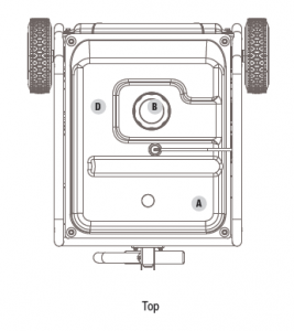
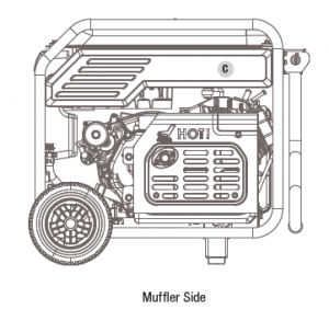
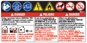
Safety LabelsThese labels warn you of potential hazards that can cause serious injury. Read them carefully. If a label comes off or becomes hard to read, contact Technical Support Team for possible replacement.
|
LABEL |
DESCRIPTION |
|
|
A |
|
Safety Symbols/ CO Danger |
|
B |
|
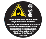
Fuel |
|
C |
|
Hot Surface |
|
D |
|
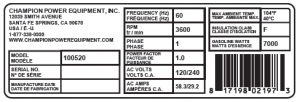
Dataplate |
IMPORTANT SAFETY INSTRUCTIONS
Safety Symbols
Some of the following symbols may be used on this product. Please study them and learn their meaning. Proper interpretation of these symbols will allow you to more safely operate the product.
|
SYMBOL |
MEANING |
|
|
Read Operator’s Manual. To reduce the risk of injury, user must read and understand operator’s manual before using this product. |
|
|
Clearance. Keep all objects at least 5 feet from generator. Heat from the muffler and exhaust gas can ignite combustible objects. |
|
|
Ground. Consult with local electrician to determine grounding requirements before operation. |
|
|
Electric Shock. Failure to use in dry conditions and to observe safe practices can result in electric shock. Improper connections to a building can allow current to backfeed into utility lines, creating an electrocution hazard. A transfer switch must be used when connecting to a building. |
|
|
Fire/Explosion. Fuel and its vapors are extremely flammable and explosive. Fire or explosion can cause severe burns or death. Keep generator at least 5 ft (1.5m) from all objects to prevent combustion. |
|
|
Hot Surface. To reduce the risk of injury or damage, avoid contact with any hot surface. |
|
|
Open Flame Alert. Fuel and its vapors are extremely flammable and explosive. Keep fuel away from smoking, open flames, sparks, pilot lights, heat, and other ignition sources. |
|
|
Wet Conditions Alert. Do not expose to rain or use in damp locations. |


IMPORTANT SAFETY INSTRUCTIONS
Operation SymbolsSome of the following symbols may be used on this product. Please study them and learn their meaning. Proper interpretation of these symbols will allow you to more safely operate the product.

![]()

IMPORTANT SAFETY INSTRUCTIONS
Quick Start Label SymbolsSome of the following symbols may be used on this product. Please study them and learn their meaning. Proper interpretation of these symbols will allow you to more safely operate the product.
![]()
Starting the EngineDANGERMove generator outside and far away from windows, doors and intake ventilation covers.
- Check oil level. Recommended oil is 10W-30.
- Check gasoline level. When adding gasoline, use a minimum octane rating of 87 and an ethanol content of 10% or less by volume.
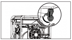
- Turn the fuel valve to “ON” position.
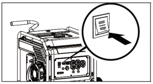
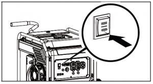
- Press the ignition switch to the “ON” position.
- Pull the choke to the “CHOKE” position.
- Pull the starter cord.
- Push choke button to the “RUN” position.
- Plug in desired device.
Stopping the Engine
- Turn off and unplug all connected electrical loads.
- Press the ignition switch to the “OFF” position.
- Turn the fuel valve to the “OFF” position. Electric Start See page 19 in “Operation” section.
CONTROLS AND FEATURES
CONTROLS AND FEATURESRead this operator’s manual before operating your generator. Familiarize yourself with the location and function of the controls and features. Save this manual for future reference.
Generator

- Reversal Valve
- Folding Handle Used to move unit by lifting and rolling onwheels. Do not use to lift or carry the unit.
- Fuel Valve Used to turn fuel supply on and off to engine.
- Air Filter Protects the engine by filtering dust and debrisfrom the intake air.
- Recoil Starter Used to manually start the engine.
- Never Flat Wheels 8 in. (20.3 cm).
- Battery Provides 12V DC power the starting system.
- Oil Fill Cap/Dipstick Used to check and fill oil level.
- Ground Terminal Consult an electrician for local grounding regulations.
- Quick Drain Tube Used to quickly drain engine oil.
- Control Panel See “Control Panel” section.
- Gasoline Tank 4.2 gal. (16 L).
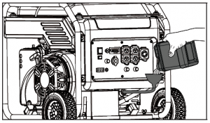
- Fuel Cap Remove to add fuel.
CONTROLS AND FEATURES
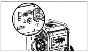
Control Panel
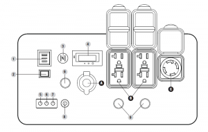
- Ignition Switch Used to put in START mode or STOP the generator.
- Economy Mode Switch Enables/disables automatic idle control.
- Choke Used to start a cold engine.
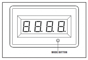
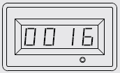
- Intelligauge Four mode digital meter for displaying voltage, frequency (hertz), run time, and total run time.
- Output Indicator Light Remains ON during normal operating conditions. Turns OFF when generator is overloaded.
- Overload Indicator Light When ON generator is overloaded and power to receptacles is cut.
- Oil Warning Indicator Light When ON engine will shut down and not run. Check oil level.
- AC Overload Reset Button Used to re-energize receptacles after overload fault.
- Circuit Breakers (Push Reset) Protects the generator against electrical overloads.

WARNINGDo not operate a device while it is plugged into the 12V DC outlet. Prolonged exposure to engine exhaust can cause serious injury or death. While charging a device do no place on the exhaust side of the generator. Extreme heat caused by exhaust can damage the device, and cause a potential fire hazard.
Intelligauge
Four mode digital meter for displaying voltage, frequency (hertz), run time, and total run time. The LCD displays each mode by pressing the button below the display.
|
MODE |
DESCRIPTION |
|
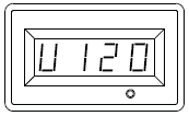
Voltage (V) |
Output voltage of the generator. |
|
Example: 120 volts |
|
|
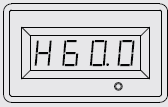
Frequency (H) |
Output frequency in hertz. |
|
Example: 60.0 hertz |
|
|
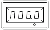
Run Time (R) |
Run time of the generator for the current session |
|
Example: 6 hours |
|
|
Total Run Time |
Total run time of the generator since first operation |
|
Example: 16 hours |
|
FCC Statement
- This device complies with Part 15 of the FCC Rules. Operation is subject to the following two conditions:1a. This device may not cause harmful interference.1b. This device must accept any interference received, including interference that may cause undesired operation.
- Changes or modifications not expressly approved by the party responsible for compliance could void the user’s authority to operate the equipment.
NOTICEThis equipment has been tested and found to comply with the limits for a Class B digital device, pursuant to Part 15 of the FCC Rules. These limits are designed to provide reasonable protection against harmful interference in a residential installation. This equipment generates uses and can radiate radio frequency energy and, if not installed and used in accordance with the instructions, may cause harmful interference to radio communications. However, there is no guarantee that interference will not occur in a particular installation. If this equipment does cause harmful interference to radio or television reception, which can be determined by turning the equipment off and on, the user is encouraged to try to correct the interference by one or more of the following measures: Reorient or relocate the receiving antenna. Increase the separation between the equipment andreceiver. Connect the equipment into an outlet on a circuit different from that to which the receiver is connected.Consult dealer or an experienced radio/TV technician for help.
CONTROLS AND FEATURES
Parts Included
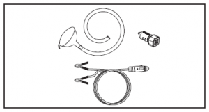
Accessories Flexible Oil Funnel – 1Dual 2.4A Port USB Adapter – 1Battery Charging Cables – 1
Assembly Parts
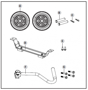
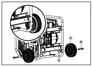
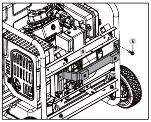
Wheels 8 in. (20.3 cm)Never Flat Wheel (A) – 2Roll Pin (B) – 2Large R-clip (C) – 2Engine Vibration Mounts Support Leg with Vibration Mounts (D) – 1Flange Bolt (M8×16) (E) – 2Folding Handle Handle (F) – 1Flange Bolt (M6×30) (G) – 4
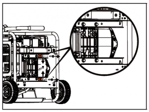
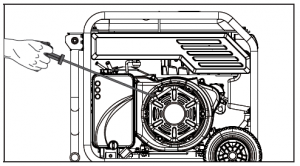
ASSEMBLYYour generator requires some assembly. This unit ships from our factory without oil. It must be properly serviced with fuel and oil before operation. If you have any questions regarding the assembly of your generator, call our Technical Support Team at 1-877-338-0999. Please have your serial number and model number available.Unpacking1. Set the shipping carton on a solid, flat surface. 2. Remove everything from the carton except the generator. 3. Carefully cut each corner of the box from top to bottom. Foldeach side flat on the ground to provide a surface area to work with the generator.Remove Shipping Support BracketsTo protect the generator during shipping, support brackets have been installed between the engine and frame. These brackets MUST BE REMOVED BEFORE adding oil or gasoline to the generator.NOTICEDO NOT attempt to run generator without first removing the shipping support brackets. Damage to the generator as a result of not removing the brackets will void the warranty.
- BEFORE filling the engine with oil or gasoline, tip the generator onto it’s recoil end. Tip onto the flattened cardboard box the generator came in or other protective surface so as to not scratch the frame.
- Remove the bolts from the orange support brackets. Bolts and brackets can be discarded.
- Tip the generator upright.
ASSEMBLY Install the Wheel KitCAUTIONThe wheel kit is not intended for over-the-road use.
Install the Wheels
- Before adding fuel and oil, tip the generator onto it’s end.
- Slide the roll pin (B) through the wheel (A) from the outside.
- Slide the roll pin through the mount point on the frame.
- Secure with the R-clip (C).
- Repeat to attach the second wheel.

Install the Support Leg
- Attach the support leg (D) to the generator frame with flange bolts (E).
- Slowly tip the generator back down so that it rests on the wheels and support leg.
Install the Handle
- Place the handle (F) over the mounting channel on the frame.
- Secure the handle to the frame using the four flangebolts (G).
Connect the Battery1. Remove the protective cover from the black (-) lead on the battery.2. Attach the black (-) lead to the black (-) terminal on the battery with the bolt and secure with the nut.
ASSEMBLY
NOTICEThe generator rotor has a sealed, pre-lubricated ball bearing that requires no additional lubrication for the life of the bearing.
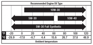
NOTICEThe recommended oil type for typical use is 10W-30 automotive oil.If running generator in extreme temperatures, refer to the following chart for recommended oil type.
- Place the generator on a flat, level surface.
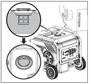
- Remove oil fill cap/dipstick to add oil.
- Using a funnel, add up to 37.2 fl. oz. (1.2 qt.) of oil (notincluded) and replace oil fill cap/dipstick. DO NOT OVERFILL.
- Check engine oil level at every use and add as needed.
Add Engine Oil
CAUTIONMAX DO NOT attempt to crank or start the engine before it has been properly filled with the recommended type and amount of oil. Damage to the generator as a result of failing to follow these instructions will void your warranty.
NOTICEOnce oil has been added, a visual check should show oil about 1-2 threads from running out of the fill hole. When using the dipstick to check oil level, DO NOT screw in the dipstick while checking.NOTICECheck oil level often during the break-in period. Refer to the Maintenance section for recommended service intervals.CAUTIONThis engine is equipped with a low oil shut-off and will stop when the oil level in the crankcase falls below the threshold level.NOTICEThe first 5 hours of run time are the break-in period for the unit. During the break in period stay at or below 50% of the running watt rating and vary the load occasionally to allow stator windings to heat and cool. Adjusting the load will also cause engine speed to vary slightly and help seat piston rings. After the 5 hour break-in period, change the oil.NOTICESynthetic oil may be used after the 5 hour initial break-in period. Using synthetic oil does not increase the recommended oil change interval. Full synthetic 5W-30 oil will aid in starting in cold ambient < 41º F (5º C) temperatures.
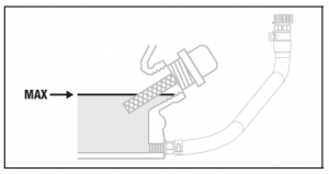
ASSEMBLYNOTICEIf no Max fill line is present on your unit’s metal tank neck as shown in picture, fill gasoline 1/2″ (12.7mm) above white tank filter.
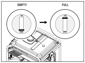
3. Fuel gauge on top of tank will read “F” when full of gasoline and “E” when tank is empty and needs to be refilled.
4. Screw on the gasoline cap and wipe away any spilled fuel.
Add FuelUse clean, fresh, regular unleaded gasoline with a minimum octane rating of 87 and an ethanol content of 10% or less by volume. y b cDO NOT mix oil with gasoline.1. Remove the gasoline cap.2. Slowly add gasoline to the tank. Tank is full when gasoline reaches the MAX fill line. DO NOT OVERFILL. Gasoline can expand after filling. A minimum of ¼ in. (6.4 mm) of space left in the tank is required for gasoline expansion, although more than ¼ in. (6.4 mm) is recommended. Gasoline can be forced out of the tank as a result of expansion if overfilled, and can affect the stable running condition of the generator.
OPERATION
CAUTIONUse unleaded gasoline with a minimum octane rating of 87 and an ethanol content of 10% or less by volume.DO NOT light cigarettes or smoke when filling the tank. DO NOT mix oil and gasoline. DO NOT overfill the tank. Fill tank to approximately ¼ in. (6.4 mm) below the top of the tank to allow for gasoline expansion. DO NOT pump gasoline directly into the generator at the pump. Use an approved container to transfer the gasoline to the generator. DO NOT fill tank indoors. DO NOT fill tank when the engine is running or hot.
A ground terminal connected to the frame of the generator has been provided (see Controls and Features for terminal location). For remote grounding, connect of a length of heavy gauge (12 AWG minimum) copper wire between the generator ground terminal and a copper rod driven into the ground. We strongly recommend that you consult with a qualified electrician to ensure compliance with local electrical codes.Neutral Floating*Neutral circuit IS NOT electrically connected to the frame/ ground of the generator.The generator (stator winding) is isolated from the frame and from the AC receptacle ground pin.Electrical devices that require a grounded receptacle pin connection will not function if the receptacle ground pin is not functional.
WARNINGPouring gasoline too fast through the fuel screen may result in gasoline splashing over the generator and operator while filling.NOTICEThe generator engine works well with 10% or less ethanol blend gasoline. When using ethanol-gasoline blends there are some issues worth noting:
Neutral Bonded to Frame* Neutral circuit IS electrically connected to the frame/ground ofthe generator. The generator system ground connects lower frame cross-member below the alternator. The system ground is connected to the AC neutral wire.* See your model’s control panel for specified type of grounding.
OPERATION
Ethanol-gasoline blends can absorb more water than gasoline alone.These blends can eventually separate, leaving water or a watery goo in the tank, fuel valve and carburetor. The compromised gasoline can be drawn into the carburetor and cause damage to the engine and/or potential hazards.If a fuel stabilizer is used, confirm that it is formulated to work with ethanol-gasoline blends.Any damages or hazards caused by using improper gasoline, improperly stored gasoline, and/or improperly formulated stabilizers, are not covered by manufacturer’s warranty.It is advisable to always shut off the gasoline supply and run the engine to starvation after each use. See Storage instructions for extended non-use.GroundingYour generator must be properly connected to an appropriate ground to help prevent electric shock.WARNING
Generator LocationNEVER operate the generator inside any building, including garages, basements, crawlspaces and sheds, enclosure or compartment, including the generator compartment of a recreational vehicle. Please consult your local authority. In some areas, generators must be registered with the local utility. Generators used at construction sites may be subject to additional rules and regulations. Generators should be on a flat, level surface at all times. (Even while not in operation) Generators must have at least 5 ft. (1.5 m) of clearance from all combustible material. In addition to clearance from all combustible material, generators must also have at least 3 ft. (91.4 cm) of clearance on all sides to allow for adequate cooling, maintenance and servicing. Generators should never be started or operated in the back of a SUV, camper, trailer, in the bed of a truck (regular, flat or otherwise), under staircases/stairwells, next to walls or buildings, or in any other location that will not allow for adequate cooling of the generator and/or the muffler. DO NOT contain generators during operation. Allow generators to properly cool before transport or storage.Place the generator in a well-ventilated area. DO NOT place the generator near vents or intakes where exhaust fumes could be drawn into occupied or confined spaces. Carefully consider wind and air currents when positioning generator.
Failure to properly ground the generator can result in electric shock.Failure to follow proper safety precautions may void manufacturer’s warranty.WARNINGDo not operate or store the generator in rain, snow, or wet weather.Using a generator or electrical appliance in wet conditions, such as rain or snow, or near a pool or sprinkler system, or when your hands are wet, could result in electrocution.WARNINGDuring operation the muffler and exhaust fumes will become hot. If adequate cooling and breathing space are not supplied, or if the generator is blocked or enclosed, temperatures can become extremely heated and may lead to fire.Surge ProtectionElectronic devices, including computers and many programmable appliances use components that are designed to operate within a narrow voltage range and may be affected by momentary voltage fluctuations. While there is no way to prevent voltage fluctuations, you can take steps to protect sensitive electronic equipment. Install UL1449, CSA-listed, plug-in surge suppressors on theoutlets feeding your sensitive equipment. Surge suppressors come in single- or multi-outlet styles. They’re designed to protect against virtually all short-duration voltage fluctuations.
Starting the Engine
- Make certain the generator is on a flat, level surface.
- Disconnect all electrical loads from the generator. Never start or stop the generator manually with electrical devices plugged in or turned on.
- Turn the gasoline fuel valve to the “ON” position.
- Pull the choke to the “CHOKE” position.
Electric Start
- Press and hold the ignition switch to the “START” position.Release as the engine begins to start. If the engine fails to start within five seconds, release the switch and wait at least ten seconds before attempting to start the engine again.
- Once engine starts, push choke button to the “RUN” position.
CAUTIONIf the ignition switch is held down in the “START” position longer than 5 seconds it could damage the starter.
Manual Start
1. Push the engine switch to the “ON” position.
 2. Pull choke button to “CHOKE” position.
 3. Pull the starter cord slowly until resistance is felt and then pull rapidly. Several pulls may be required.
4. Once engine starts, push choke button to the “RUN” position.
NOTICEKeep choke in “CHOKE” position for only 1 pull of the recoil starter. After first pull, press choke to “RUN” position for up to 3 pulls of the recoil starter. Too much choke leads to spark plug fouling/engine flooding due to lack of incoming air. This will cause the engine not to start.NOTICEFor gasoline restarts with hot engine in hot ambient temperature > 86°F (30°C), keep the choke in “CHOKE” position for only 1 pull of the recoil starter. After first pull, press choke to the “RUN” position for 3 more pulls of the recoil starter. Too much choke leads to spark plug fouling/engine flooding due to lack of incoming air. This will cause the engine not to start.NOTICEFor gas starting in cold ambient temperature < 59°F (15°C), the choke must be in 100% of “CHOKE” position for recoil start procedures. Do not over-choke. As soon as engine starts, press the choke button to the “RUN” position.NOTICEIf the engine starts but does not continue to run make certain that the generator is on a flat, level surface. This engine is equipped with a low oil sensor that will prevent the engine from running when the oil level falls below a critical threshold.
Connecting Electrical LoadsLet the engine stabilize and warm up for a few minutes after starting.Plug in and turn on the desired 120 or 240 (if applicable) Volt AC single phase, 60 Hz electrical loads. DO NOT connect 3-phase loads to the generator.
WARNINGConnecting a generator to your electric utility company’s power lines or to another power source may be against the law. In addition this action, if done incorrectly, could damage your generator and appliances and could cause serious injury or even death to you or a utility worker who may be working on nearby power lines. If you plan to run a portable electric generator during an outage, please notify your electric utility company immediately and remember to plug your appliances directly into the generator. Do not plug the generator into any electric outlet in your home. Doing so could create a connection to the utility company power lines. You are responsible for ensuring that your generator’s electricity does not feed back into the electric utility power lines.If the generator will be connected to a building electrical system, consult your local utility company or a qualified electrician. Connections must isolate generator power from utility power and must comply with all applicable laws and codes.
DO NOT overload the generator.
CapacityFollow these simple steps to calculate the running and starting watts necessary for your purposes:1. Select the electrical devices you plan on running at the same time.2. Total the running watts of these items. This is the amount of power you need to keep your items running.3. Identify the highest starting wattage of all devices identified in step 1. Add this number to the number calculated in step 2. Starting wattage is the surge of power needed to start some electric driven equipment. Following the steps listed under “Power Management” will guarantee that only one device will be starting at a time.
To prolong the life of your generator and attached devices, follow these steps to add electrical load:1. Start the generator with no electrical load attached.2. Allow the engine to run for several minutes to get up to temperature.3. Plug in and turn on the first item. It is best to attach the item with the largest load first.4. Allow the engine to stabilize.5. Plug in and turn on the next item.6. Allow the engine to stabilize.7. Repeat steps 5-6 for each additional item.NOTICENever exceed the specified capacity when adding loads to the generator.
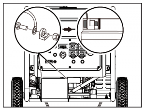
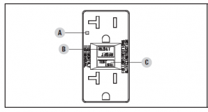
GFCIYour generator is equipped with ground fault circuit interrupter (GFCI) receptacles. In the event of a ground fault, a GFCI trips automatically to stop the flow of electricity and prevent serious injury. The green indicator light (A) on the receptacle will also turn off. Press the “RESET” (B) button located on the front of the receptacle to restore flow of electricity. The indicator light will also turn back on. GFCI does not protect against circuit overloads. To ensure proper operation of the GFCI duplex, perform this test monthly:
1. With the generator running, plug a lamp into the GFCI receptacle. Turn the lamp on.2. Press the “TEST” (C) button located on the front of the receptacle to trip the device. This should immediately stop the flow of electricity and shut off the lamp. If the electricity is not stopped, do not use this receptacle until is has been serviced or replaced.3. Press the “RESET” button located on the front of the receptacle to restore the flow of electricity. If the indicator light does not come back on or if the GFCI cannot be reset then it must be replaced.
Power ManagementUse the following formula to convert voltage and amperage to watts:
Volts × Amps = WattsEco (Economy) ModeThe Eco Mode switch can be activated to turn on economy control in order to minimize fuel consumption and noise while operating the unit during times of reduced electrical output. Eco Mode allows the engine speed to idle during periods of non-use.The engine speed returns to normal when an electrical load is connected. When the economy switch is off, the engine runs at normal speed continuously.
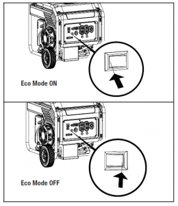 CAUTIONFor periods of high electrical load or momentary fluctuations, the Eco Mode should be off.12V DC Automotive Style OutletThe 12V DC outlet(s) can be used with the supplied accessories and other commercially available 12V DC automotive style plugs. The DC output is unregulated and can damage some products. Confirm the input voltage range of your item is at least 12-24V DC. When using the DC outlet turn the Eco Mode switch to the “OFF” position.WARNINGDo not operate a device while it is plugged in to the 12V DC outlet. Prolonged exposure to engine exhaust can cause serious injury or death.CAUTIONWhile charging a device do not place on the exhaust side of the generator. Extreme heat caused by exhaust can damage the device, and cause a potential fire hazard.
OPERATION
Battery Charging
- Before connecting the battery charging cable (included) to abattery that is installed in a vehicle, disconnect the vehicle battery ground cable from the negative () battery terminal.
- Plug the battery charging cable into the 12V DC receptacle of the generator.
- Connect the red (+) battery charger lead to the red (+) battery terminal.
- Connect the black () battery charger lead to the black () battery terminal.
- Start the generator. Important: The 12V DC outlet is ONLY to be used with the supplied 12V DC battery charging cable. The 12V DC output is unregulated and will damage other 12V DC products. When using the 12V DC outlet, turn the Economy mode switch to the “OFF” position. Be sure all electric devices including the lines and plug connections are in good condition before connection to the generator.
CAUTIONDo not start the vehicle while the battery charging cable is connected and the generator is running. It will not give the battery a boost of power. The vehicle or the generator may be damaged. Charge only vented wet lead acid batteries. Other types of batteries may burst, causing personal injury or damage.NOTICEBe sure all electric devices including the lines and plug connections are in good condition before connection to the generator.
Stopping the Engine1. Turn off and unplug all electrical connected loads. Never start or stop the generator with electrical devices plugged in or turned on.2. Let the generator run at no-load for several minutes to stabilize internal temperatures of the engine and generator.3. Press the engine switch to the “OFF” position.
In order to select the correct high altitude main jet it is necessary to identify the carburetor model. For this purpose, a code is stamped on the side of the carburetor. Select the correct high altitude jet part number corresponding to the carburetor code found on your particular carburetor.Carb. Code High Alt. Jet Part Number Min. Altitude16100Z98021200M016161-Z320410-00A0 16161-Z570210-00A03000 ft. (914 m) 6000 ft. (1829 m)
WARNINGOperation using the alternative main jet at elevations lower than the recommended minimum altitude can damage the engine. For operation at lower elevations, the originally supplied standard main jet must be used. Operating the engine with the wrong engine configuration at a given altitude may increase its emissions and decrease fuel efficiency and performance.
Important: Always ensure that the fuel valve and the engine switch are in the “OFF” position when the generator will not be used for an extended period of time.NOTICEIf the engine will not be used for a period of two (2) weeks or longer, please see the Storage section for proper engine and fuel storage.Operation at High AltitudeThe density of air at high altitudes is lower than at sea level. Engine power is reduced as the air mass and air-fuel ratio decrease. Engine power and generator output will be reduced approximately 3½% for every 1000 ft. of elevation above sea level. At high altitudes increased exhaust emissions can also result due to the increased enrichment of the air fuel ratio. Other high altitude issues can include hard starting, increased fuel consumption and spark plug fouling.To alleviate high altitude issues other than the natural power loss, CPE can provide a high altitude carburetor main jet. The alternative main jet and installation instructions can be obtained by contacting our Technical Support Team. Installation instructions are also available in the Technical Bulletin area of the CPE website.The part number and recommended minimum altitude for the application of the high altitude carburetor main jet is listed in the following table.
Moving the GeneratorNEVER lift or carry the generator using the folding handle. ALWAYS place the generator on its wheels in the uprightposition. ALWAYS turn the generator off and ensure the fuel valve isclosed. ALWAYS make sure engine and muffler are cooled downbefore the generator can be handled safely (typically 15-30 minutes). 1. Begin by raising the folding handle, found on opposite side of wheels. 2. Using the handle, tilt the end of the generator slightly off the ground until balanced on the wheels. 3. While maintaining balance, roll the generator to the desired location.NEVER tilt sideways while moving the generator.Failure to follow these instructions could result in personal injury or damage to the generator.MAINTENANCEMake certain that the generator is kept clean and stored properly. Only operate the unit on a flat, level surface in a clean, dry operating environment. DO NOT expose the unit to extreme conditions, excessive dust, dirt, moisture or corrosive vapors.WARNINGNever operate a damaged or defective generator.WARNINGImproper maintenance will void your warranty.NOTICEFor Emission control devices and systems, read and understand your responsibilities for service as stated in the Emission Control Warranty Statement of this manual.The owner/operator is responsible for all periodic maintenance. Complete all scheduled maintenance in a timely manner. Correct any issue before operating the generator. For service or parts assistance, contact our Technical Support Team at 1-877-338-0999.
Cleaning the Generator
CAUTIONDO NOT spray generator directly with water. Water can enter the generator through the cooling slots and damage the generator windings. It can also contaminate the fuel system.
- Use a damp cloth to clean exterior surfaces of the generator.
- Use a soft bristle brush to remove dirt and oil.
- Use an air compressor (25 PSI) to clear dirt and debris from the generator.
- Inspect all air vents and cooling slots to ensure that they areclean and unobstructed.
MAINTENANCETo prevent accidental starting, remove and ground the spark plug wire before performing any service.Changing the Engine OilChange oil when the engine is warm. Refer to the oil specification to select the proper grade for your operating environment.
- Unclip the quick drain oil tube from behind the panel andremove the oil drain cap.
- Allow the oil to drain completely into an appropriate container.
- Replace the oil drain cap.
- Remove the oil fill cap/dipstick to add oil.
- Add oil according to “Add Engine Oil” on Assembly section. DO NOT OVERFILL. Oil not included for routine maintenance.
- Dispose of used oil at an approved waste managementfacility.
NOTICEOnce oil has been added, a visual check should show oil about 1-2 threads from running out of the fill hole. If using the dipstick to check oil level, DO NOT screw in the dipstick while checking.
Cleaning and Adjusting the Spark Plug
- Remove the spark plug cable from the spark plug.
- Use a spark plug socket tool (not included), or a 13/16 in. (21 mm) socket (not included) to remove the plug.
- Inspect the electrode on the plug. It must be clean and not worn to produce the spark required for ignition.
- Make certain the spark plug gap is 0.028-0.031 in. (0.7-0.8 mm).
- Squeeze in a clean, absorbent cloth to remove all excess oil.
- Place the filter in the assembly.
- Reattach the air filter cover and snap in place.
Cleaning the Spark Arrestor
- Allow the engine to cool completely before servicing the spark arrestor.
- Remove the two or three screws (varies by model) holding the cover plate which retains the spark arrestor to the muffler.
- Remove the spark arrestor screen.
- Carefully remove the carbon deposits from the spark arrestorscreen with a wire brush.
- Refer to the spark plug types in Specifications when replacing the plug.
- Firmly re-install the plug.
- Attach the spark plug cable to the spark plug.
Cleaning the Air Filter
1. Remove the snap-on cover holding the air filter to the assembly.2. Remove the foam element.3. Wash in liquid detergent and water. Squeeze thoroughly dry in a clean cloth.4. Saturate in clean engine oil.* See your model’s parts list for specified type of spark arrestor.5. Replace the spark arrestor if it is damaged.6. Position the spark arrestor on the muffler and attach with thescrews removed in step 2.CAUTIONFailure to clean the spark arrestor will result in degraded engine performance.
NOTICEFederal and local laws and administrative requirements indicate when and where spark arrestors are required. When ordered, spark arrestors are required for operation of this generator in National Forest lands. In California, this generator must not be used on any forest-covered land, brush-covered land, or grass-covered land unless the engine is equipped with a spark arrestor.
STORAGE
Adjusting the Governor
* To be performed by knowledgeable, experienced owners or CPE certified service centers.
WARNINGTampering with the factory set governor will void your warranty.
The air-fuel mixture is not adjustable. Tampering with the governor can damage your generator and your electrical devices and will void your warranty. Contact our Technical Support Team at 1-877-338-0999 for all other service and/or adjustment needs.
STORAGE
DANGERGasoline vapors are highly flammable and extremely explosive.Fire or explosion can cause severe burns or death. Only fill or drain fuel outdoors in a well-ventilated area. DO NOT pump gasoline directly into the generator. Use an approved container to transfer the fuel to the generator. Never use a gasoline container, gasoline tank, or any other fuel item that is damaged or appears damaged. DO NOT overfill the gasoline tank. Always keep fuel away from sparks, open flames, pilot lights, heat and other sources of ignition. DO NOT light or smoke cigarettes.
Maintenance ScheduleFollow the service intervals indicated in the following maintenance schedule.Service your generator more frequently when operating in adverse conditions.Contact our Technical Support Team at 1-877-338-0999 to locate the nearest CPE certified service dealer for your generator or engine maintenance needs.
EVERY 8 HOURS OR PRIOR TO EACH USECheck oil levelClean around air intake and muffler
FIRST 5 HOURS (BREAK IN)Change oil
EVERY 50 HOURS OR ANNUALLYClean air filterChange oil if operating under heavy load or in hot environments
EVERY 100 HOURS OR ANNUALLYChange oilClean/adjust spark plugClean spark arrestorClean fuel valve filter*
EVERY 250 HOURSClean combustion chamber*Check/adjust valve clearance*
EVERY 3 YEARS Replace fuel line*Replace fuel line*
Short Term Storage (up to 30 days)Gasoline may gum up and clog the carburetor if the generator is not run or carburetor drained within 4 weeks.
1. Be sure all appliances are disconnected from the generator.2. Start the generator as instructed in Starting the Engine section.3. Turn the fuel valve to the “OFF” position.4. Let the engine run until fuel starvation has stopped the engine. This usually takes a few minutes.5. Move the engine switch to the “OFF” position.
Mid Term Storage (30 days 1 year)Gasoline in the tank has a maximum shelf life of up to 1 year with the addition of a properly formulated fuel stabilizer and stored in a cool, dry place.1. Be sure all appliances are disconnected from the generator.2. Add a properly formulated fuel stabilizer to the gasoline tank.3. Turn the fuel valve to the “ON” position.4. Start and run the generator for 10 minutes so the treated gasoline cycles through the fuel system.5. Option 1: Drain Gasoline from Carburetor5a. Turn engine switch to the “OFF” position and allow generator to cool completely before continuing.5b. Turn the fuel valve to the “OFF”.5c. Use the drain bolt on the carburetor to empty any excess gasoline from the carburetor into an appropriate container. Use a funnel (and appropriate hose if necessary) under the carburetor drain bolt to avoid spillage.5d. When gasoline stops flowing from the carburetor, replace and tighten the carburetor drain bolt and be sure to properly dispose of the drained gasoline according to local regulations or guidelines.6. Option 2: Run Dry 6a. With the generator running, turn the fuel valve to the “OFF” position and allow the generator to run until the engine stops from complete fuel starvation. This may take a few minutes. 6b. Turn engine switch to the “OFF” position and allow generator to cool completely before continuing.7. Remove the spark plug cap and spark plug and pour about a tablespoon of oil into the cylinder.8. Pull the recoil slowly to crank the engine to distribute the oil and lubricate the cylinder.9. Install the spark plug and spark plug cap.10. Clean the generator according to Cleaning the Generator.11. Store the generator in a cool, dry place out of direct sunlight.
Long Term Storage (over 1 year)For storage over 1 year, the gasoline tank and carburetor must be completely drained of gasoline. 1. Follow steps 1-4 according to Mid Term Storage.1a. Turn engine switch to the “OFF” position and allow generator to cool completely before continuing.2. Use the drain bolt on the carburetor to empty any excess gasoline from the gasoline tank and carburetor into an appropriate container. Use a funnel (and appropriate hose if necessary) under the carburetor drain bolt to avoid spillage.3. When gasoline stops flowing from the carburetor, replace and tighten the carburetor drain bolt and be sure to properly dispose of the drained gasoline according to local regulations or guidelines.4. Turn the fuel valve to the “OFF” position. 5. Follow steps 8-11 according to Mid Term Storage.
Removing from StorageIf the generator has been improperly stored for a long period of time with gasoline in the gasoline tank and/or carburetor, all fuel must be drained and the carburetor must be thoroughly cleaned. This process involves technically advanced tasks. For assistance please call our Technical Support Team at 1-877-338-0999.If the gasoline tank and carburetor were properly emptied of all gasoline prior to the generator being stored, follow the below steps when removing from storage.1. Be sure the engine switch is in the “OFF” position.2. Add gasoline to the generator according to Add Fuel: Gasoline.3. Turn the fuel valve to the “ON” position.4. After 5 minutes check the carburetor and air filter areas for any leaking gasoline. If any leaks are found, the carburetor will need to be disassembled and cleaned or replaced. If no gasoline leaks are found, turn the fuel valve to the “OFF” position.5. Check engine oil level and add clean, fresh oil if needed. See Oil Specifications for proper oil type.6. Check and clear air filter of any obstructions such as bugs or cobwebs. If necessary, clean air filter according to Cleaning the Air Filter.7. Start the generator according to Starting the Engine.
SPECIFICATIONS
Generator SpecificationsGenerator Model ……………………………………. 100520Start Type ………………………………….. Electric, ManualWatts (Starting/Running) ………………………… 8750/7000AC Volts…………………………………………….. 120/240AC Amps @ 120V ………………………………………. 58.3AC Amps @ 240V ………………………………………. 29.2DC Volts …………………………………………………. 12 DCAmps…………………………………………………… 8Frequency …………………………………………….. 60 HzPhase ………………………………………………… SingleWeight ……………………………………. 155.4 lb. (70.5 kg)Length …………………………………….. 26.6 in. (67.5 cm)Width ………………………………………. 25.6 in. (65 cm)Height……………………………………… 23.7 in. (60.1 cm)Engine SpecificationsModel ………………………………………………… R420PDisplacement ………………………………………… 420 ccType…………………………………………… 4-Stroke OHVSpark PlugOEM Type…………………………………………….. F6RTCReplacement Type…………………. NGK BPR6ES or equivalentGap …………………………….0.028-0.031 in. (0.7-0.8 mm)ValveIntake Clearance …………….. 0.002-0.006 in. (0.05-0.15 mm)Exhaust Clearance …………… 0.002-0.006 in. (0.05-0.15 mm)NOTICEA technical bulletin regarding valve adjustment procedures is available at www.championpowerequipment.com.
Oil SpecificationsDO NOT OVERFILL. Type……………………………………….. *See chart belowCapacity …………………………………. 37.2 fl. oz. (1.2 qt.)
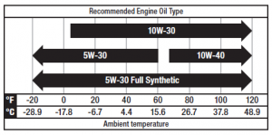
NOTICETemperature will affect engine oil and engine performance. Change the type of engine oil used based on the temperature to suit the engine needs.
Fuel SpecificationsUse unleaded gasoline with a minimum octane rating of 87 and an ethanol content of 10% or less by volume. DO NOT USE E15 or E85. DO NOT OVERFILL.Gasoline Capacity ……………………………… 4.2 gal. (16 L)Temperature SpecificationsStarting Temperature Range (°F/°C) ……….. 5 to 104/-15 to 40NOTICEAn important message about temperature: Your product is designed and rated for continuous operation at ambient temperatures up to 104°F (40°C). When needed, it may be operated at temperatures ranging from 5°F (-15°C) to 122°F (50°C) for short periods of time. If exposed to temperatures outside this range during storage, it should be brought back within this range before operation. In any event, the product must always be operated outdoors, in a well-ventilated area and away from doors, windows and vents.
TROUBLESHOOTING
|
Problem |
Cause |
Solution |
|
Engine will not start. |
No fuel. |
Add fuel. |
|
Faulty spark plug. |
Clean and adjust spark plug or replace. |
|
|
Low oil level. |
Fill crankcase to the proper level. |
|
|
Place generator on a flat, level surface. |
||
|
Spark plug wire loose. |
Attach wire to spark plug. |
|
|
Fuel valve is closed. |
Open fuel valve. |
|
|
Engine switch OFF. |
Press Engine switch ON. |
|
|
Old fuel or water in fuel. |
Drain fuel and replace with fresh fuel. |
|
|
Flooded with fuel. |
Let unit stand for 10 mins. |
|
|
Engine starts but runs roughly. |
Choke in the wrong position. |
Move choke until it stops under RUN position or push in completely. |
|
Dirty air filter. |
Clean or replace air filter. |
|
|
Dirty fuel valve. |
Clean the fuel valve. |
|
|
Clogged spark arrestor. |
Clean spark arrestor. |
|
|
Engine shuts down during operation. |
Out of fuel. |
Fill fuel tank. |
|
Low oil level. |
Fill crankcase to the proper level. Place generator on a flat, level surface. |
|
|
Clogged spark arrestor. |
Clean spark arrestor. |
|
|
Generator cannot supply enough power or overheating. |
Generator is overloaded. |
Review load and adjust. See “Connecting Electrical Loads.” |
|
Dirty air filter. |
Clean or replace air filter. |
|
|
Choke in wrong position. |
Move choke until it stops under RUN position or push in completely. |
|
|
Engine is running but no AC output. |
Poor cord connection. |
Check all connections. |
|
Circuit breaker is open. |
Reset circuit breaker. |
|
|
Loose wiring. |
Inspect and tighten wiring connections. |
|
|
GFCI tripped. |
Contact Reset GFCI receptacle breakers by pushing the TEST and RESET buttons until green LED illuminates. the help line. |
|
|
Other. |
Contact the help line. |
|
|
Engine hunts or falters. |
Engine governor defective. |
Contact the help line. |
|
Dirty fuel valve. |
Clean the fuel valve. |
|
|
Carburetor is dirty and running lean. |
Contact the help line. |
|
|
Choke in wrong position. |
Move choke until it stops under RUN position or push in completely. |
|
|
Repeated circuit breaker tripping. |
Overload. |
Review load and adjust. See “Connecting Electrical Loads.” |
|
Faulty power cords or device. |
Check for damaged, bare or frayed wires. Replace defective device. |
|
|
Circuit breaker still too hot. |
Let unit sit for 5 mins. |
For other issues and technical support:Technical Support Team Mon-Fri 8:30 AM-5:00 PM (PST/PDT) Toll Free 1-877-338-0999
WARRANTY*CHAMPION POWER EQUIPMENT 3 YEAR LIMITED WARRANTY
Other ExclusionsThis warranty excludes: Cosmetic defects such as paint, decals, etc.
Warranty QualificationsTo register your product for warranty and FREE lifetime call center technical support please visit: https://www.championpowerequipment.com/register To complete registration you will need to include a copy of the purchase receipt as proof of original purchase. Proof of purchase is required for warranty service. Please register within ten (10) days from date of purchase.Repair/Replacement WarrantyCPE warrants to the original purchaser that the mechanical and electrical components will be free of defects in material and workmanship for a period of three years (parts and labor) from the original date of purchase and 270 days (parts and labor) for commercial and industrial use. Transportation charges on product submitted for repair or replacement under this warranty are the sole responsibility of the purchaser. This warranty only applies to the original purchaser and is not transferable.Do Not Return The Unit To The Place Of PurchaseContact CPE’s Technical Service and CPE will troubleshoot any issue via phone or e-mail. If the problem is not corrected by this method, CPE will, at its option, authorize evaluation, repair or replacement of the defective part or component at a CPE Service Center. CPE will provide you with a case number for warranty service. Please keep it for future reference. Repairs or replacements without prior authorization, or at an unauthorized repair facility, will not be covered by this warranty.Warranty ExclusionsThis warranty does not cover the following repairs and equipment: Normal Wear Products with mechanical and electrical components need periodic parts and service to perform well. This warranty does not cover repair when normal use has exhausted the life of a part or the equipment as a whole. Installation, Use and Maintenance This warranty will not apply to parts and/or labor if the product is deemed to have been misused, neglected, involved in an accident, abused, loaded beyond the product’s limits, modified, installed improperly or connected incorrectly to any electrical component. Normal maintenance is not covered by this warranty and is not required to be performed at a facility or by a person authorized by CPE.
Wear items such as filter elements, o-rings, etc.Accessory parts such as starting batteries, and storage covers.Failures due to acts of God and other force majeure events beyond the manufacturer’s control.Problems caused by parts that are not original Champion Power Equipment parts.When applicable, this warranty does not apply to products used for prime power in place of a utility.Limits of Implied Warranty and Consequential DamageChampion Power Equipment disclaims any obligation to cover any loss of time, use of this product, freight, or any incidental or consequential claim by anyone from using this product. THIS WARRANTY AND THE ATTACHED U.S. EPA and/or CARB EMISSION CONTROL SYSTEM WARRANTIES (WHEN APPLICABLE) ARE IN LIEU OF ALL OTHER WARRANTIES, EXPRESS OR IMPLIED, INCLUDING WARRANTIES OF MERCHANTABILITY OR FITNESS FOR A PARTICULAR PURPOSE. A unit provided as an exchange will be subject to the warranty of the original unit. The length of the warranty governing the exchanged unit will remain calculated by reference to the purchase date of the original unit. This warranty gives you certain legal rights which may change from state to state or province to province. Your state or province may also have other rights you may be entitled to that are not listed within this warranty.Contact InformationAddress Champion Power Equipment, Inc. 12039 Smith Ave. Santa Fe Springs, CA 90670 USA www.championpowerequipment.com Customer Service Mon Fri 8:30 AM 5:00 PM (PST/PDT) Toll Free: 1-877-338-0999 Fax no.: 1-562-236-9429 Technical Service Mon Fri 8:30 AM 5:00 PM (PST/PDT) Toll Free: 1-877-338-0999 24/7 Tech Support: 1-562-204-1188
*Except as otherwise stipulated in any of the following enclosed Emission Control System Warranties (when applicable) for the Emission Control System: U.S. Environment Protection Agency (EPA) and/or California Air Resources Board (CARB). Whichever warranty applies for the longer period, either this 3 year limited warranty or the applicable Emission Control System Warranty, shall supersede the other.
CHAMPION POWER EQUIPMENT, INC. (CPE), THE UNITED STATES ENVIRONMENTAL PROTECTION AGENCY (U.S. EPA) AND THE CALIFORNIA AIR RESOURCES BOARD (CARB) EMISSION CONTROL SYSTEM WARRANTYYour Champion Power Equipment (CPE) engine complies with both the U.S. EPA and state of California Air Resources Board (CARB) emissions regulations.YOUR WARRANTY RIGHTS AND OBLIGATIONS:The US EPA, California Air Resources Board, and CPE are pleased to explain the Federal and California Emission Control Systems warranty on your 2021 small off-road engine (SORE) and equipment. In the United States and California, new small off-road engines (SORE) and new equipment that use small off-road engines (SORE) must be designed, built and equipped to meet the State’s stringent anti-smog standards.CPE must warrant the emission control system on your small off-road engine (SORE) and equipment for the period of time listed below, provided there has been no abuse, neglect or improper maintenance of your small off-road engine (SORE) and equipment leading to the failure of the emission control system.Your emission control system may include parts such as the carburetor, fuel-injection system, the ignition system, catalytic converter, fuel tanks, fuel lines (for liquid fuel and fuel vapors), fuel caps, valves, canisters, filters, clamps, connectors, and other associated components. Also included may be hoses, belts, and other emission related assemblies. Where a warrantable condition exits, CPE will repair your small off-road engine (SORE) and equipment at no cost to you including diagnosis, parts and labor.MANUFACTURER’S WARRANTY COVERAGE:This Emissions Control System is warranted for two years. If any emissions-related part on your small off-road engine (SORE) and equipment is defective, the part will be repaired or replaced by CPE.OWNER WARRANTY RESPONSIBILITIES:As the small off-road engine (SORE) and equipment owner, you are responsible for the performance of the required maintenance listed in your Owner’s Manual. CPE recommends that you retain all your receipts covering maintenance on your small off-road engine (SORE) and equipment, but CPE cannot deny warranty coverage solely for the lack of receipts or for your failure to ensure the performance of all scheduled maintenance.As the small off-road engine (SORE) and equipment owner, you should be aware that CPE may deny you warranty coverage if your small off-road engine (SORE) and equipment or a part has failed due to abuse, neglect, improper maintenance or unapproved modifications.You are responsible for presenting your small off-road engine (SORE) and equipment to an Authorized CPE service outlet or alternate service outlet as described in (3)(f.) below, CPE dealer or CPE, Santa Fe Springs, Ca. as soon as a problem exists. The warranty repairs shall be completed in a reasonable amount of time, not to exceed 30 days.If you have any questions regarding your warranty coverage, you should contact:Champion Power Equipment, Inc. Customer Service 12039 Smith Ave.Santa Fe Springs, CA 90670 1-877-338-0999
EMISSION CONTROL SYSTEM WARRANTYThe following are specific provisions relative to your Emission Control System (ECS) Warranty Coverage.1. APPLICABILITY: This warranty shall apply to 1995 and later model year California small off-road engines (SORE) (for other states, 1997 and later model year engines). The ECS Warranty Period shall begin on the date the new engine or equipment is delivered to its original, end-use purchaser, and shall continue for 24 consecutive months thereafter.2. GENERAL EMISSIONS WARRANTY COVERAGE CPE warrants to the original, end-use purchaser of the new engine or equipment and to each subsequent purchaser that each of its small off-road engines (SORE) is:2a. Designed, built and equipped so as to conform to U.S. EPA emissions standards for spark- ignited engines at or below 19 kilowatts and all applicable regulations adopted by the California Air Resources Board; and2b. Free from defects in materials and workmanship that cause the failure of a warranted part to be identical in all material respects to the part as described in the engine manufacturer’s application for certification for a period of two years.3. THE WARRANTY ON EMISSION-RELATED PARTS WILL BE INTERPRETED AS FOLLOWS:3a. Any warranted part that is not scheduled for replacement as required maintenance in the Owner’s Manual shall be warranted for the ECS Warranty Period. If any such part fails during the ECS Warranty Period, it shall be repaired or replaced by CPE according to Subsection “d” below. Any such part repaired or replaced under the ECS Warranty shall be warranted for a time not less than the remainder of the ECS Warranty Period.3b. Any warranted, emissions-related part which is scheduled only for regular inspection as specified in the Owner’s Manual shall be warranted for the ECS Warranty Period. A statement in such written instructions to the effect of “repair or replace as necessary” shall advise owners of the warranty coverage for emission related parts. Replacement within the warranty period is covered by the warranty and shall not reduce the ECS Warranty Period. Any such part repaired or replaced under the ECS Warranty shall be warranted for a time not less than the remainder of the ECS Warranty Period.3c. Any warranted, emissions-related part which is scheduled for replacement as required maintenance in the Owner’s Manual shall be warranted for the period of time prior to the first scheduled replacement point for that part. If the part fails prior to the first scheduled replacement, the part shall be repaired or replaced by CPE according to Subsection “d” below. Any such emissionsrelated part repaired or replaced under the ECS Warranty, shall be warranted for a time not less than the remainder of the ECS Warranty Period prior to the first scheduled replacement point for such emissions-related part.3d. Repair or replacement of any warranted, emissions-related part under this ECS Warranty shall be performed at no charge to the owner at a CPE Authorized Service Outlet.3e. The owner shall not be charged for diagnostic labor which leads to the determination that a part covered by the ECS Warranty is in fact defective, provided that such diagnostic work is performed at a CPE Authorized Service Outlet.3f. CPE shall pay for covered emissions warranty repairs at non-authorized service outlets under the following circumstances:i. The service is required in a population center with a population over 100,000 according to U.S. Census 2000 without a CPE Authorized Service Outlet ANDii.The service is required more than 100 miles from a CPE Authorized Service Outlet. The 100 mile limitation does not apply in the following states: Alaska, Arizona, Colorado, Hawaii, Idaho, Montana, Nebraska, Nevada, New Mexico, Oregon, Texas, Utah and Wyoming.3g. CPE shall be liable for damages to other original engine components or approved modifications proximately caused by a failure under warranty of an emission-related part covered by the ECS Warranty.3h. Throughout the ECS Warranty Period, CPE must maintain a supply of warranted emission-related parts sufficient to meet the expected demand for such emission-related parts and must obtain additional parts if that supply is exhausted.3i. Any CPE Authorized and approved emission-related replacement part that do not increase the exhaust or evaporative emissions of the engine or emissions control system may be used in the performance of any ECS Warranty maintenance or repair and will be provided without charge to the owner. Such use shall not reduce CPE’s warranty obligation.3j. Unapproved add-on or modified parts may not be used to modify or repair a CPE engine. Such use voids this ECS Warranty and shall be sufficient grounds for disallowing an ECS Warranty claim. CPE shall not be liable hereunder for failures of any warranted parts of a CPE engine caused by the use of such an unapproved add-on or modified part.
EMISSION-RELATED PARTS INCLUDE THE FOLLOWING: (using those portions of the list applicable to the engine)
Systems covered by this warrantyFuel Metering System Air Induction System Ignition System Exhaust System Miscellaneous Parts Evaporative Emissions
Parts DescriptionFuel regulator, Carburetor and internal parts Air cleaner, Intake manifold Spark plug and parts, Magneto ignition system Exhaust manifold, catalytic converter Tubing, Fittings, Seals, Gaskets, and Clamps associated with these listed systems. Fuel Tank, Fuel Cap, Fuel Lines (for liquid fuel and fuel vapors), Fuel Line Fittings, Clamps, Pressure Relief Valves, Control Valves, Control Solenoids, Electronic Controls, Vacuum Control Diaphragms, Control Cables, Control Linkages, Purge Valves, Gaskets, Liquid/Vapor Separator, Carbon Canister, Canister Mounting Brackets, Carburetor Purge Port Connector
TO OBTAIN WARRANTY SERVICE:You must take your CPE engine or the product on which it is installed, along with your warranty registration card or other proof of original purchase date, at your expense, to any Champion Power Equipment dealer who is authorized by Champion Power Equipment, Inc. to sell and service that CPE product during his normal business hours. Alternate service locations defined in Section (3)(f.) above must be approved by CPE prior to service. Claims for repair or adjustment found to be caused solely by defects in material or workmanship will not be denied because the engine was not properly maintained and used.If you have any questions regarding your warranty rights and responsibilities, or to obtain warranty service, please write or call Customer Service at Champion Power Equipment, Inc.Champion Power Equipment, Inc. 12039 Smith Ave.Santa Fe Springs, CA 90670 1-877-338-0999Attn.: Customer Service
[xyz-ips snippet=”download-snippet”]