Champion Power Equipment, Inc., Santa Fe Springs, CA USAModel #201001PARTS INFORMATION5500W WIReleSS ReMOTe START INveRTeR GeNeRATORSeRIAl NUMBeR RANGe: All
shop.championpowerequipment.com or call 1-877-338-0999.
INveRTeR GeNeRATOR PARTS DIAGRAM
INVERTER GENERATOR PARTLIST
# Part Number Description Oty.
1
1.5789.0615
Flange Bolt M6 x 15
3
2
63.200600.00
Base Setting Component Assembly, See Figure H
1
3
63.210000.02
Control Panel Assembly, See Figure G
1
4
63.070000.01
Fuel Tank Assembly, See Figure F
1
5
5.1900.137
Battery SAE Wire
1
6
122.200013.04
Sheath, Rubber, Black
1
7
122.200013.04.3
Sheath, Rubber, Red
1
8
63.200902.00
Pinch
1
9
9.1000.090
Battery, 9AH
1
10
63.200503.00
Cover, Connect Port
6
11
2/5/1950
Clamp, Wire, 100
3
12
1.6177.1.08
Lock Nut M8, Flange
14
13
2/5/1901
Clamp, 08 x 6.5
2
14
2/6/1906
Clamp, 07 x 01
1
15
2/6/1904
Clamp, 08 x 01
1
16
1.818.0514.1
Screw M5x14
22
17
63.200700.00
Handle Assembly
1
18
63.200509.00
Handle, Pin
1
19
2/3/1966
Bushing, 010.5 x 021 x 2
2
20
2/16/1906
Cotter Pin02x20)
1
21
2/2/1910
Cage Nut M5
20
22
1.5789.0612
Flange Bolt M6 x 12
18
23
1.5789.0512
Flange Bolt M5 x 12
5
24
63.220004.00
Holder, Control Unit
2
25
63.221000.00
Control Unit, 4.0KW, 120V/60Hz, Wireless Parallel
1
26
5.1800.009
Rectifier
1
27
63.200018.01
Support Arm
1
28
63.201100.01
Supporter, Left
1
29
1.845.3595
Screw, ST3.5 x 9.5
2
30
1.5789.0610
Flange Bolt M6 x 10
4
31
63.080600.00
Protector Assembly, Lower
1
32
64.
Engine, 224 cc, See Figure B
1
33
63.201600.03
Supporter, Fuel Tank
2
34
63.200401.01
Supporter, Rear Cover, Black
1
35
1.845.4216
Screw, ST4.2 x 16
29
36
63.200101.01
Supporter, Front Cover, Black
1
37
2.08.075.1
Bolt M6 x 20
6
38
63.200101.00
Front Cover
1
39
63.200103.00
Rubber Sleeve
2
40
63.200402.01
Protector, Rear Cover
1
41
1.6177.1.06
Lock Nut M6, Flange
2
42
63.200410.01
Cover Rotary Knob
2
43
63.200410.00
Rotary Knob, Protector, Rear Cover
2
44
1.823.0325
Screw M3x25
2
45
63.200700.01
Handle
2
46
63.213004.02
Rubber Pad
1
47
63.200502.00
Spillway, Fuel Tank
1
48
63.214000.00
Indicator Light Assembly, Fuel Tank
1
49
63.200102.00
Rubber Sleeve
4
50
5.1900.139
Motor SAE Wire
1
51
152.200013.03
Sleeve, Connector
2
52
152.200013.02.3
Sheath, Rubber, Red
1
53
26.100001.00
Gasket, Exhaust
1
54
2.08.179.1
Flange Bolt M6 x 25
4
55
63.200500.00
Cover, Top, Black
1
56
2/6/1918
Clamp, 010.5 x b8
3
57
2.08.102
Screw M6x13
1
58
63.070011.01
Fuel Pipe, Fuel Valve To Carburetor
1
59
2.08.168
Bolt
2
60
63.201100.02
Supporter, Right
1
61
63.081100.00
Muffler Protector Assembly, Front
1
62
63.101005.00
Supporter, Muffler Assembly
1
63
63.101000.00.2
Muffler Assembly
1
64
63.081200.00
Muffler Protector Assembly, Rear
1
65
63.200401.00
Supporter, Rear Cover, Black
1
66
2/3/1969
Retaining Ring, M5
6
67
63.200304.00
Rubber Seal, Muffler Cover
1
68
63.200303.00
Muffler Cover
1
69
63.200302.00
Cover, Right Side, Black
1
70
63.200018.00
Support Arm
1
71
122.070700.00
Carbon Canister, 320CC
1
72
63.070014.01
Pipe, Fuel Tank To Canister
1
73
63.070013.00
Pipe, Canister To Air Cleaner
1
74
9.2600.002
Remote
1
75
9.1700.008
“Plug, USB 5V/2.4A”
1
76
1.16674.0812
Flange Bolt M8 x 12
4
77
63.200200.00
Cover, Left
1
78
24.070030.00
Hole, Breather Tube
1
ENGINE PARTS DIAGRAM FIGURE B
ENGINE PARTS LIST
# Part Number Description Oty.
1
1.5789.0612
Flange Bolt M6 x 12
11
2
62.061300.00
Handle, Recoil, Soft
1
3
63.061200.00
Handle guide plate
1
4
83.061100.01.1
Cover, Recoil Starter, Black
1
5
21.061005.00
Spring, Recoil Starter
1
6
2.10.001.1
Rope 04×1570, Black
1
7
21.061001.01
Reel, Recoil Starter
1
8
45.060003.00
Spring, Ratchet
2
9
45.060002.00
Starter Ratchet, Steel
2
10
45.060009.00
Spring Guide, Ratchet
1
11
45.060007.00
Ratchet Guide
1
12
45.060008.00
Screw, Ratchet Guide
1
13
2/5/1950
Clamp, Wire, 100
2
14
1.5789.0620
Flange Bolt M6 x 20
4
15
63.080100.00
Fan Cover
1
16
63.061000.00
Recoil Assembly
1
17
63.090004.02
Air Cleaner Tube
1
18
63.090003.00
Joint, Breather Pipe
1
19
63.090005.00
Pinch, Air Cleaner Tube
1
20
1.16674.0610
Flange Bolt M6 x 10
3
21
63.060001.00
Pulley, Starter
1
22
1.16674.0616
Flange Bolt M6 x 16
4
23
182.060002.00
Connecting Base
1
24
63.080001.00
Cooling Fan
1
25
2/2/1906
Nut M14 x 1.5
1
26
63.191100.00
Rotor
1
27
63.191200.00
Stator Component
1
28
211.
Oil Seal 025 x 041.3 x 6
1
29
62.200410.00
Rotary Knob, Protector, Rear Cover
1
30
182.030006.00
Pinch
1
31
1.5789.0608
Flange Bolt M6 x 08
1
32
63.030006.01
Pinch
1
33
63.030032.00
Sheath, Wire
1
34
63.030100.00.1
Crankcase
1
35
21.127000.02
Oil Level Sensor
1
36
63.091200.00
Cover, Air Cleaner
1
37
27.050200.00
Connecting Rod
1
38
27.050100.04
Crankshaft
1
39
24.030008.00
Gasket, Crankcase Cover
1
40
27.030013.00
Seal Strip, Crankcase Cover, Long
1
41
27.030013.01
Seal Strip, Crankcase Cover, Short
1
42
63.030007.00
Cover, Crankcase
1
43
63.031000.00.2
Oil Dipstick Assembly
1
44
1.5789.0832
Flange Bolt M8 x 32
6
45
1.16674.0620
Flange Bolt M6 x 20
2
46
63.123000.01
Ignition Coil, Silicon Rubber
1
47
63.091003.00
Element, Air Cleaner
1
48
63.080300.00
Air Guide
1
49
2/3/1916
Washer 010 x 016 x 1.5, Drain Bolt
1
50
83.032000.00
Hose, Oil Drain
1
51
2/6/1913
Clamp
1
52
45.030200.00
Support
1
53
1.6177.06
Flange Nut M6
2
54
24.130004.20
Gasket, Air Cleaner
1
55
1.5789.0625
Flange Bolt M6 x 25
2
56
63.130000.02
Carburetor Assembly, See Figure D
1
57
22.130003.00
Gasket, Carburetor
1
58
63.130001.00
Insulator, Carburetor
1
59
24.130002.00
Gasket, Insulator
1
60
25.040013.00
Lifter, Valve
2
61
2/4/1901
Dowel Pin 09 x 14
2
62
27.041000.00
Camshaft
1
63
2/14/1912
Woodruff Key 4 x 7.5 x 19
1
64
1.276.6205.9
Bearing 6205
2
65
27.050005.00
Piston
1
66
23.050003.00
Pin, Piston
1
67
2/9/1901
Circlip 018 x 01
2
68
27.050303.00
Ring, Oil
1
69
27.050302.00
Ring, Second Piston
1
70
27.050301.00
Ring, First Piston
1
71
27.030009.01
Gasket, Cylinder Head
1
72
2/4/1903
Dowel Pin 010 x 14
2
73
63.010000.00
Cylinder Head Assembly, See Figure C
1
74
1.16674.0512.2
Flange Bolt M5 x 12
4
75
1.823.0512
Screw M5 x 12
2
76
2.15.002(F6RTC)
Spark Plug F6RTC
1
77
1.5789.0865
Flange Bolt M8 x 65
3
78
63.125200.01
Relay, Starter
1
79
63125100.00
Starter Motor
1
80
63.125000.01
Starter Motor Assembly
1
81
1.5789.0655
Flange Bolt M6 x 55
3
82
21.040008.00
Rotator, Exhaust Valve
1
83
24.040202.00
Shaft, Rocker Arm
1
84
22.040009.00
Rocker Arm
2
85
22.040012.00
Screw, Valve Adjustment
2
86
21.040021.00
Nut M6 x 0.5, Lock
2
87
1.97.1.06
Washer 06
2
88
1.6177.1.06
Lock Nut M6, Flange
2
89
23.020001.03
Breather Tube
1
90
24.040201.00
Retainer, Rocker Arm
1
91
63.091000.00
Air Cleaner Assembly
1
92
24.040004.00
Guide Plate, Push Rod
1
93
27.040005.00
Push Rod
2
94
63.091100.00
Base, Air Cleaner
1
95
63.080200.00
Air Shroud, Cylinder
96
2.08.121
Flange Bolt M10 x 65
1
97
1.5789.0615
Flange Bolt M6 x 15
4
98
85.021101.00
Cover, Cylinder Head
1
99
85.030300.00
Ventilation Chamber Cover Assembly
1
100
85.030022.00
Gasket, Ventilation Chamber Cover
4
101
85.020002.00
Gasket, Cylinder Head Cover
1
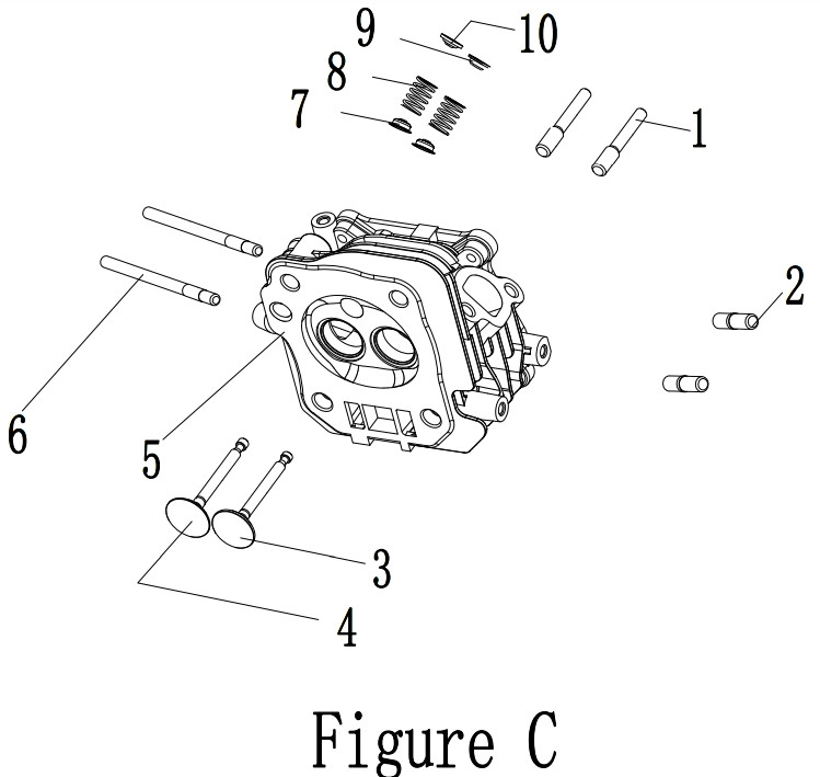
CYLINDER HEAD DIAGRAM CylINDER HEAD lIST
#
Part Number
Description
City.
1
23.040010.00
Bolt, Rocker Arm
2
2
2/1/1910
Stud Bolt M8 x 35
2
3
23.040006.02
Valve, Exhaust
1
4
23.040002.02
Valve, Intake
1
5
26.010100.01
Cylinder Head, 224cc
1
6
2/1/1949
Stud Bolt M6 x 99
2
7
23.040017.00
Oil Seal, Valve, Steel
2
8
21.040003.00
Spring, Valve
2
9
21.040007.00
Retainer, Exhaust Valve Spring
1
10
21.040001.00
Retainer, Intake Valve Spring
1
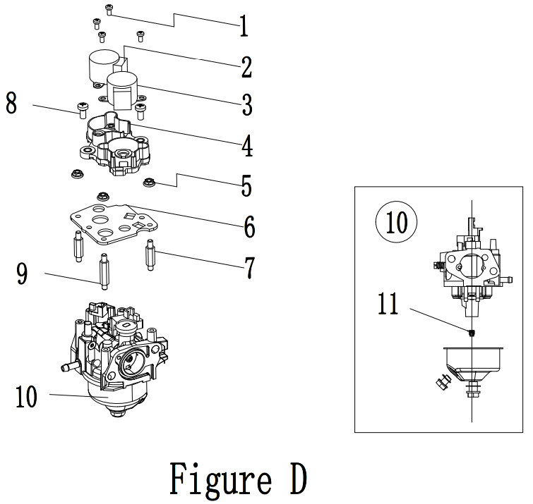
CARBURETOR DIAGRAM CARBURETOR lIST
#
Part Number
Description
Oty.
1
1.823.04081
Screw M4 x 8
4
2
45.132200.03
Stepper Motor
1
3
62.132200.00
Stepper Motor
1
4
85.132100.03
Support, Stepper Motor
1
5
1.61771.04.2
Lock Nut M4, Flange
3
6
85.130005.03
Support, Stepper Motor
1
7
85130006.
Support 15mm, Support plate
2
8
1.9074.4.05121
Screw M5 x 12, Black
2
9
85.130006.04
Support 20mm, Support plate
1
10
63.131000.02
Carburetor
1
11
63131017.00
Standard Main Jet
1
63.131017.00.01
Altitude Main Jet
/
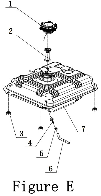
FUEL TANK DIAGRAM
FUEL TANK lIS
#
Part Number
Description
Qty.
1
122.070100.09
Fuel Tank Cap
1
2
63.070300.00
Fuel Filter, Fuel Pipe
1
3
63.070015.00
Mount Vibration, Fuel Tank
4
4
63.070600.00
Connect
1
5
2/6/1918
Clamp, 010.5 x b8
1
6
63.070011.00
Fuel Pipe, Fuel Tank To Fuel Valve
1
7
63.071000.01.1
Fuel Tank
1
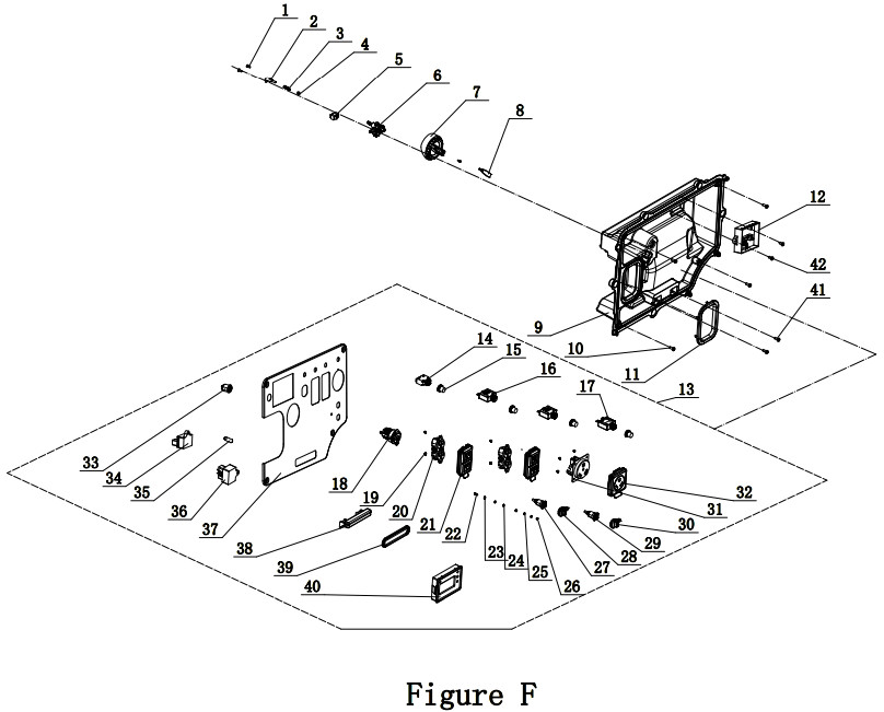
OUTlET PANEL DIAGRAM OUTLET PANEL LIST
Part Number
Description
Qty.
1
1.823.0412.1
Screw M4x12
3
2
62.139006.00
Pressure Plate
1
3
62.139007.00
Spring, Steel Ball
1
4
62.139008.00
Ball Bearing, Rotary Knob
1
5
5.1050.006
Microswitch
1
6
63.070400.00
Fuel Valve
1
7
63139001.00
Rotary Knob
1
8
62.139002.00.48
Cover Rotary Knob
1
9
63.210002.00
Control Box
1
10
1.9074.4.0512.1
Screw/Washer Assembly M5 x 12, Black
4
11
63.200106.00
Protector, Front Cover
1
12
5.1830.030
Remote Module
1
13
201001.
Control Panel
1
14
5.1200.308
8 Amp Circuit Breaker, Push Button
1
15
5.1870.014
Circuit Breaker Cover, Push Button
4
16
5.1210.920
20 Amp Circuit Breaker, Push Button
2
17
5.1210.930
30 Amp Circuit Breaker, Push Button
1
18
5.1110.005
Receptacle, DC.12V
1
19
1.61771.04.1
Lock Nut M4, Flange
8
20
5.1120.010
Receptacle 5-20R, Duplex
2
21
5.1870.025
Receptacle Cover, Receptacle 5-20R, Duplex
2
22
1.5783.0520.1
Bolt M5 x 20, Black
1
23
1.862.05
Lock Washer 05, Toothed
1
24
1.93.05.1
Lock Washer 05, Black
2
25
1.97.1.05.1
Washer 05, Black
2
26
1.6170.05.1
Nut M5
2
27
83.210001.001
Connect Port, Black
1
28
83.210001.00.3
Connect Port, Red
1
29
5.1870.010
Cover, Connect Port, 125V/25A, Black
1
30
5.1870.010.3
Cover, Connect Port, 125V/25A, Red
1
31
5.1120.036
Receptacle TT-30
1
32
5.1870.021
Receptacle Cover, Receptacle 14-50R
1
33
5.1040.013
Switch, Button Start
1
34
5.1820.009
Charger
1
35
51280.
Fuse, 10A
1
36
5.1830.027
Moudleindicator Light
1
37
63.019.3.48
Control Panel
1
38
63.214000.01
Indicator Light Assembly, Control Panel
1
39
63.213004.00
Indicator Light Assembly Cover
1
40
63.210017.02
Multifunction Display(2L)
1
41
1.818.05141
Screw M5x14
2
42
1.845.4216
Screw, ST4.2 x 16
2
WHeel KIT DIAGRAM WHEE KIT LIST
# Part Number Description Qty.
1
1.5789.0615
Flange Bolt M6 x 15
2
2
63.201400.00
Rubber Pad
2
3
63.201100.00
Base Setting Component
1
4
83.201701.03.48
5.5 in. Wheel, Yellow
2
5
1.848.12
Washer 012
2
6
1.894.1.12
Retaining Ring, 012
2
7
83.201702.03.48
Plug, Wheel, Yellow
2
8
63.200200.00
Cover, Left
1
9
63.201500.00
Axle
1
10
2/2/1914
Nut M6, Square
6
11
63.201600.02
Supporter
1
12
1.61771.08
Lock Nut M8, Flange
12
13
63.201600.00
Supporter, Right
1
14
63.201200.00
Motor Mount
4
15
63.201600.01
Supporter, Left
1
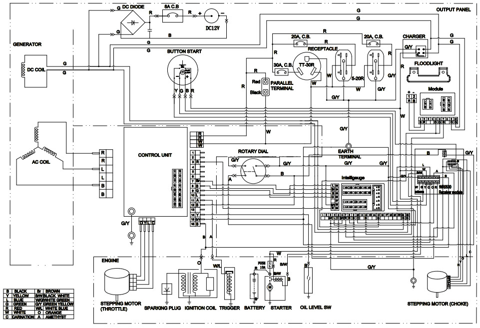
WIRING DIAGRAM
References
[xyz-ips snippet=”download-snippet”]


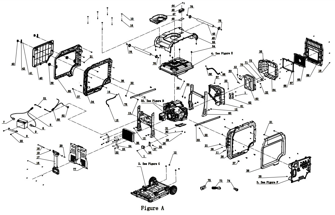
 FIGURE B