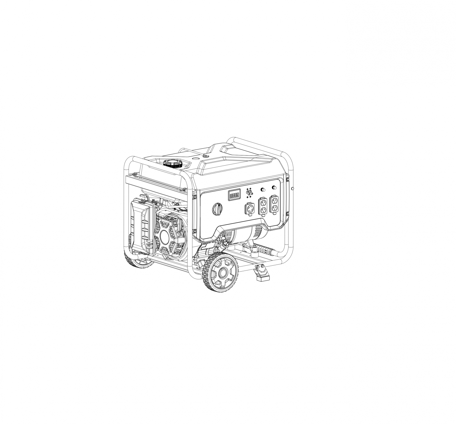
CHAMPION 201073 7000W Portable Generator
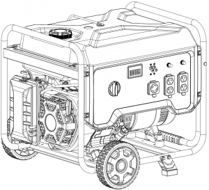
GENERATOR PARTS DIAGRAM
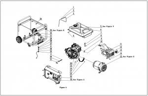
GENERATOR PARTS LIST
|
# |
Part Number |
Description |
Qty. |
|
1 |
2.06.006 | Clamp, Ø7 x Ø1 |
1 |
|
2 |
24.070030.00 | Orifice, Breather Tube |
1 |
|
3 |
152.070014.08 | Tube, Fuel Tank Breather |
1 |
|
4 |
2.06.007 | Clamp Ø8 x b6 |
3 |
|
5 |
152.070000.64.48 | Fuel Tank Assembly, See Figure F |
1 |
|
6 |
2.08.143.1 | Flange Bolt/Washer Assembly M6 x 20, Black |
4 |
|
7 |
45.090006.20 | Bracket, Air Cleaner Support |
1 |
|
8 |
1.6177.1.06 | Lock Nut M6, Flange |
2 |
|
9 |
1.6177.1.08 | Lock Nut M8, Flange |
2 |
|
10 |
46.100001.07 | Gasket, Exhaust |
1 |
|
11 |
46.101000.00.2 | Muffler Assembly |
1 |
|
12 |
1.9074.4.0510 | Screw/Washer Assembly M5 x 10 |
3 |
|
13 |
46.101300.00 | Spark Arrester |
1 |
|
14 |
1.16674.0820.1 | Flange Bolt M8 x 20, Black |
2 |
|
15 |
153.190000.35 | Alternator Assembly, See Figure E |
1 |
|
16 |
1.5789.0608 | Flange Bolt M6 x 8 |
1 |
|
17 |
152.192300.01 | Vent, Alternator Fan |
1 |
|
18 |
152.190005.00 | Rubber, Fore-Cover, A |
1 |
|
19 |
152.190005.01 | Rubber, Fore-Cover, B |
1 |
|
20 |
46.401 | Engine, 389cc |
1 |
|
21 |
152.100007.00 | Heat Shield, Motor Mount |
1 |
|
22 |
1.6177.1.10 | Lock Nut M10, Flange |
4 |
|
23 |
65309.201073 | Frame Assembly, See Figure H |
1 |
|
24 |
2.05.001 | Clamp, Ø8 x 6.5 |
2 |
|
25 |
1.862.06 | Lock Washer Ø6, Toothed |
1 |
|
26 |
5.1900.029 | Grounding Line 150 mm |
1 |
|
27 |
1.97.1.06.2 | Washer Ø6 |
2 |
|
28 |
1.93.06 | Lock Washer Ø6 |
1 |
|
29 |
1.62.06 | Butterfly Type Nut M6 |
1 |
|
30 |
2.05.009 | Clamp Ø12.5 x 7 |
2 |
|
31 |
152.070011.29 | Tube, Fuel, Fuel Valve to Carburetor, 430+20mm |
1 |
|
32 |
1.5789.0615.1 | Flange Bolt M6 x 15, Black |
4 |
|
33 |
201073.21 | Control Panel Assembly, See Figure G |
1 |
ENGINE PARTS DIAGRAM
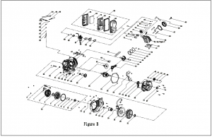
ENGINE PARTS DIAGRAM
|
# |
Part Number | Description |
Qty. |
|
1 |
21.061006.02 | Handle, Recoil, Soft |
1 |
|
2 |
1.5789.0608 | Flange Bolt M6 x 8 |
3 |
|
3 |
46.061100.03.2 | Cover, Recoil Starter, Black |
1 |
|
4 |
45.060005.00 | Spring, Recoil Starter |
1 |
|
5 |
45.061102.00 | Reel, Recoil Starter |
1 |
|
6 |
2.10.003.1 | Rope Ø4 x 1550, Black |
1 |
|
7 |
45.060003.00 | Spring, Ratchet |
2 |
|
8 |
45.060002.00 | Starter Ratchet, Steel |
2 |
|
9 |
45.060009.00 | Spring, Ratchet Guide |
1 |
|
10 |
45.060007.00 | Ratchet Guide |
1 |
|
11 |
45.060008.00 | Screw, Ratchet Guide |
1 |
|
12 |
1.5789.0612 | Flange Bolt M6 x 12 |
12 |
|
13 |
2.05.005 | Clamp Ø6 |
2 |
|
14 |
46.080100.01.48 | Fan Cover, Yellow |
1 |
|
15 |
2.02.007 | Nut M16 x 1.5 |
1 |
|
16 |
1.5789.0629 | Flange Bolt M6 x 29 |
2 |
|
17 |
45.060001.00 | Pulley, Starter |
1 |
|
18 |
46.123000.08 | Ignition Coil |
1 |
|
19 |
45.080001.00 | Fan, Engine |
1 |
|
20 |
46.120100.03 | Flywheel |
1 |
|
21 |
2.11.007 | Oil Seal Ø35 x Ø52 x 8 |
2 |
|
22 |
2.05.050 | Wire Clip, 100 mm |
1 |
|
23 |
152.070031.01 | Sheath, Wire |
1 |
|
24 |
2.03.023 | Washer Ø12.5 x Ø20 x 2, Drain Bolt |
1 |
|
25 |
46.030100.04.1 | Crankcase |
1 |
|
26 |
45.127000.02 | Oil Level Sensor |
1 |
|
27 |
1.5789.0615 | Flange Bolt M6 x 15 |
2 |
|
28 |
1.276.6202 | Bearing 6202 |
2 |
|
29 |
47.050006.00 | Weight Balancer |
1 |
|
30 |
45.050100.14 | Crankshaft |
1 |
|
31 |
46.030008.00 | Gasket, Crankcase Cover |
1 |
|
32 |
2.04.001 | Dowel Pin Ø9 x 14 |
2 |
|
33 |
46.080600.00 | Air Guide, Right Side |
1 |
|
34 |
1.276.6207 | Bearing 6207 |
1 |
|
35 |
46.031000.01.48 | Oil Dipstick, Yellow |
1 |
|
36 |
45.030007.00 | Cover, Crankcase |
1 |
|
37 |
1.5789.0840 | Flange Bolt M8 x 40 |
7 |
|
38 |
2.03.021.1 | Washer Ø6.4 x Ø13 x 1, Black |
1 |
|
39 |
45.110013.00 | Shaft, Governor Gear |
1 |
|
40 |
45.110100.00 | Gear, Governor |
1 |
|
41 |
21.110011.00 | Clip, Governor Gear |
1 |
|
42 |
45.110012.00 | Bushing, Governor Gear |
1 |
|
43 |
47.050200.00 | Connecting Rod |
1 |
|
44 |
46.050005.00 | Piston |
1 |
|
45 |
2.09.004 | Circlip Ø21 x Ø1 |
2 |
|
46 |
45.050003.00 | Pin, Piston |
1 |
|
47 |
46.050303.00 | Ring, Oil |
1 |
|
48 |
46.050302.00 | Ring, Second Piston |
1 |
|
49 |
46.050301.00 | Ring, First Piston |
1 |
|
50 |
2.04.004 | Dowel Pin Ø12 x 20 |
2 |
|
51 |
46.030009.01 | Gasket, Cylinder Head |
1 |
|
52 |
46.080400.00 | Air Guide, Lower |
1 |
|
53 |
46.010000.00 | Cylinder Head Assembly, See Figure C |
1 |
|
54 |
45.110006.00 | Rod, Governor |
1 |
|
55 |
2.15.002(F6RTC) | Spark Plug F6RTC |
1 |
|
56 |
2.08.014 | Flange Bolt M10 x 80 |
4 |
|
57 |
46.020002.00 | Gasket, Cylinder Head Cover |
1 |
|
58 |
46.021000.00 | Cover, Cylinder Head |
1 |
|
59 |
45.020001.02 | Breather Tube |
1 |
|
60 |
45.020100.00 | Bolt, Cylinder Head Cover |
1 |
|
61 |
2.08.039 | Drain Bolt M12 x 1.5 x 15 |
1 |
|
62 |
46.041000.00 | Camshaft |
1 |
|
63 |
45.040013.00 | Lifter, Valve |
2 |
|
64 |
45.110005.00 | Spring, Throttle Return |
1 |
|
65 |
45.110007.00 | Spring, Governor |
1 |
|
66 |
46.040005.00 | Push Rod |
2 |
|
67 |
46.080300.20 | Air Guide, Upper |
1 |
|
68 |
45.040017.00 | Oil Seal, Valve |
2 |
|
69 |
46.091000.09 | Air Cleaner Assembly |
1 |
|
70 |
46.061000.03.2 | Recoil Assembly |
1 |
|
71 |
46.040200.00 | Rocker Arm Assembly |
1 |
|
72 |
1.6177.1.05 | Flange Nut M5 |
6 |
|
73 |
45.040008.00 | Rotator, Exhaust Valve |
1 |
|
74 |
46.040004.00 | Guide Plate, Push Rod |
1 |
|
75 |
46.040016.00 | Shaft, Rocker Arm |
1 |
|
76 |
46.040201.00 | Retainer, Rocker Arm |
1 |
|
77 |
46.040009.00 | Rocker Arm, Intake Valve |
1 |
|
78 |
46.040018.00 | Rocker Arm, Exhaust Valve |
1 |
|
79 |
1.97.1.06 | Washer Ø6 |
2 |
|
80 |
22.040012.00 | Screw, Valve Adjustment |
2 |
|
81 |
1.6177.1.06 | Flange Nut M6 |
2 |
|
82 |
21.040021.00 | Nut M6 x 0.5, Lock |
2 |
|
83 |
21.061301.01.48 | Support, Handle, Recoil |
1 |
|
84 |
46.130002.20 | Gasket, Insulator |
1 |
|
85 |
45.130001.00 | Insulator, Carburetor |
1 |
|
86 |
46.130003.20 | Gasket, Carburetor |
1 |
|
87 |
46.131000.20 | Carburetor Assembly |
1 |
|
46.131000.24 |
|||
|
88 |
46.130004.20 | Gasket, Air Cleaner |
1 |
|
89 |
1.6177.06 | Flange Nut M6 |
3 |
|
90 |
46.091100.09 | Base, Air Cleaner |
1 |
|
91 |
45.091002.20 | Seal, Air Cleaner |
1 |
|
92 |
45.091001.20 | Separator, Air Cleaner |
1 |
|
93 |
45.091003.20 | Element, Air Cleaner |
1 |
|
94 |
46.091200.09 | Cover, Air Cleaner |
1 |
|
95 |
45.110001.00 | Shaft, Governor Arm |
1 |
|
96 |
2.03.019 | Washer Ø8.2 x Ø17 x 0.8 |
1 |
|
97 |
2.11.006 | Oil Seal Ø7 x Ø14 x 5 |
1 |
|
98 |
45.110008.00 | Pin, Shaft |
1 |
|
99 |
45.110003.00 | Arm, Governor |
1 |
|
100 |
2.08.040 | Bolt M6 x 21, Governor Arm |
1 |
CYLINDER HEAD PART DIAGRAM
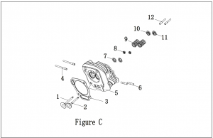
CYLINDER HEAD PART LIST
|
# |
Part Number |
Description |
Qty. |
|
1 |
45.040002.00 | Valve, Intake |
1 |
|
2 |
45.040006.00 | Valve, Exhaust |
1 |
|
3 |
46.030009.01 | Gasket, Cylinder Head |
1 |
|
4 |
2.01.008 | Stud Bolt M6 x M8 x 105 |
2 |
|
5 |
46.010100.00 | Cylinder Head |
1 |
|
6 |
2.01.010 | Stud Bolt M8 x 35 |
2 |
|
7 |
45.040015.00 | Retainer, Valve Spring |
2 |
|
8 |
45.040017.00 | Oil Seal, Valve |
2 |
|
9 |
45.040003.00 | Spring, Valve |
2 |
|
10 |
45.040001.00 | Retainer, Intake Valve Spring |
1 |
|
11 |
45.040007.00 | Retainer, Exhaust Valve Spring |
1 |
|
12 |
23.040010.00 | Bolt, Rocker Arm |
2 |
ALTERNATOR PART DIAGRAM
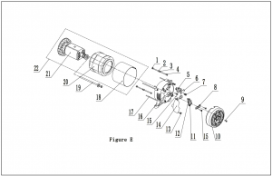
ALTERNATOR PART LIST
| # | Part Number | Description |
Qty. |
|
1 |
1.6175.05 | Nut M5 |
2 |
|
2 |
1.97.1.05 | Washer Ø5 |
2 |
|
3 |
1.93.05 | Lock Washer Ø5 |
2 |
|
4 |
2.08.071 | Bolt M5 x 229 |
2 |
|
5 |
152.190300.00 | Carbon Brush Assembly |
1 |
|
6 |
122.190004.01 | Bracket, Carbon Brush Securing |
1 |
|
7 |
1.9074.15.0520 | Bolt/Washer Assembly M5 x 20 |
1 |
|
8 |
122.190018.03 | Bracket, End Housing Cover |
1 |
|
9 |
2.08.068.1 | Flange Bolt M5 x 13, Black |
1 |
|
10 |
152.190003.02.48 | Cover, End Housing, Yellow |
1 |
|
11 |
1.9074.17.0516 | Screw/Washer Assembly M5 x 16 |
2 |
|
12 |
122.190400.02 | Terminal Block |
1 |
|
13 |
1.16674.0516 | Flange Bolt M5 x 16 |
2 |
|
14 |
153.190200.03 | AVR |
1 |
|
15 |
1.16674.0512 | Flange Bolt M5 x 12 |
3 |
|
16 |
152.190002.00 | End Housing |
1 |
|
17 |
2.08.069 | Flange Bolt/Washer Assembly M6 x 194 |
4 |
|
18 |
153.191002.00 | Stator Cover |
1 |
|
19 |
2.08.070 | Flange Bolt/Washer Assembly M10 x 280 |
1 |
|
20 |
153.191200.35 | Stator Assembly, Al, Ø190 x 148 mm, DC 12V |
1 |
|
21 |
153.191100.18 | Rotor Assembly, Al, Ø190x 158 mm, DC 12V |
1 |
|
22 |
153.191000.35 | Alternator Assembly, Al, Ø190 x 158 mm, DC 12V |
1 |
FUEL TANK PART DIAGRAM
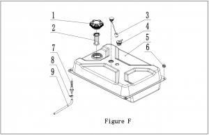
FUEL TANK PART LIST
| # | Part Number |
Description |
Qty. |
|
1 |
122.070100.09 | Fuel Tank Cap |
1 |
|
2 |
122.070300.03 | Fuel Filter |
1 |
|
3 |
152.072000.06 | Fuel Gauge |
1 |
|
4 |
24.070800.00 | Reversal Valve |
1 |
|
5 |
152.071000.64.48 | Fuel Tank, 29.1L, Yellow |
1 |
|
6 |
122.070015.01 | Mount Vibration, Fuel Tank |
4 |
|
7 |
21.070600.03 | Fitting, Fuel Tank |
1 |
|
8 |
2.06.016 | Clamp Ø8.7 x b8 |
1 |
|
9 |
152.070011.30 | Tube, Fuel, 245+32 mm, Fuel Tank to Fuel Valve |
1 |
CONTROL PANEL PART DIAGRAM
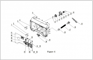
CONTROL PANEL PART LIST
|
# |
Part Number |
Description |
Qty. |
|
1 |
5.1810.000 | VFO Diode |
1 |
|
2 |
1.818.0514.2 | Screw M5 x 14 |
2 |
|
3 |
5.1800.000 | Rectifier |
1 |
|
4 |
152.210002.63 | Control Panel Housing |
1 |
|
5 |
1.6177.1.05 | Lock Nut M5, Flange, Black |
8 |
|
6 |
62.139002.00.48 | Cover, Fuel Select Dial, Yellow |
1 |
|
7 |
1.9074.4.0414.1 | Screw/Washer Assembly M4 x 14, Black |
1 |
|
8 |
122.139001.01 | Fuel Select Dial |
1 |
|
9 |
1.845.0.2216 | Screw, ST2.2 x 16 |
2 |
|
10 |
5.1050.006 | Microswitch, 2-Pole |
1 |
|
11 |
122.139004.01 | Mounting Plate, Fuel Valve |
1 |
|
12 |
1.845.4816 | Screw, ST4.8 x 16 |
4 |
|
13 |
62.070400.00 | Fuel Valve |
1 |
|
14 |
1.818.0410 | Screw M4 x 10 |
2 |
|
15 |
201073.21.10 | Wire Assembly |
1 |
|
16 |
152.210003.03 | Plug, End Housing |
1 |
|
17 |
5.1320.024 | Sheath, Wire |
1 |
|
18 |
152.210003.01 | Wire Jacket, Control Panel Housing |
1 |
|
19 |
5.1830.022 | Module, CO Shutdown |
1 |
|
20 |
1.845.4213 | Screw, ST4.2 x 13 |
2 |
|
21 |
5.1210.920 | 20Amp Circuit Breaker, Push Button, CSA |
2 |
|
22 |
5.1870.014 | Circuit Breaker Cover, Push Button |
2 |
|
23 |
5.1240.929 | 29Amp Circuit Breaker, Double Pole |
1 |
|
24 |
5.1120.050 | Receptacle 5-20R, Duplex GFCI |
2 |
|
25 |
1.6177.1.04.1 | Lock Nut M4, Flange, Black |
6 |
|
26 |
5.1870.022 | Receptacle Cover, Receptacle 5-20R, Duplex GFCI |
2 |
|
27 |
1.9074.4.0306.1 | Screw/Washer Assembly M3 x 6, Black |
4 |
|
28 |
5.1120.026 | Receptacle L14-30R, CSA |
1 |
|
29 |
5.1870.020 | Receptacle Cover, Receptacle L14-30R |
1 |
|
30 |
5.1470.000 | Intelligauge, INT1AOF |
1 |
|
31 |
152.25.5.2 | Control Panel |
1 |
FRAME PART DIAGRAM
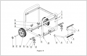
FRAME PART LIST
| # | Part Number |
Description |
Qty. |
|
1 |
65309.0.10.2 | Frame, 680 x 556 x 567 |
1 |
|
2 |
152.200703.05 | Long Pin, Handle |
2 |
|
3 |
11.110008.00 | Pin Ø1.6 x 24, “R” Shape , Black |
2 |
|
4 |
122.200702.14.48 | Cover, Handle, Lower, Yellow |
1 |
|
5 |
122.200702.13.48 | Cover, Handle, Upper, Yellow |
1 |
|
6 |
1.9074.4.0414.1 | Screw/Washer Assembly M4 x 14, Black |
2 |
|
7 |
152.200701.22.2 | Handle, U Shape, Black |
1 |
|
8 |
152.200703.02 | Short Pin, Handle |
2 |
|
9 |
1.894.1.08 | Circlip Ø8 |
2 |
|
10 |
1.6177.1.08 | Lock Nut M8, Flange |
4 |
|
11 |
1.6177.1.08.1 | Lock Nut M8, Flange , Black |
6 |
|
12 |
1.5789.0825.1 | Flange Bolt M8 x 25, Black |
2 |
|
13 |
122.201400.04 | Rubber, Support, 55 x 36 x 22 |
2 |
|
14 |
152.200002.16.2 | Support Leg, 68 mm, Black |
2 |
|
15 |
1.5789.0840.1 | Flange Bolt M8 x 40, Black |
4 |
|
16 |
122.201701.11.48 | 8 in. Wheel, PU, Yellow |
2 |
|
17 |
122.201501.23.1 | Pin Roll, Wheel, Ø16 x Ø10 x 97, Black |
2 |
|
18 |
122.201702.11.48 | Wheel Cover, Tooth Profile 8-10 in, Yellow |
2 |
|
19 |
2.16.001.1 | Pin Ø2 x 33, “R” Shape , Black |
2 |
|
20 |
152.201200.03 | Motor Mount 1 |
2 |
|
21 |
152.201200.04 | Motor Mount 2 |
2 |
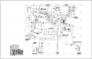
WIRING DIAGRAM
 |
To order replacement parts please visit:shop.championpowerequipment.comor call 1-877-338-0999. |

www.championpowerequipment.com
References
[xyz-ips snippet=”download-snippet”]