![]() Model #201076
Model #201076
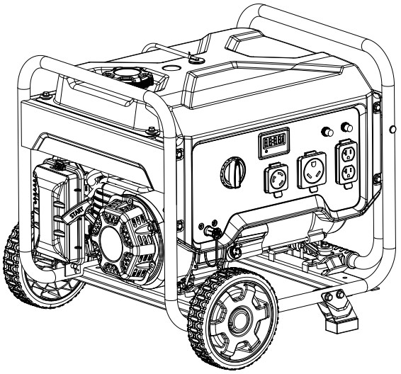
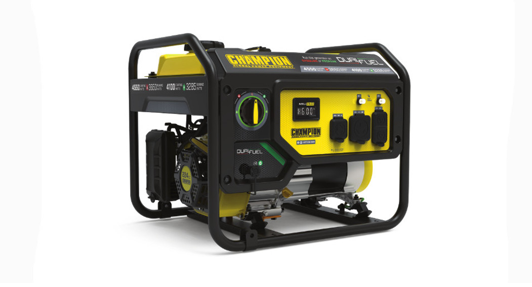
PARTS INFORMATION3650W DuAl Fuel PORTAble GeNeRATORSeRIAl NuMbeR RANGe: All
 To order replacement parts please visit:shop.championpowerequipment.comor call 1-877-338-0999.
GENERATOR PARTS DIAGRAM
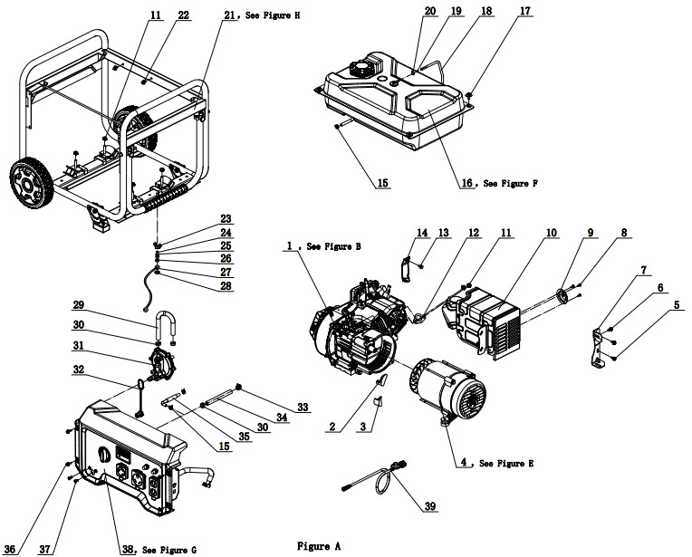
GENERATOR PARTS lIST
| # | Part Number | Description | Oty. |
| 1 | 27.696.48 | Engine, 224cc, See Figure B | 1 |
| 2 | 122.190005.00 | Rubber, Fore-Cover, B | 1 |
| 3 | 122.190005.01 | Rubber, Fore-Cover, A | 1 |
| 4 | 124.190000.23 | Alternator Assembly, Al, 0160 x 130 mm, CSA, See Figure E | 1 |
| 5 | 1.5789.0620 | Flange Bolt M6 x 20 | 2 |
| 6 | 1.5789.0615 | Flange Bolt M6 x 15 | 1 |
| 7 | 27.100100.01 | Bracket, Muffler | 1 |
| 8 | 1.823.0406 | Screw M4 x 6 | 3 |
| 9 | 27.101300.00 | Spark Arrester | 1 |
| 10 | 27.101000.04.2 | Muffler Assembly | 1 |
| 11 | 1.6177.1.08 | Lock Nut M8, Flange | 6 |
| 12 | 26.100001.00 | Gasket, Exhaust | 1 |
| 13 | 1.5789.0608 | Flange Bolt M6 x 8 | 1 |
| 14 | 23.090006.21 | Bracket, Air Cleaner Support | 1 |
| 15 | 2/6/1916 | Clamp 08.8 x b8 | 3 |
| 16 | 122.070000.66 | Fuel Tank Assembly, See Figure F | 1 |
| 17 | 2.08.143.1 | Flange Bolt/Washer Assembly M6 x 20, Black | 4 |
| 18 | 122.070014.02 | Tube, Fuel Tank Breather, 670 mm | 1 |
| 19 | 24.070030.00 | Orifice, Breather Tube | 1 |
| 20 | 2/6/1906 | Clamp 07 x 01 | 1 |
| 21 | 62405. | Frame Assembly, See Figure H | 1 |
| 22 | 2/5/1901 | Clamp 08 x 6.5 | 2 |
| 23 | 1.62.06 | Butterfly Type Nut M6 | 1 |
| 24 | 1.93.06.2 | Lock Waher 06 | 1 |
| 25 | 1.97.1.06.2 | Washer 06 | 2 |
| 26 | 1.6177.1.06 | Lock Nut M6, Flange | 1 |
| 27 | 5.1900.029 | Grounding Line 150 mm | 1 |
| 28 | 1.862.06 | Lock Washer 06, Toothed | 1 |
| 29 | 152.070012.13 | Hose, LPG, 200 mm | 1 |
| 30 | 2/6/1932 | Clip 017 | 3 |
| 31 | 27.136000.02 | Pressure-Reducing Valve | 1 |
| 32 | 9.1500.005 | Cover, LPG Connector | 1 |
| 33 | 2/6/1923 | Clip 020 | 1 |
| 34 | 152.070012.12 | Hose, LPG, 325 mm | 1 |
| 35 | 122.070011.14 | Tube, Fuel 380+25 mm, Fuel Tank to Fuel Valve | 1 |
| 36 | 1.5789.0615.1 | Flange Bolt M6 x 15, Black | 4 |
| 37 | 1.818.0614.1 | Bolt M6 x 14, Black | 2 |
| 38 | 201070. | Control Panel Assembly | 1 |
| 39 | 122.070012.12 | LPG Hose With Regulator 6.5 ft. | 1 |
ENGINE PARTS DIAGRAM
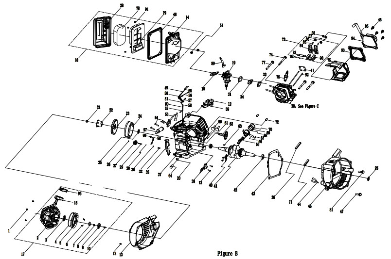
ENGINE PARTS PART lIST
| # | Part Number | Description | City. |
| 1 | 1.16674.0608 | Flange Bolt M6 x 8 | 3 |
| 2 | 27.061100.01.2 | Cover, Recoil Starter, Black | 1 |
| 3 | 21.061005.00 | Recoil Starter Spring | 1 |
| 4 | 2.10.003.1 | Rope 04 x 1550, Black | 1 |
| 5 | 21.061001.01 | Reel, Recoil Starter | 1 |
| 6 | 45.060003.00 | Spring, Ratchet | 2 |
| 7 | 45.060002.00 | Starter Ratchet, Steel | 2 |
| 8 | 45.060009.00 | Spring, Ratchet Guide | 1 |
| 9 | 45.060007.00 | Ratchet Guide | 1 |
| 10 | 45.060008.00 | Screw, Ratchet Guide | 1 |
| 11 | 24.040004.00 | Guide Plate, Push Rod | 1 |
| 12 | 1.5789.0612 | Flange Bolt M6 x 12 | 8 |
| 13 | 27.080100.07.48 | Fan Cover, Yellow | 1 |
| 14 | 24.091100.21 | Base, Air Cleaner | 1 |
| 15 | 21.061006.02 | Handle, Recoil, Soft | 1 |
| 16 | 24.130004.20 | Gasket, Air Cleaner | 1 |
| 17 | 27.061000.01 | Recoil Assembly | 1 |
| 18 | 27.091000.04 | Air Cleaner Assembly | 1 |
| 19 | 27.131000.00 | Carburetor Assembly, See Figure D | 1 |
| 20 | 2/3/1916 | Washer 010 x 016 x 1.5, Drain Bolt | 1 |
| 21 | 2/2/1906 | Nut M14 x 1.5 | 1 |
| 22 | 23.060001.01 | Pulley, Starter | 1 |
| 23 | 27.080001.00 | Fan, Engine | 1 |
| 24 | 24.120100.11 | Flywheel | 1 |
| 25 | 211. | Oil Seal 025 x 041.3 x 6 | 2 |
| 26 | 2.03.020.1 | Washer 06.2 x 015 x 0.5, Black | 2 |
| 27 | 21.110100.00 | Gear, Governor | 1 |
| 28 | 27.091200.04 | Cover, Air Cleaner | 1 |
| 29 | 21.110013.00 | Shaft, Governor Gear | 1 |
| 30 | 21.110011.00 | The clip, Governor Gear | 1 |
| 31 | 22.130003.00 | Gasket, Carburetor | 1 |
| 32 | 21.110012.01 | Bushing, Governor Gear, Steel | 1 |
| 33 | 24.130002.00 | Gasket, Insulator | 1 |
| 34 | 27.130001.00 | Insulator, Carburetor | 1 |
| 35 | 23.080600.01 | Air Guide, Right Side | 1 |
| 36 | 27.030013.00 | Seal Strip, Crankcase Cover, Long | 1 |
| 37 | 27.030100.01 | Crankcase | 1 |
| 38 | 21.127000.02 | Oil Level Sensor | 1 |
| 39 | 27.010000.00 | Cylinder Head Assembly,See Figure C | 1 |
| 40 | 27.050200.00 | Connecting Rod Assembly | 1 |
| 41 | 27.050100.00 | Crankshaft | 1 |
| 42 | 1.276.6205 | Bearing 6205 | 2 |
| 43 | 24.030008.00 | Gasket, Crankcase Cover | 1 |
| 44 | 22.031000.00.48 | Oil Dipstick Assembly, Yellow | 1 |
| 45 | 1.5789.0615 | Flange Bolt M6 x 15 | 4 |
| 46 | 27.030007.01 | Cover, Crankcase | 1 |
| 47 | 1.5789.0832 | Flange Bolt M8 x 32 | 5 |
| 48 | 23.091002.21 | Seal, Air Cleaner | 1 |
| 49 | 23.110006.00 | Rod, Governor | 1 |
| 50 | 27.110003.00 | Arm, Governor | 1 |
| 51 | 1.6177.06 | Flange Nut M6 | 3 |
| 52 | 21.110001.00 | Shaft, Governor Arm | 1 |
| 53 | 22.123000.05 | Ignition Coil | 1 |
| 54 | 1.5789.0625 | Flange Bolt M6 x 25 | 4 |
| 55 | 23.110005.01 | Spring, Throttle Return | 1 |
| 56 | 27.110007.00 | Spring, Governor | 1 |
| 57 | 2/8/1940 | Bolt M6 x 21, Governor Arm | 1 |
| 58 | 21.110008.00 | Pin, Shaft | 1 |
| 59 | 27.111000.20 | HSNL Control Assembly | 1 |
| 60 | 25.040013.00 | Lifter, Valve | 2 |
| 61 | 2/4/1901 | Dowel Pin, 09 x 14 | 2 |
| 62 | 27.041000.01 | Camshaft | 1 |
| 63 | 2/14/1912 | Woodruff Key, 4 x 7.5 x 19 | 1 |
| 64 | 2/8/1937 | Drain Bolt M10 x 1.25 x 25 | 1 |
| 65 | 27.050005.00 | Piston | 1 |
| 66 | 23.050003.00 | Pin, Piston | 1 |
| 67 | 2/9/1901 | Circlip 018 x 01 | 2 |
| 68 | 27.050303.00 | Ring, Oil | 1 |
| 69 | 27.050302.00 | Ring, Second Piston | 1 |
| 70 | 27.050301.00 | Ring, First Piston | 1 |
| 71 | 27.030013.01 | Seal Strip, Crankcase Cover, Short | 1 |
| 72 | 2/4/1903 | Dowel Pin 010 x 14 | 2 |
| 73 | 24.040200.00 | Rocker Arm Assembly | 1 |
| 74 | 2.08.121 | Flange Bolt M10 x 65 | 1 |
| 75 | 27.080200.00 | Air Shroud, Cylinder | 1 |
| 76 | 2.15.002(F6RTC) | Spark Plug F6RTC | 1 |
| 77 | 1.5789.0865 | Flange Bolt M8 x 65 | 3 |
| 78 | 23.091003.21 | Element, Air Cleaner | 1 |
| 79 | 23.091001.21 | Separator, Air Cleaner | 1 |
| 80 | 2.03.021.1 | Washer 06.4 x 013 x 1, Black | 1 |
| 81 | 1.5789.0840 | Flange Bolt M8 x 40 | 1 |
| 82 | 21.040008.00 | Rotator, Exhaust Valve | 1 |
| 83 | 24.040202.00 | Shaft, Rocker Arm | 1 |
| 84 | 22.040009.00 | Rocker Arm | 2 |
| 85 | 22.040012.00 | Screw, Valve Adjustment | 2 |
| 86 | 21.040021.00 | Nut M6 x 0.5, Lock | 2 |
| 87 | 1.97.1.06 | Washer 06 | 2 |
| 88 | 1.6177.1.06 | Flange Lock Nut M6 | 2 |
| 89 | 27.131001.13 | Choke Lever | 1 |
| 90 | 24.040201.00 | Retainer, Rocker Arm | 1 |
| 91 | 2.08.166 | Flange Bolt M5x12 | 4 |
| 92 | 27.040005.00 | Push Rod | 2 |
| 93 | 21.020002.01 | Gasket, Cylinder Head Cover | 1 |
| 94 | 24.021000.00 | Cover, Cylinder Head | 1 |
| 95 | 23.020001.02 | Tube, Breather, 112+35 | 1 |
| 96 | 21.061301.01.48 | Insert, Handle, Recoil | 1 |
| 97 | 45.121000.00 | Coil, Charging | 1 |
| 98 | 23.030006.00 | Plate, Coil | 1 |
| 99 | 1.5789.0608 | Flange Bolt M6 x 8 | 1 |
CYlINDeR PART DIAGRAM
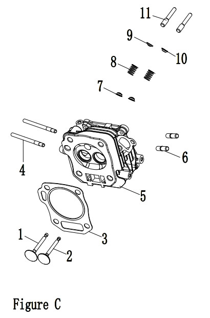
CYlINDeR PART lIST
| # | Part Number | Description | Qty. |
| 1 | 23.040002.02 | Valve, Intake | 1 |
| 2 | 27.040006.00 | Valve, Exhaust | 1 |
| 3 | 27.030009.01 | Gasket, Cylinder Head | 1 |
| 4 | 2/1/1903 | Stud Bolt M6 x 90 | 2 |
| 5 | 26.010100.01 | Cylinder Head, 224cc | 1 |
| 6 | 2/1/1910 | Stud Bolt M8 x 35 | 2 |
| 7 | 23.040017.00 | Oil Seal, Valve, Steel | 2 |
| 8 | 21.040003.00 | Spring, Valve | 2 |
| 9 | 21.040001.00 | Retainer, Intake Valve Spring | 1 |
| 10 | 21.040007.00 | Retainer, Exhaust Valve Spring | 1 |
| 11 | 23.040010.00 | Bolt, Rocker Arm | 2 |
AlTeRNATOR PART DIAGRAM

AlTERNATOR PART LIST
| # | Part Number | Description | Qty. |
| 1 | 124.191200.23 | Alternator Assembly, Al, 0160 x 130 mm, CSA | 1 |
| 2 | 124.191100.02 | Rotor Assembly, Al, 0160 x 130 mm, CSA | 1 |
| 3 | 2.08.109 | Flange Bolt/Washer Assembly M8 x 252 | 1 |
| 4 | 124.191200.06 | Stator Assembly, Al, 0160 x 130 mm, CSA | 1 |
| 5 | 124.191002.01 | Stator Cover | 1 |
| 6 | 2/8/1932 | Flange Bolt/Washer Assembly M6 x 179 | |
| 7 | 122.190002.00 | End Housing | 1 |
| 8 | 1.16674.0512.2 | Flange Bolt M5 x 12 | 3 |
| 9 | 122.190300.00 | Carbon Brush Assembly | 1 |
| 10 | 122.190004.01 | Bracket, Carbon Brush Holding | 1 |
| 11 | 1.9074.15.0520 | Bolt/Washer Assembly M5 x 20 | 1 |
| 12 | 122.190400.02 | Terminal Block | 1 |
| 13 | 1.9074.17.0516 | Screw/Washer Assembly M5 x 16 | 2 |
| 14 | 122.190200.03 | AVR | 1 |
| 15 | 1.16674.0516 | Flange Bolt M5 x 16 | 2 |
| 16 | 122.190018.03 | Bracket, End Housing Cover | 1 |
| 17 | 122.190003.01.48 | Cover, End Housing, Yellow | 1 |
| 18 | 2.08.068.1 | Flange Bolt M5 x 13, Black | 1 |
Fuel TANK PART DIAGRAM
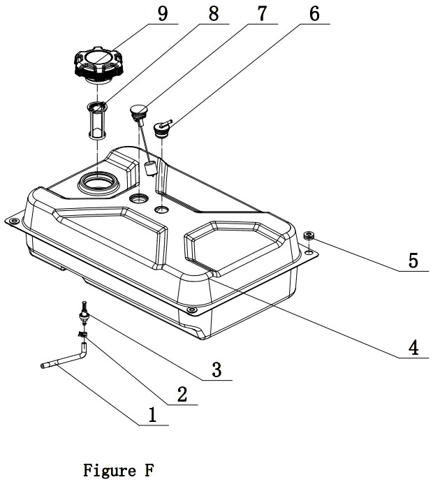
FUEl TANK PART lIST
| # | Part Number | Description | Qty. |
| 1 | 122.070011.19 | Tube, Fuel, 25+250+25 mm, Fuel Tank to Fuel Valve | 1 |
| 2 | 2/6/1916 | Clamp 08.8 x b8 | 1 |
| 3 | 21.070600.03 | Fitting, Fuel Tank | 1 |
| 4 | 122.071000.66.48 | Fuel Tank, 18L, Yellow | 1 |
| 5 | 122.070015.01 | Mount Vibration, Fuel Tank | 2 |
| 6 | 24.070800.00 | Reversal Valve | 1 |
| 7 | 122.072000.03 | Fuel Gauge | 1 |
| 8 | 122.070300.03 | Fuel Filter | 1 |
| 9 | 122.070100.09 | Fuel Tank Cap | 1 |
CONTROl PANel PART DIAGRAM
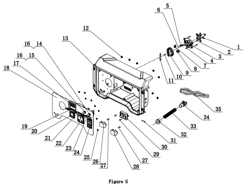
CONTROL PANEL PART LIST
| # | Part Number | Description | Oty. |
| 1 | 122.070400.09 | Valve, Dual Fuel Select | 1 |
| 2 | 1.845.4816 | Screw, ST4.8 x 16 | 4 |
| 3 | 122.139004.02 | Plate, Fuel Dial Mounting | 1 |
| 4 | 1.818.0414.1 | Screw M4 x 14, Black | 3 |
| 5 | 62.139007.00 | Spring, Steel Ball | 1 |
| 6 | 1.308.7 | Ball Bearing, Rotary Knob | 1 |
| 7 | 5.1050.005 | Microswitch, 1-Pole | 1 |
| 8 | 5.1050.006 | Microswitch, 2-Pole | 1 |
| 9 | 122.139001.02 | Rotary Knob | 1 |
| 10 | 1.9074.4.0414.1 | Screw/Washer Assembly M4 x 14, Black | 1 |
| 11 | 62.139002.00.48 | Cover, Rotary Knob, Yellow | 1 |
| 12 | 1.6177.1.05 | Lock Nut M5, Flange | 7 |
| 13 | 122.210002.64 | Control Panel Housing | 1 |
| 14 | 5.1210.920 | 20Amp Circuit Breaker, Push Button, CSA | 1 |
| 15 | 5.1210.930 | 30Amp Circuit Breaker, Push Button, CSA | 1 |
| 16 | 5.1870.014 | Circuit Breaker Cover, Push Button | 2 |
| 17 | 5.1470.000 | Intelligauge, INT1AOF | 1 |
| 18 | 122.25.5.2 | Control Panel | 1 |
| 19 | 5.1870.023 | Receptacle Cover, Receptacle L5-30R | 1 |
| 20 | 5.1120.023 | Receptacle L5-30R, CSA | 1 |
| 21 | 5.1870.021 | Receptacle Cover, Receptacle TT-30R | 1 |
| 22 | 5.1120.036 | Receptacle TT-30R | 1 |
| 23 | 5.1870.025 | Receptacle Cover, Receptacle 5-20R | 1 |
| 24 | 5.1120.027 | Receptacle 5-20R, Duplex, CSA | 1 |
| 25 | 1.6177.1.04.1 | Lock Nut M4, Flange, Black | 8 |
| 26 | 5.1820.004 | Charger Module | 1 |
| 27 | 1.818.0514.2 | Screw M5 x 14 | 2 |
| 28 | 5.1810.004 | Over Voltage Protector, CSA | 1 |
| 29 | 1.845.4216 | Screw, ST4.2 x 16 | 2 |
| 30 | 5.1830.022 | CO Module | 1 |
| 31 | 5.1280.008 | Fuse 5A | 1 |
| 32 | 122.210003.02 | Wire Jacket, Control Box Housing, CSA | 1 |
| 33 | 5.1320.012 | Sheath, Wire, CSA | 1 |
| 34 | 122.210003.04 | Plug, End Cover, CSA | 1 |
| 35 | 201076.21.10 | Wire Harness Assembly | 1 |
FRAMe ASSeMblY PART DIAGRAM
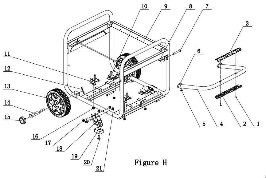
FRAME ASSEMblY PART lIST
| # | Part Number | Description | Qty. |
| 1 | 1.9074.4.0414.1 | Screw/Washer Assembly M4 x 14, Black | 2 |
| 2 | 122.200702.13 | Cover, Handle, Upper | 1 |
| 3 | 122.200702.14 | Cover, Handle, Lower | 1 |
| 4 | 122.200701.13 | Handle, U Style | 1 |
| 5 | 1.894.1.08 | Circlip 08 | 2 |
| 6 | 152.200703.02 | Short Pin. Handle | 2 |
| 7 | 152.200703.05 | Long Pin, Handle | 2 |
| 8 | 11.110008.00 | “R” Shape | 2 |
| 9 | 62405.09.16.2 | Frame, 590 x 492 x 502mm | 1 |
| 10 | 122.201200.07 | Motor Mount 2 | 2 |
| 11 | 122.201200.06 | Motor Mount 1 | 2 |
| 12 | 2.16.001.1 | Pin 02 x 33, “R” Shape. Blcak | 2 |
| 13 | 122.201701.11.48 | 8 in. Wheel. PU, Yellow | 2 |
| 14 | 122.201501.23.1 | Pin Roll, Wheel, 016 x 010 x 97, Black | 2 |
| 15 | 122.201702.11.48 | Wheel Cover, Tooth Profile 8-10 in. Yellow | 2 |
| 16 | 1.6177.1.08 | Lock Nut M8. Flange | 4 |
| 17 | 1.5789.0840.1 | Flange Bolt M8 x 40, Blcak | 4 |
| 18 | 152.200002.16.2 | Support Leg. 68 mm | 2 |
| 19 | 122.201400.04 | Rubber, Support | 2 |
| 20 | 1.5789.0825.1 | Flange Bolt M8 x 25, Blcak | 2 |
| 21 | 1.6177.1.08.1 | Lock Nut M8. Flange, Black | 6 |
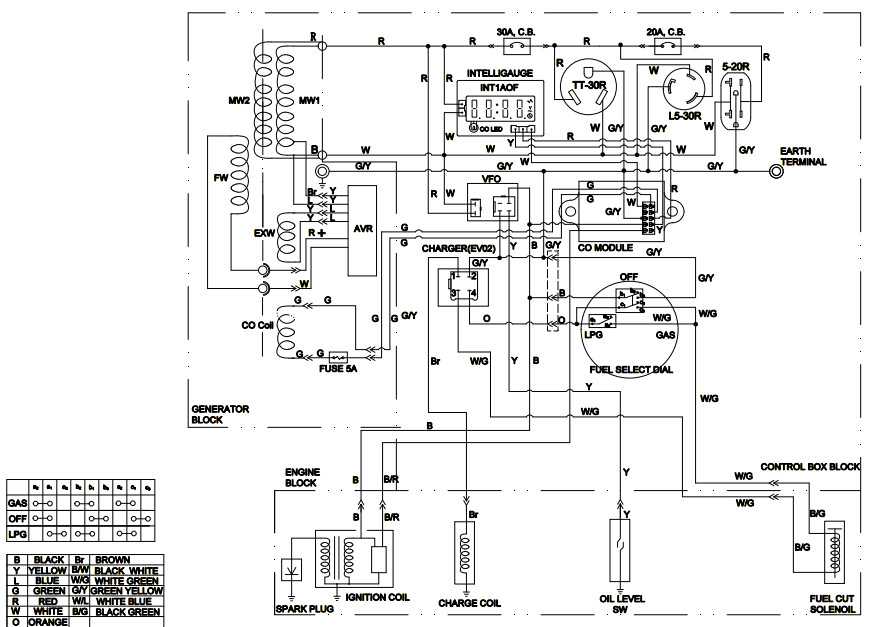
WIRING DIAGRAM
References
[xyz-ips snippet=”download-snippet”]