
User Manual
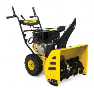
Champion 24 In. 2-Stage Snowblower – 100679
REGISTER YOUR PRODUCT ONLINE at championpowerequipment.com
READ AND SAVE THIS MANUAL. This manual contains important safety precautions which should be read and understood before operating the product. Failure to do so could result in serious injury. This manual should remain with the product. Specifications, descriptions and illustrations in this manual are as accurate as known at the time of publication, but are subject to change without notice.
Champion Power Equipment, Inc., Santa Fe Springs, CA USA
INTRODUCTION
Congratulations on your purchase of a Champion Power Equipment (CPE) product. CPE designs, builds, and supports all of our products to strict specifications and guidelines. With proper product knowledge, safe use, and regular maintenance, this product should bring years of satisfying service.
Every effort has been made to ensure the accuracy and completeness of the information in this manual at the time of publication, and we reserve the right to change, alter and/or improve the product and this document at any time without prior notice.
Since CPE highly values how our products are designed, manufactured, operated and are serviced, and also highly value your safety and the safety of others, we would like you to take the time to review this product manual and other product materials thoroughly and be fully aware and knowledgeable of the assembly, operation, dangers and maintenance of the product before use. Fully familiarize yourself, and make sure others who plan on operating the product fully familiarize themselves too, with the proper safety and operation procedures before each use. Please always exercise common sense and always err on the side of caution when operating the product to ensure no accident, property damage, or injury occurs. We want you to continue to use and be satisfied with your CPE product for years to come.
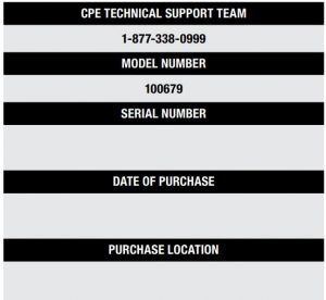
When contacting CPE about parts and/or service, you will need to supply the complete model and serial numbers of your product. Transcribe the information found on your product’s nameplate label to the table below
IMPORTANT SAFETY INSTRUCTIONS
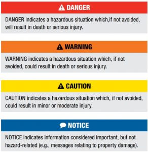
SAFETY DEFINITIONSThe purpose of safety symbols is to attract your attention to possible dangers. The safety symbols, and their explanations, deserve your careful attention and understanding. The safety warnings do not by themselves eliminate any danger. The instructions or warnings they give are not substitutes for proper accident prevention measures.
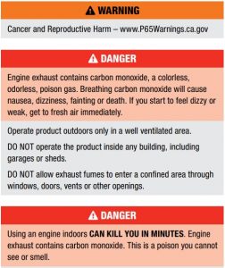
NEVER use inside a home or garage, EVEN IF doors and windows are open.ONLY use OUTSIDE and far away from windows, doors, and vents.
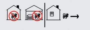
Install battery-operated carbon monoxide alarms or plug-in carbon monoxide alarms with battery back-up according to the manufacturer’s instructions.
![]() DANGER
DANGER
Rotating parts can entangle hands, feet, hair, clothing and/or accessories. Traumatic amputation or severe laceration can result.Keep hands and feet away from rotating parts.Tie up long hair and remove jewelry.Operate equipment with guards in place.DO NOT wear loose-fitting clothing, dangling drawstrings or items that could become caught.
![]() WARNING
WARNING
Sparks can result in fire or electrical shock.When servicing the engine:Disconnect the spark plug wire and place it where it cannot contact the plug.DO NOT check for spark with the plug removed.Use only approved spark plug testers.
![]() WARNING
WARNING
Running engines produce heat. Severe burns can occur on contact. Combustible material can catch fire on contact.DO NOT touch hot surfaces.Avoid contact with hot exhaust gases.Allow equipment to cool before touching.
Fuel Safety
![]() DANGER
DANGER
GASOLINE AND GASOLINE VAPORS ARE HIGHLY FLAMM ABLE AND EXPLOSIVE.Fire or explosion can cause severe burns or death.
Gasoline and gasoline vapors:
- Gasoline is highly flammable and explosive.
- Gasoline can cause a fire or explosion if ignited.
- Gasoline is a liquid fuel but it’s vapors can ignite.
- Gasoline is a skin irritant and needs to be cleaned up immediately if spilled on skin or clothes.
- Gasoline has a distinctive odor, this will help detect potential leaks quickly.
- Gasoline expands or contracts with ambient temperatures. Never fill the gasoline tank to full capacity, as gasoline needs room to expand when temperatures rise.
- In the case of any petroleum gasoline fire, flames should never be extinguished unless the fuel supply valve can be turned OFF. By not doing so, if a fire is extinguished and the supply of fuel is not turned OFF, an explosion hazard could be created.
When adding or removing gasoline:
- DO NOT light or smoke cigarettes.
- Turn the snowblower off and let cool for a minimum of two minutes before removing the gasoline cap. Loosen gasoline cap to relieve pressure from the gasoline tank.
- Only fill or drain gasoline outdoors in a well-ventilated area.
- DO NOT pump gasoline directly into the snowblower at the gas station. Always use an approved fuel container to transfer the gasoline to the snowblower.
- DO NOT overfill the gasoline tank. Keep fuel level at least 1/2 inch below bottom of filler neck to provide space for fuel expansion.
- Never remove gas cap or add fuel while the engine is hot or running.
- When gasoline spills, wipe the fuel off the engine and equipment. Move the snowblower from fuel spill area to another area.
- Wait 5 minutes before starting the engine.
- Always keep gasoline away from sparks, open flames, pilot lights, heat and other sources of ignition.
When starting the engine:
- DO NOT attempt to start a damaged snowblower.
- Always make certain that the gasoline cap, air filter, spark plug, fuel lines and exhaust system are properly secured, connected and in place.
- Always allow spilled gasoline to evaporate fully before attempting to start the engine.
- Make certain that the snowblower is resting firmly on level ground.
When operating the snowblower:
- DO NOT tip the snowblower during operation.
- DO NOT tip the snowblower or allow fuel or oil to spill.
When transporting or servicing the snowblower:
- Make certain that the fuel valve is in the OFF position and the gasoline tank is empty.
- Disconnect the spark plug wire.
When storing the snowblower:
- Store away from sparks, open flames, pilot lights, heat and other sources of ignition.
- Do not store the snowblower or gasoline near furnaces, water heaters, or any other appliances that produce heat or have automatic ignitions.
![]() WARNING
WARNING
Never use a gasoline container, gasoline tank, or any other fuel item that is broken, cut, torn or damaged.
Training
- Read the Operator’s Manual completely before attempting to use the snowblower. Be thoroughly familiar with the controls and the proper use of the equipment. Know how to stop the engine and disengage the controls quickly.
- Never allow children under 16 years old to operate the equipment. Never allow adults to operate the equipment without proper instruction.
- Thrown objects can cause serious injury. Keep the area of operation clear of all persons, particularly small children, and pets. Plan your snow discharge pattern to prevent throwing material toward cars, structures, roads and people.
- Exercise caution to avoid slipping or falling, especially when operating in reverse.
- Be aware that the operator or user is responsible for accidents or hazards occurring to other people or their property.
- Never use the snowblower under the influence of alcohol or medication, or if you are tired or ill.
Preparation For Use
- Be thoroughly familiar with the controls and the proper use of the equipment. Understand and know how to stop the engine and disengage the controls quickly.
- Thoroughly inspect the area where the equipment is to be used and remove all doormats, sleds, boards, wires, and other foreign objects.
- Disengage all clutch handles before starting the motor.
- Do not operate the equipment without wearing adequate winter garments. Wear footwear which will improve footing on slippery surfaces.
- Adjust the auger housing height to clear gravel or crushed rock surface.
- Never attempt to make any adjustments while the engine is running (except where specifically recommended in the manual).
- Let engine and machine adjust to outdoor temperatures before starting to clear snow.
- The operation of any powered machine can result in foreign objects being thrown into the eyes. Always wear eye protection with side shields marked to comply with ANSI Z87.1 during operation, or while performing an adjustment or repair.
- Inspect the auger and impeller before starting to ensure that there is no ice build up.
Operation
- Do not put hands or feet near or under rotating parts. Keep clear of the discharge opening at all times.
- Exercise extreme caution when operating on or crossing gravel drives, walks, or roads. Stay alert for hidden hazards or traffic.
- In the event of striking a foreign object, stop the engine, remove the spark plug, thoroughly inspect the snowblower for any damage, and repair the damage before restarting and operating the snowblower.
- If the snowblower should start to vibrate abnormally, stop the engine and check immediately for the cause. Vibration is generally a warning of trouble. Vibration typically indicates a mechanical problem has occurred.
- Always stop the engine whenever you leave the operating position, before unclogging the auger housing or discharge guide, and when making any repairs, adjustments, or inspections.
- Before cleaning, inspecting or repairing any parts of the snowblower, always ensure the auger has stopped moving. Disconnect the spark plug wire and keep it away from the plug to prevent accidental starting.
- Before leaving the machine unattended, disengage all control levers, stop the engine and remove the safety key.
- Do not run the engine indoors. Exhaust fumes are dangerous and can kill you.
- Do not clear snow across the face of slopes. Exercise extreme caution when changing direction on slopes. Never attempt to clear steep slopes.
- Never operate the snowblower without proper guards, plates or other safety protective devices in place.
- Never operate the snowblower near glass enclosures, automobiles, window wells, etc., without proper adjustment of the snow discharge angle. Keep children and pets away.
- Do not overload the machine capacity by attempting to clear snow at too fast a rate.
- Never operate the machine at high transport speeds on slippery surfaces. Use care when reversing.
- Never direct discharge at bystanders or allow anyone in front of the unit.
- Disengage power to the impeller when snowblower is transported or not in use.
- Use only attachments and accessories approved by the manufacturer of snowblower (such as wheel weights, counterweights, cabs, etc.).
- Never operate the snowblower without good visibility or light. Always be sure of your footing, and keep a firm hold on the handles. Walk; never run.
- Keep all nuts, bolts and screws tight to be sure the equipment is in safe working condition prior to operation.
- Replace worn or damaged parts for safety; Use only genuine replacement parts and accessories.
- This snowblower is not intended for use by persons (including children) with reduced physical, sensory or mental capabilities, or lack of experience and knowledge of mechanical equipment.
- Be careful while working on the machine or clearing a blockage in the auger or impeller to ensure that fingers and hands do not become crushed or cut.
- Do not touch hot engine components like the muffler, muffler guard or engine block during operation of the snowblower as they will cause burns.
- Should the unit stop discharging snow for any reason, release the controls to stop the auger and the engine before inspecting for any lodged items or damaged parts in the auger housing.
Clearing a Clogged Discharge Chute
![]() DANGER
DANGER
DO NOT use your hands to clean out the discharge chute.
To clear the chute:
- SHUT THE ENGINE OFF!
- Wait 10 seconds to be sure the auger blades have stopped rotating.
- Always use the provided clean-out tool to clear out the discharge chute.
Maintenance and Storage
- Check shear bolts, engine mounted bolts, etc., at frequent intervals for proper tightness to ensure the equipment is in safe, working condition.
- Never store the machine with gasoline in the fuel tank inside a building where automatic ignition sources are present such as hot water heaters, space heaters, clothes dryers or any open flame sources.
- Run the snowblower for one minute to clear out packed snow and ice to prevent freeze-up prior to storage.
- Always allow the engine to cool before storing in any enclosure.
- Always refer to Operator’s Manual for important details when the snowblower is to be stored for extended periods of time.
- Maintain or replace safety and instructions labels, as necessary.
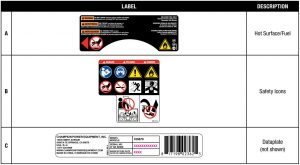
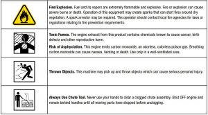
Safety LabelsThese labels warn you of potential hazards that can cause serious injury. Read them carefully.If a label comes off or becomes hard to read, contact Technical Support Team for possible replacement.
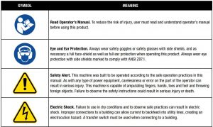
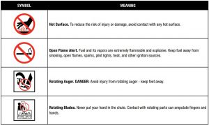
Safety SymbolsSome of the following symbols may be used on this product. Please study them and learn their meaning. Proper interpretation of these symbols will allow you to more safely operate the product.
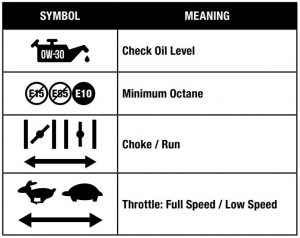
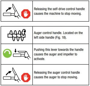
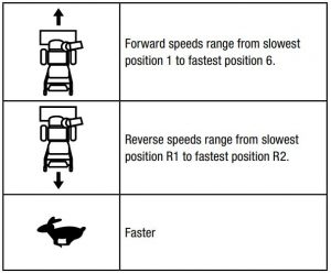
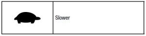
Operation SymbolsSome of the following symbols may be used on this product. Please study them and learn their meaning. Proper interpretation of these symbols will allow you to more safely operate the product.
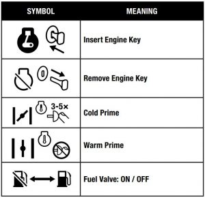
Quickstart Label SymbolsSome of the following symbols may be used on this product. Please study them and learn their meaning. Proper interpretation of these symbols will allow you to more safely operate the product.

Starting the Engine
- Turn fuel valve “ON” position.
- Move choke lever to “CHOKE” position.
- Move the throttle lever to “FULL” speed to start the engine.
- Make sure the engine safety key is inserted into the key hole.
- Priming the Engine5a. To start the COLD engine: Prime 3-5 times.5b. To start a WARM engine: DO NOT prime.
- Pull the recoil started to start the engine.
- Move the choke lever to “RUN” position.
Stopping the Engine
- Turn fuel valve “OFF” position.
- Remove the engine key.
CONTROLS AND FEATURES
Read this operator’s manual before operating your snowblower. Familiarize yourself with the location and function of the controls and features. Save this manual for future reference.
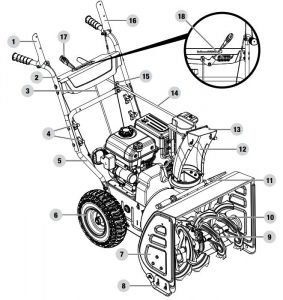
Snowblower
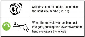
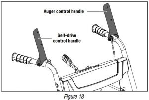
- Self-Drive Control Handle
- Upper Handles
- Speed Control Connecting Lever
- Handle Locking Knobs
- Lower Handle
- Wheels
- Auger Housing
- Adjustable Skid Shoes
- Auger
- Impeller
- Clean Out Tool
- Discharge Chute
- Discharge Deflector
- Discharge Chute Rotation Lever
- Discharge Chute Lever Guide
- Auger Control Handle
- Speed Adjusting Handle
- Shear Pin and Clip Storage
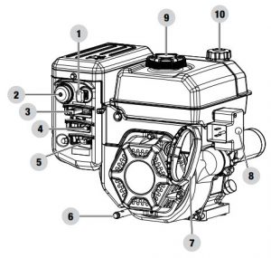
Engine
- Key (safety lock out)
- Primer Bulb
- Throttle Lever
- Choke Lever
- Fuel Valve (On/Off)
- Oil Drain Plug
- Recoil Starter Grip
- Electric Start Button
- Fuel Cap
- Oil Fill and Level Check Cap
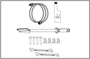
Parts IncludedAccessories
- 6 ft. (1.8 m) Electric Start Power Cord.. . . . . . . . . . . . . . . . . . . . . . . . . . . 1
- Engine Oil.. . . . . . . . . . . . . . . . . . . . . . . . . . . . . . . . . . . . . . 16.9 fl. oz. (500 ml)
- Chute Clearing Tool.. . . . . . . . . . . . . . . . . . . . . . . . . . . . . . . . . . . . . . . . . . . . . . . 1
- B Clip and Sheer Pins (spare parts).. . . . . . . . . . . . . . . . . . . . . . . . . . . . . . 4
Tools
- 10mm × 12mm Double Open End Wrench.. . . . . . . . . . . . . . . . . . . . . . . 2
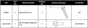
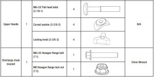
Assembly Parts
ASSEMBLY
Your snowblower requires some assembly. This unit ships from our factory with oil. It must be properly serviced with fuel and oil before operation.If you have any questions regarding the assembly of your snowblower, call our Technical Support Team at 1-877-338-0999. Please have your serial number and model number available.
Unpacking
- Set the shipping carton on a solid, flat surface.
- Remove everything from the carton except the snowblower base — including upper and lower handles, wheels, connecting levers, chute, hardware, etc. Make sure all the assembly parts are included before you start.
- Lift the top half of the box off and the base should be clear to start assembly.
- Cut down the bottom carton to allow a flat surface area to install the assembly parts without scratching parts or cutting tires. Alternatively, with team lift help, lift the base of the snowblower out of the carton and place it on a flattened carton to start assembly.
Lower Handle
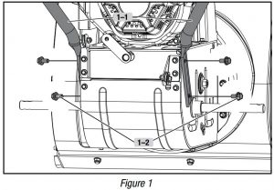
- Attach the lower handle (1-1) onto the unit body with bolts (1-2) (Fig. 1). Repeat on the other side.
Wheel
- Slide the left wheel (2-1) onto axle (2-2) as the arrow shows. Tread pattern should face forward. Place axle pin (2-3) into wheel. The axle has a center hole to attach the wheel to the axle (which connects to the drive train). Once inserted, fold ring around axle to hold in place (Fig. 2).
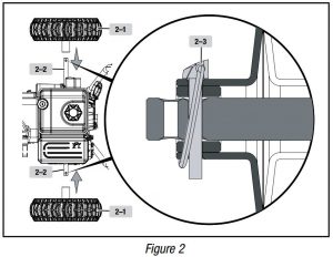
NOTICEOnly the left axle has two holes, and the axle pin can be removed and repositioned. If the wheel is slid further in on the axle with the pin inserted into the outside hole of the axle, the machine will move freely without the engine on. If the pin is inserted into the inside hole of the axle, the machine will only move when the drive control is engaged when the engine is on.
It is optional to slide one wheel past the pin hole in the axle and to place the locking pin into the axle outside the wheel without locking it into the drive axle. This creates a pivot wheel that allows the operator to more easily turn the snowblower during use by using the “free wheel” as a pivot point. Though this makes turning easier, it decreases drive wheel traction by 50%.
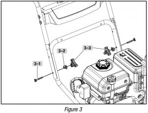
Upper Handle1. Connect the upper handle and lower handle with 2 bolts (3-1), 2 washers (3-2) and 2 locking knobs (3-3) only on the bottom – keep them loose so you can fold the handle down in the next step (Fig. 3).
Cables
- Cables are disconnected from each other and found on the base of the snowblower (near the auger housing) and on the upper handle.
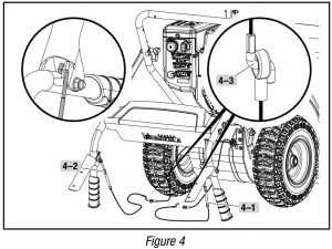
- Fold handle down backwards (it will require some force to fold backwards) and connect SELF-DRIVE CONTROL HANDLE CABLE (4-1) on the right, and AUGER CABLE (4-2) on the left. (Fig. 4).
- Insert wire clamps (4-3) together and pull to make sure they are connected. (Fig. 4).
NOTICEThe cables are preset by the factory. If you need to adjust see ADJUSTING SELF-DRIVE CONTROL HANDLE CABLES or ADJUSTING AUGER CONTROL CABLE for correct adjustments.
NOTICEIn the process of operation, if the auger or drive control handle is too loose, screw the bolt of part A to get a natural tension station for the wire.
Check the slack of the tension and adjust accordingly. You want to make sure that the tension on the lower side of the snowblower has 1⁄4-3⁄8 in. (6.4-9.5 mm) of movement. If the slack is greater than 5⁄8 in. (16 mm), please adjust. Proper tension is important because you will want your snowblower to move forward properly in heavy snowfalls.
Upper Handle
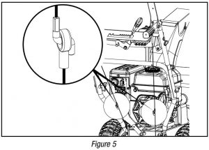
- Fold the upper handle up, making sure the cables pull tight (Fig 5).
NOTICE
Do not bend the SELF-DRIVE CONTROL HANDLE CABLE (4-1) and AUGER CABLE (4-2) bolts when folding upwards.
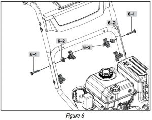
2. Connect the last 2 bolts (6-1), 2 washers (6-2) and 2 locking knobs (6-3) on the top (Fig. 6). Fully hand tighten all four locking knobs.
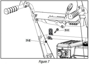
3. Discharge chute bracket should be placed forward as shown (for correct placement). Do not overtighten. Connect discharge chute guide to lower handle with 1 bolt (7-1), and 1 lock nut (7-2) (Fig. 7).
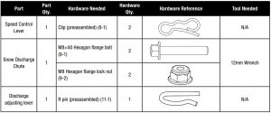
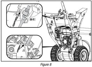
Speed Control Connecting Lever
- Connect the connecting lever and connecting base with cotter pin (8-1).
- Connect the connecting lever and speed adjusting handle with clip (Fig. 8).
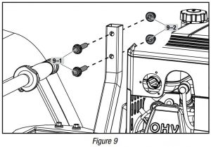
Snow Discharge Support
- Remove the bolts (9-1) and nuts (9-2) from the top of the discharge support (Fig. 9). Set aside for next step.
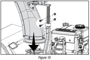
Snow Discharge Chute
- Put the snow discharge chute on the snow discharge support. Attach the snow discharge support using bolts (9-1) and nuts (9-2) removed in the prior step (Fig. 10). Fully hand tighten.
Discharge Chute Rotation Lever
- Remove the R-clip from the gear as applicable. Set aside for a later step. It may be preinstalled by the factory.
- Insert the lever through the discharge chute bracket on the lower handle, and then into the hole of the gear (Fig. 11A).
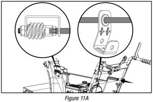
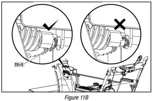
3. Align the lever and the gear, and then connect the R-clip (11-1). (Fig. 11B).4. Check the snow discharge chute by turning it fully in both directions. The discharge chute should rotate freely.
![]() WARNING
WARNING
Ensure the R pin is positioned as shown in Fig. 11B.
Add Engine Oil
![]() WARNING
WARNING
DO NOT attempt to crank or start the engine before it has been properly filled with the recommended type and amount of oil. Damage to the snowblower as a result of failing to follow these instructions will void your warranty.
NOTICEThe snowblower rotor has a sealed, pre-lubricated ball bearing that requires no additional lubrication for the life of the bearing.
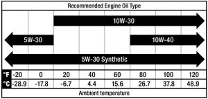
NOTICEThe recommended oil type for typical use is 0W-30 automotive oil.
If running snowblower in extreme temperatures, refer to the following chart for recommended engine oil type.
- Place the snowblower on a flat, level surface.
- Remove the oil cap/dipstick and wipe it clean (Fig. 12A).
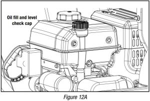
3. Insert the oil cap/dipstick into the oil filler neck but do not screw it in, then remove it to check the oil level (Fig. 12B).
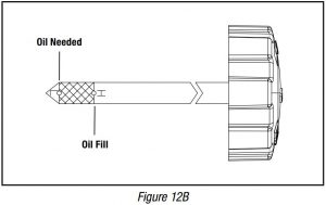
4. If the oil level is near or below the lower limit mark on the dipstick, remove the oil cap/dipstick, and fill with the recommended oil to the upper limit mark. Do not overfill (Fig. 12B).5. Reinstall the oil cap/dipstick.
NOTICEOnce oil has been added, a visual check should show oil about 1-2 threads from running out of the fill hole.When using the dipstick to check oil level, DO NOT screw in the dipstick while checking.
NOTICECheck oil level often during the initial 20 hour engine run period. Refer to the Maintenance section for recommended service intervals.
NOTICESynthetic oil may be used after the first oil change. Using synthetic oil does not decrease the recommended oil change interval. Full synthetic 5W-30 oil will aid in starting in cold ambient < 41º F (5º C) temperatures.
![]() CAUTIONThis engine is equipped with a low oil shut-off and will stop when the oil level in the crankcase falls below the threshold level.
CAUTIONThis engine is equipped with a low oil shut-off and will stop when the oil level in the crankcase falls below the threshold level.
Add FuelUse clean, fresh, regular unleaded gasoline with a minimum octane rating of 87 and an ethanol content of 10% or less by volume. ![]()
DO NOT mix oil with gasoline.
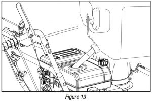
- Remove the fuel tank cap.
- Add fuel to the bottom of the fuel level limit in the neck of the fuel tank. Do not overfill. Wipe up spilled fuel before starting the snowblower. Fuel tank capacity: 0.7 gal. (2.6 L) (Fig. 13).
![]() CAUTIONUse unleaded gasoline with a minimum octane rating of 87 and an ethanol content of 10% or less by volume.
CAUTIONUse unleaded gasoline with a minimum octane rating of 87 and an ethanol content of 10% or less by volume.
- DO NOT light cigarettes or smoke when filling the tank.
- DO NOT mix oil and gasoline.DO NOT overfill the tank. Fill tank to approximately ¼ in. (6.4 mm) below the top of the tank to allow for gasoline expansion.
- DO NOT pump gasoline directly into the snowblower at the pump. Use an approved fuel container to transfer the gasoline to the snowblower.
- DO NOT fill tank indoors.
- DO NOT fill tank when the engine is running or hot.
![]() WARNINGPouring gasoline too fast through the fuel screen may result in gasoline splashing over the snowblower and operator while filling.
WARNINGPouring gasoline too fast through the fuel screen may result in gasoline splashing over the snowblower and operator while filling.
NOTICEThe snowblower engine works well with 10% or less ethanol blend gasoline. When using ethanol-gasoline blends there are some issues worth noting:
- Ethanol-gasoline blends can absorb more water than gasoline alone.
- These blends can eventually separate, leaving water or a watery goo in the tank, fuel valve and carburetor. The compromised gasoline can be drawn into the carburetor and cause damage to the engine and/or potential hazards.
- If a fuel stabilizer is used, confirm that it is formulated to work with ethanol-gasoline blends.
- Any damages or hazards caused by using improper gasoline, improperly stored gasoline, and/or improperly formulated stabilizers, are not covered by manufacturer’s warranty.
It is advisable to always shut off the gasoline supply and run the engine to starvation after each use. See Storage instructions for extended non-use.
OPERATION
![]() WARNINGNever use the snowblower without first reading and understanding the operating instructions, warnings and instruction labels located on the machine.
WARNINGNever use the snowblower without first reading and understanding the operating instructions, warnings and instruction labels located on the machine.
Before Operation
- Check the General Condition.
- Look around and underneath the engine for signs of oil or gasoline leaks.
- Remove any excessive dirt or debris, especially around the muffler and recoil starter.
- Look for signs of damage.
- Check that all shields and covers are in place, and all nuts, bolts, and screws are tightened.
Check the Engine
- There is no fuel or oil in the engine. Fill with fuel and add 0W-30 prior to first use.
- Check the fuel level (see Add Fuel under Assembly section).
- Check the oil level (see Add Engine Oil under Assembly section).
![]() WARNINGAlways check the engine oil level before operation. Using the snowblower without oil can seriously damage the engine and void your warranty. The machine must stand on level ground when checking.
WARNINGAlways check the engine oil level before operation. Using the snowblower without oil can seriously damage the engine and void your warranty. The machine must stand on level ground when checking.
Engine key and throttle lever plastic piece need to be attached before first use. These parts may be attached to the recoil starter grip. Please remove the key and throttle lever from the recoil starter grip and attach/install properly.
![]() WARNINGAlways wear eye protection with side shields marked to comply with ANSI Z87.1. Failure to do so could result in objects being thrown into your eyes and other possible serious injuries.
WARNINGAlways wear eye protection with side shields marked to comply with ANSI Z87.1. Failure to do so could result in objects being thrown into your eyes and other possible serious injuries.
![]() Starting the Engine
Starting the Engine
- Make sure the engine key (safety lock out) is inserted into the key hole.
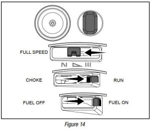
- To start a warm engine: (Fig. 14).2a. Move the fuel valve lever to the ON position.2b. Move the choke lever to the RUN position.2c. Move the throttle lever to full speed.2d. Do not prime.
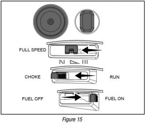
3. To start a cold engine: (Fig. 15).
3a. Move the fuel valve lever to the ON position.3b. Move the choke lever to the CHOKE position.3c. Move the throttle lever to full speed.3d. Prime 3-5 times.
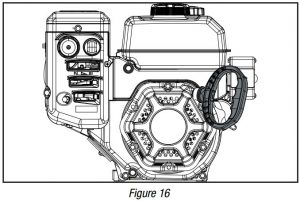
4. Stand back and to the right of the unit, pull the starter grip lightly until you feel resistance then pull briskly. Return the starter grip gently (Fig. 16).
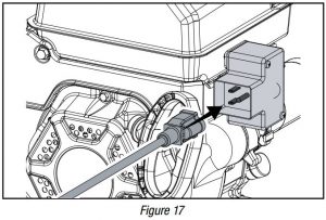
5. Alternatively. for electric start, plug in the supplied electrical cord into the starter. Press the electric start button and make sure that the mains supply voltage is 120 V~ 60 Hz (Fig. 17).
6. To start a cold engine: When the engine starts, move the choke to RUN position.
Stopping the EngineTo stop the engine in an emergency situation or during normal operation, simply remove the engine key.
Operation at High AltitudeThe density of air at high altitudes is lower than at sea level. Engine power is reduced as the air mass and air-fuel ratio decrease. Engine power and snowblower output will be reduced approximately 3½% for every 1000 ft. of elevation above sea level. At high altitudes increased exhaust emissions can also result due to the increased enrichment of the air fuel ratio. Other high altitude issues can include hard starting, increased fuel consumption and spark plug fouling.
To alleviate high altitude issues other than the natural power loss, CPE can provide a high altitude carburetor main jet. The alternative main jet and installation instructions can be obtained by contacting our Technical Support Team. Installation instructions are also available in the Technical Bulletin area of the CPE website.
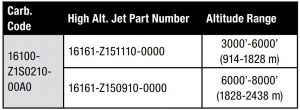
The part number and recommended altitude range for the application of the high altitude carburetor main jet is listed in the following table.
In order to select the correct high altitude main jet it is necessary to identify the carburetor model. For this purpose, a code is stamped on the side of the carburetor. Select the correct high altitude jet part number corresponding to the carburetor code found on your particular carburetor.
![]() WARNINGOperation using the alternative main jet at elevations lower than the recommended minimum altitude can damage the engine. For operation at lower elevations, the originally supplied standard main jet must be used. Operating the engine with the wrong engine configuration at a given altitude may increase its emissions and decrease fuel efficiency and performance.
WARNINGOperation using the alternative main jet at elevations lower than the recommended minimum altitude can damage the engine. For operation at lower elevations, the originally supplied standard main jet must be used. Operating the engine with the wrong engine configuration at a given altitude may increase its emissions and decrease fuel efficiency and performance.
Control Levers
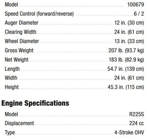
Drive SystemYour snowblower has 6 forward speeds and 2 reverse to regulate forward and backward motion (Fig. 19).
Adjusting the self-propelled drive system:
- Release the self-drive control handle to bring the snowblower to a stop.
- Move the speed-control lever to the gear (either forward or reverse) that you require (Fig. 19).
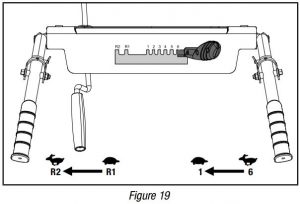
3. Press the self-drive control handle to engage the drive system.
![]() WARNINGWatch out for rotating auger. Keep hands, feet, hair and loose clothing away from any moving parts on the machine.
WARNINGWatch out for rotating auger. Keep hands, feet, hair and loose clothing away from any moving parts on the machine.
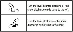
Adjusting the Snow Discharge Direction and HeightChange discharge direction:
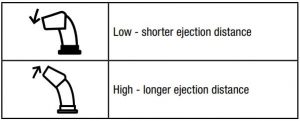
Change discharge height:
- Loosen the locking knob to adjust the snow discharge deflector to a suitable height (Fig. 20).
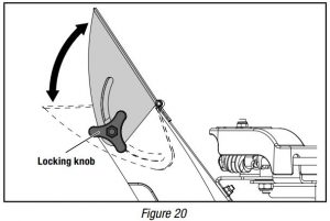
2. Adjust the snow discharge deflector from 0 – 60°.3. Tighten the locking knob.
![]() WARNINGIf snow clogs the discharge chute do not try to remove it before:
WARNINGIf snow clogs the discharge chute do not try to remove it before:
- Releasing the auger control handle.
- Stopping the engine.
- Disconnecting the cable from the spark plug.
Do not put your hand inside the chute or auger. Use the chute clearing tool included with your snowblower.
Adjusting the Snow ShoesSet the height of the auger housing above the ground using the shoes.Adjust the shoes to suit the ground conditions:
- On flat ground, e.g. asphalt, the shoes should be adjusted to about 1⁄5 in. (5 mm) (the distance from the auger to the ground) (Fig. 19).
- On uneven ground, e.g. gravel paths, the shoes should be adjusted to about 11⁄5 in. (30 mm) (the distance from the auger to the ground) (Fig. 21).
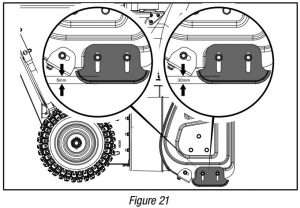
To adjust the shoes
- Loosen the nuts.
- Move the shoes upward or downward to adjust height.
- Tighten the nuts.
![]() WARNINGAlways adjust the shoes so that gravel and stones are not fed into the snowblower. There is a risk for personal injury if these are thrown out at high speed.Ensure the shoes are adjusted the same on both sides.
WARNINGAlways adjust the shoes so that gravel and stones are not fed into the snowblower. There is a risk for personal injury if these are thrown out at high speed.Ensure the shoes are adjusted the same on both sides.
![]() WARNINGDo not at any time make any adjustment to machine without first stopping the engine and disconnecting the spark plug wire.
WARNINGDo not at any time make any adjustment to machine without first stopping the engine and disconnecting the spark plug wire.
![]() WARNINGBefore changing height, stop engine and disconnect spark plug cable.
WARNINGBefore changing height, stop engine and disconnect spark plug cable.
After Use
- Check for loose or damaged parts. If required, change damaged parts.
- Tighten loose screws and nuts.
- Brush all the snow from the machine.
- Move all the controls backwards and forwards a few times.
- Disconnect the spark plug wire from the spark plug.
MAINTENANCE
![]() WARNINGAlways disconnect the spark plug wire during times of inactivity, cleaning and maintenance. This will prevent any accidental start up that may cause damage or injury.
WARNINGAlways disconnect the spark plug wire during times of inactivity, cleaning and maintenance. This will prevent any accidental start up that may cause damage or injury.
![]() WARNINGNever operate a damaged or defective snowblower
WARNINGNever operate a damaged or defective snowblower
![]() WARNINGImproper maintenance will void your warranty.
WARNINGImproper maintenance will void your warranty.
NOTICEFor Emission control devices and systems, read and understand your responsibilities for service as stated in the Emission Control Warranty Statement of this manual.
Engine Maintenance
Safety PrecautionsMake sure the engine is off before you begin any maintenance or repair. This will eliminate several potential hazards:
- Carbon monoxide poisoning from engine exhaust — never run the machine indoors. The exhaust fumes contain carbon monoxide, a very toxic gas.
- Burns from hot parts — let the engine cool for 30 minutes before touching hot parts.
- Injury from moving parts — read the instructions before you begin, and make sure you have the tools and skills required.
To reduce the possibility of fire or explosion, be careful when working around gasoline. Use only a nonflammable solvent, not gasoline, to clean parts. Keep cigarettes, sparks and flames away from all fuel-related parts.
![]() WARNINGDo not cover the machine while the engine and muffler are still hot.
WARNINGDo not cover the machine while the engine and muffler are still hot.
Regular Service PeriodsPerform at every indicated month or operating hour interval, whichever comes first.
EACH USE
- Check oil level
EVERY MONTH OR 20 HOURS
- Change oil
EVERY 6 MONTHS OR 100 HOURS
- Change oil
- Check/clean spark plug
- Clean spark arrester
EVERY YEAR OR 150 HOURS
- Replace spark plug
- Check/adjust idle speed*
- Check/adjust valve clearance*
- Clean fuel tank and strainer*
EVERY 2 YEARS (REPLACE IF NECESSARY)
- Check fuel line
* These items should be serviced by your servicing dealer unless you have the proper tools and are mechanically proficient. Refer to manual for service procedures.
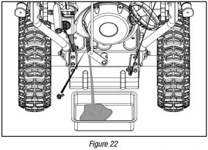
Oil ChangeDrain the engine oil when the engine is warm. Warm oil drains quickly and completely.
- Turn the fuel valve lever to the OFF position to reduce the possibility of fuel spillage.
- Place a suitable container below the snowblower to catch the used oil.
- Remove the drain bolt and drain the oil into the container by slightly tipping the engine toward the oil cap/dipstick (Fig. 22).
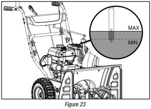
4. With the engine in a level position, fill to the upper limit mark on the dipstick with the recommended oil (0W-30) (Fig. 23).
5. Reinstall the oil cap/dipstick securely. Capacity of engine oil: 16.9 fl. oz. (0.5 L).
![]() WARNING
WARNING
- Running the engine with a low oil level can cause engine damage.
- With engine off but still warm, disconnect the spark plug wire and keep it away from the spark plug.
![]() WARNINGUsed oil is a hazardous waste product and must be disposed of properly. Do not discard with household waste. Check with your local regulations, service center, or dealer for safe disposal/recycling facilities.
WARNINGUsed oil is a hazardous waste product and must be disposed of properly. Do not discard with household waste. Check with your local regulations, service center, or dealer for safe disposal/recycling facilities.
Cleaning and Adjusting the Spark Plug(s)
- Remove the spark plug cable from the spark plug.
- Use a spark plug socket (not included) to remove the plug.
- Inspect the electrode on the plug. It must be clean and not worn to produce the spark required for ignition.
- Make certain the spark plug gap is 0.7 – 0.8 mm (0.028 – 0.031 in.).

5. Refer to the spark plug section on the Specifications page when replacing the plug.6. Carefully thread the plug into the engine. 7. Use a spark plug socket (not included) to firmly install the plug.8. Attach the spark plug wire to the plug.
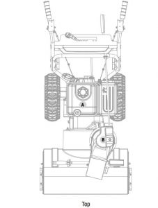
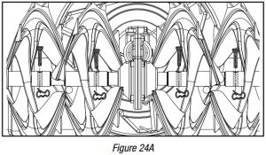
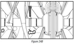
Replacing Shear PinsThe auger housing is shown as Fig. 24A. The augers are secured to the auger drive with shear pins (A) and clips (B) (Fig. 24B). If the auger should strike a foreign object or ice jam, the snowblower is designed so that the lock pins may shear.
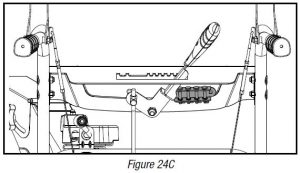
If the augers will not turn, check to see if the lock pins have sheared (Fig. 24B). Replacement shear pin(s) and clip(s) are found on the back of the control panel (Fig. 24C).
![]() WARNINGNo service must be carried out before:
WARNINGNo service must be carried out before:
- The engine has stopped.
- The spark plug cable has been disconnected from the spark plug.
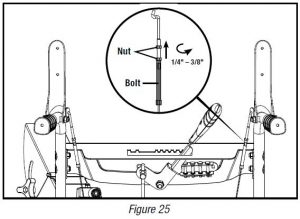
Adjusting Self-Drive Control Handle CableCheck the slack of the tension and adjust accordingly. Make sure that the tension on the self-drive cable is adjusted so it has between 1⁄4-3⁄8 in. (6.4-9.5 mm) of movement. This movement can be acquired by measuring the distance the engagement paddle moves from its starting position and the point it becomes taut and starts to move the transmission adjustment lever. If the slack is greater than 5⁄8 in. (16 mm), please adjust. Proper tension is important because you will want your snowblower to move forward properly in heavy snowfalls.
While operating the snowblower, if the self-drive control lever is too loose, tighten the nut counter-clockwise while at the same time rotating the bolt upward to reach the position of the nut (Fig. 25).
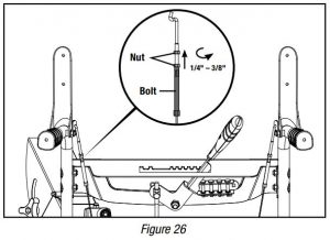
Adjusting Auger Control CableCheck the slack of the tension and adjust accordingly. Make sure that the tension on the auger control cable is adjusted so it has between 1⁄4-3⁄8 in. (6.4-9.5 mm) of movement. This movement can be acquired by measuring the distance the engagement paddle moves from its starting position and the point it becomes taut and starts to engage the auger. If the slack is greater than 5⁄8 in. (16 mm), please adjust. Proper tension is important because you will want your snowblower to maximize belt life in heavy snowfalls.
While operating the snowblower, if the auger control lever is too loose, tighten the nut counter-clockwise while at the same time rotating the bolt upward to reach the position of the nut (Fig. 26).
Replace Auger Drive Belt Without SplittingThe Snowblower Body (Option 1)
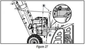
- Remove the plastic belt cover (A) on the front of the engine by removing two M6 × 16 bolts (B) (Fig. 27).
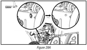
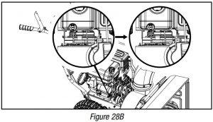
2. Remove clip and washer (Fig. 28A), pull support rod ½ way out from other side of snowblower (Fig. 28B).
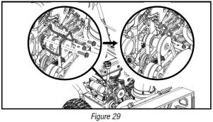
3. Remove the 2 bolts (20 mm/30 mm) holding the belt guard (Fig. 29). Note the spring is loose at this point.
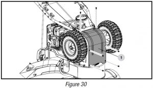
4. Carefully pivot the snowblower up and forward so that it rests on the auger housing. Place a piece of cardboard or moving blanket on the ground before tipping forward. Make sure all fluids are removed and spark plug is disconnected.5. Remove the base frame cover (1) from the underside of the snowblower by removing the six M6 × 16 screws which secure it (Fig 30).
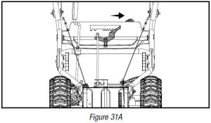
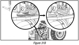
6. Slide the speed adjusting handle to the right (Fig. 31A) and remove the loose belt by cutting it or any remaining belt pieces if the belt has already broken (Fig. 31B). If cutting the belt be careful of the tensioning pulley and arm as they are spring loaded and could cause injury when the belt is cut.
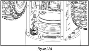
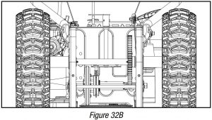
7. Slip the new auger drive belt into the compartment from the bottom of the snowblower placing it around the bottom of the auger drive pulley and slipping it around the front pulley on the engine. Ensure the belt is positioned between the bottom belt guard and the bottom of the auger drive pulley. You may need to remove the bolt holding the lower belt guard in place to properly seat the belt into the pulley. Replace the belt guard and bolt after installing the belt into the pulley (Fig. 32A/B).
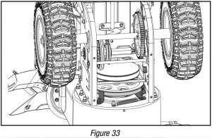
8. Ensure belt is seated below the belt guide on the idler pulley pivot arm (Fig. 33).
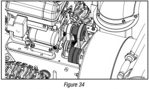
9. With the belt properly placed on both the front pulley and the auger drive pulley, pull the auger idler pulley back away from the belt and slip the belt inside the pulley. You can pull the recoil to rotate the pulley to help get it seated (Fig. 34).
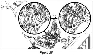
10. Place the belt guard back into place and install the (20 mm/30 mm) bolts that were removed earlier. Once reinstalled, make sure there is equal distance on both sides between the pulley and the guard (Fig. 35).
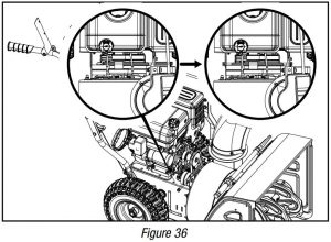
11. Reassemble the support rod by pushing back into place and ensure that it is properly engaged into the friction disc assembly and replace the washer and clip (Fig. 36).
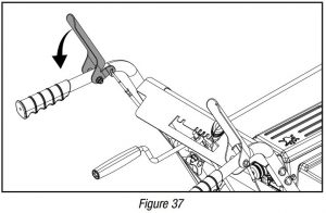
12. Pull the auger control handle to ensure the idler pulley is properly engaging the belt (Fig. 37). Under the belt cover area, make sure the distance on both sides between the guide and pulley is the same.
13. Reinstall the base frame cover.14. Install the plastic belt cover using two M6 × 16 bolts set aside from an earlier step. Torque until snug. Do not overtighten or you risk damaging the plastic belt cover.15. Perform a drive test to confirm everything is in working order.
Replace Auger Drive Belt – Splitting The Snowblower Body (Option 2)
Tools required:
- Size 10 wrench (included).
- Size 12 wrench (included).
- Size 13 wrench (not included).
To remove and replace your snowblower’s drive belt, proceed as follows:
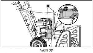
- Remove the plastic belt cover (A) on the front of the engine byremoving two M6 × 16 bolts (B) (Fig. 38).
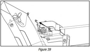
2. Pull out the R pin (Fig. 39).
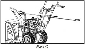
3. Remove the lever from the discharge chute bracket (Fig. 40).
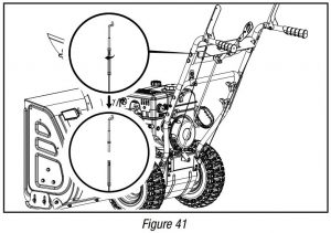
4. Unscrew the bolt of auger control wire (Fig. 41).
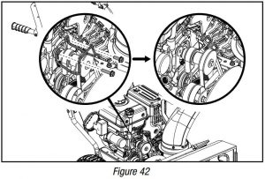
5. Remove the 2 bolts (20 mm/30 mm) holding the belt guard (Fig. 42). Note the spring is loose at this point.
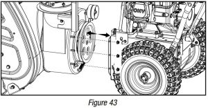
6. Unscrew six M8 nuts to separate the auger housing from the base (Fig. 43).
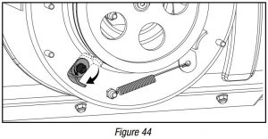
7. Unscrew the bolt on the belt guard (Fig. 44).
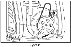
8. Split the drive belt off the pulley. Remove and replace the belt in reverse order ensuring that the new belt is below the spring loaded idler pulley (Fig. 45).
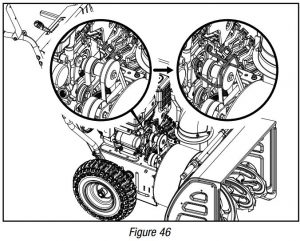
9. Place the belt guard back into place and install the bolts (20 mm/30 mm) that were removed earlier. Once reinstalled, make sure there is equal distance on both sides between the pulley and the guard (Fig. 46).
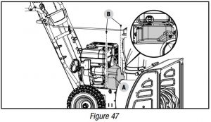
10. Install the plastic belt cover (A) using two M6 × 16 bolts (B) set aside from an earlier step. Torque until snug. Do not overtighten or you risk damaging the plastic belt cover (Fig. 47).
11. Perform a drive test to confirm everything is in working order.
Repair or Replace Friction DiskNOTICEIf the snowblower fails to drive with the drive control engaged, and after performing the drive control cable adjustment fails to correct the problem, the friction disc may need to be replaced.
NOTICETo prevent spillage, remove all fuel from tank by running the engine until it stops. Do not attempt to pour out fuel from the engine. Disconnect the spark plug before performing any service.
Tools required:
- Size 10 wrench (included).
- Size 17 wrench (not included).
To remove and replace your snowblower’s friction disc, proceed as follows:
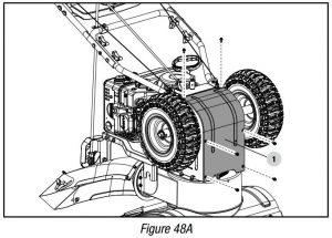
- Carefully pivot the snowblower up and forward so that it rests on the auger housing. Place a piece of cardboard or moving blanket on the ground before tipping forward. Make sure all fluids are removed and spark plug is disconnected.
- Remove the base frame cover (1) from the underside of the snowblower by removing the six M6 × 16 screws which secure it (Fig. 48A).
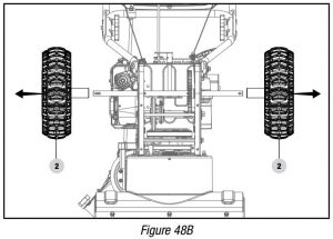
3. Remove the right wheel (2) by removing the axle pin on it (Fig. 48B).
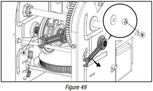
4. Carefully remove the M10 hex nut (3) which secures the hex shaft (4) to the snowblower frame and lightly tap the shaft’s end to dislodge the ball bearing from the right side of the frame (Fig. 49).
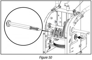
5. Carefully position the hex shaft downward and to the left before carefully sliding the friction disc assembly (5) off the shaft (Fig. 50).
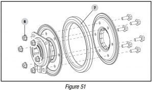
6. Unscrew the six M6 × 16 bolts (6) of the friction disc assembly to discard the worn friction wheel rubber ring (7) and replace with a new one (Fig. 51).
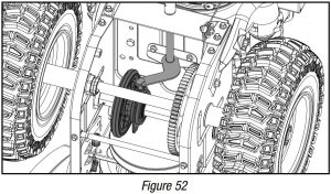
7. Follow the previous steps in reverse order to reassemble the parts (Fig. 52).
8. Perform a drive test to confirm everything is in working order.
LubricationLubricate the linkage every 10 hours of use and before long-term storage. Use 0W-30 oil.
No parts inside the gearbox are to be lubricated. All bearings and bushings are permanently lubricated and require no maintenance. Lubricating these parts will only result in the grease getting on to the friction wheel and disc drive plate, which could damage the rubber clad friction wheel.
STORAGE
Never store the machine with gasoline in the fuel tank in a confined area with bad ventilation. Gasoline fumes could reach open flames, sparks and cigarettes etc.
To avoid the engine freezing and problems starting the engine, leave the engine running outdoors for 5-10 minutes after your work has been completed, then shut the engine off. This will ensure all moisture will disappear that would otherwise cause starting problems. After engine shut down, allow the engine to cool before storing in any enclosure.
If the machine is to be stored for a longer period than 30 days, the following procedures are recommended.
- Start the engine and let it run until it stops due to lack of fuel.
- Change the engine oil if it has not been done for 3 months.
- Remove the spark plug and add about 1oz.(30ml) of engine oil in the spark plug hole. Pull recoil handle manually and crank the engine a couple of times to disperse the oil within the cylinder. Replace spark plug.
- Clean the whole machine thoroughly.
- Lubricate all the parts as shown in LUBRICATION section above.
- Inspect the machine for damage, and repair if necessary.
- Touch up any paint damage.
- Apply rust protection to the metal surfaces.
- Store the machine indoors when possible.
TransportingIf the engine has been running, allow it to cool for at least 15 minutes before loading the machine on the transport vehicle. A hot engine and exhaust system can burn you and can ignite some materials.Move the fuel valve lever to the OFF position and keep the engine level when transporting to reduce the possibility of fuel leakage.
SPECIFICATIONS
Snowblower Specifications
NOTICEA technical bulletin regarding valve adjustment procedures is available at www.championpowerequipment.com.
Oil SpecificationsDO NOT OVERFILL.Type.. . . . . . . . . . . . . . . . . . . . . . . . . . . . . . . . . . . . . . . . . . . . . . . . . . . . . . . . . . 0W-30Capacity.. . . . . . . . . . . . . . . . . . . . . . . . . . . . . . . . . . . . . . . 16.9 fl. oz. (500 ml)
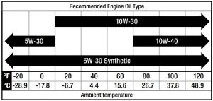
NOTICETemperature will affect engine oil and engine performance. Change the type of engine oil used based on temperature shown in the “Recommended Engine Oil Type” table.
Fuel SpecificationsUse regular unleaded gasoline with a minimum octane rating of 87 and an ethanol content of less than 10% by volume. DO NOT USE E15 or E85. DO NOT OVERFILL.
Gasoline Capacity.. . . . . . . . . . . . . . . . . . . . . . . . . . . . . . . . . . . 0.7 gal. (2.6 L)
TROUBLESHOOTING
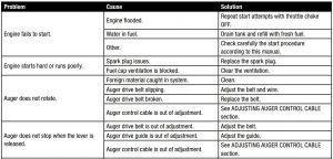
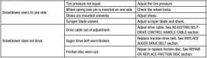
For further technical support:
Technical Support TeamMon-Fri 8:30 AM-5:00 PM (PST/PDT)Toll Free 1-877-338-0999
WARRANTY*
CHAMPION POWER EQUIPMENT2 YEAR LIMITED WARRANTY
Warranty QualificationsTo register your product for warranty and FREE lifetime call center technical support please visit: https://www.championpowerequipment.com/registerTo complete registration you will need to include a copy of the purchase receipt as proof of original purchase. Proof of purchase is required for warranty service. Please register within ten (10) days from date of purchase.
Repair/Replacement WarrantyCPE warrants to the original purchaser that the mechanical and electrical components will be free of defects in material and workmanship for a period of two years (parts and labor) from the original date of purchase and 90 days (parts and labor) for commercial and industrial use. Transportation charges on product submitted for repair or replacement under this warranty are the sole responsibility of the purchaser. This warranty only applies to the original purchaser and is not transferable.
Do Not Return The Unit To The Place Of PurchaseContact CPE’s Technical Service and CPE will troubleshoot any issue via phone or e-mail. If the problem is not corrected by this method, CPE will, at its option, authorize evaluation, repair or replacement of the defective part or component at a CPE Service Center. CPE will provide you with a case number for warranty service. Please keep it for future reference. Repairs or replacements without prior authorization, or at an unauthorized repair facility, will not be covered by this warranty.
Warranty ExclusionsThis warranty does not cover the following repairs and equipment:
Normal WearProducts with mechanical and electrical components need periodic parts and service to perform well. This warranty does not cover repair when normal use has exhausted the life of a part or the equipment as a whole.
Installation, Use and MaintenanceThis warranty will not apply to parts and/or labor if the product is deemed to have been misused, neglected, involved in an accident, abused, loaded beyond the product’s limits, modified, installed improperly or connected incorrectly to any electrical component. Normal maintenance is not covered by this warranty and is not required to be performed at a facility or by a person authorized by CPE.
Other ExclusionsThis warranty excludes:
- Cosmetic defects such as paint, decals, etc.
- Wear items such as belts, cables, shear pins, etc.
- Failures due to acts of God and other force majeure events beyond the manufacturer’s control.
- Problems caused by parts that are not original Champion Power Equipment parts.
Limits of Implied Warranty and Consequential Damage
Champion Power Equipment disclaims any obligation to cover any loss of time, use of this product, freight, or any incidental or consequential claim by anyone from using this product.
THIS WARRANTY AND THE ATTACHED U.S. EPA and/or CARB EMISSION CONTROL SYSTEM WARRANTIES (WHEN APPLICABLE) ARE IN LIEU OF ALL OTHER WARRANTIES, EXPRESS OR IMPLIED, INCLUDING WARRANTIES OF MERCHANTABILITY OR FITNESS FOR A PARTICULAR PURPOSE.
A unit provided as an exchange will be subject to the warranty of the original unit. The length of the warranty governing the exchanged unit will remain calculated by reference to the purchase date of the original unit.
This warranty gives you certain legal rights which may change from state to state or province to province. Your state or province may also have other rights you may be entitled to that are not listed within this warranty.
Contact InformationAddressChampion Power Equipment, Inc.12039 Smith Ave.Santa Fe Springs, CA 90670 USAwww.championpowerequipment.com
Customer ServiceToll Free: 1-877-338-0999Fax no.: 1-562-236-9429
Technical ServiceToll Free: 1-877-338-0999EMERGENCY 24 HOUR SUPPORT: 1-562-204-1188
CHAMPION POWER EQUIPMENT, INC. (CPE),THE UNITED STATES ENVIRONMENTAL PROTECTION AGENCY (U.S. EPA) AND THE CALIFORNIA AIR RESOURCES BOARD (CARB) EMISSION CONTROL SYSTEM WARRANTY
Your Champion Power Equipment (CPE) engine complies with both the U.S. EPA and state of California Air Resources Board (CARB) emissions regulations.
YOUR WARRANTY RIGHTS AND OBLIGATIONS:The US EPA, California Air Resources Board, and CPE are pleased to explain the Federal and California Emission Control Systems warranty on your 2020 small off-road engine (SORE) and equipment. In the United States and California, new small off-road engines (SORE) and new equipment that use small off-road engines (SORE) must be designed, built and equipped to meet the State’s stringent anti-smog standards.
CPE must warrant the emission control system on your small off-road engine (SORE) and equipment for the period of time listed below, provided there has been no abuse, neglect or improper maintenance of your small off-road engine (SORE) and equipment leading to the failure of the emission control system.
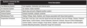
Your emission control system may include parts such as the carburetor, fuel-injection system, the ignition system, catalytic converter, fuel tanks, fuel lines (for liquid fuel and fuel vapors), fuel caps, valves, canisters, filters, clamps, connectors, and other associated components. Also included may be hoses, belts, and other emission related assemblies. Where a warrantable condition exits, CPE will repair your small off-road engine (SORE) and equipment at no cost to you including diagnosis, parts and labor.
MANUFACTURER’S WARRANTY COVERAGE:This Emissions Control System is warranted for two years. If any emissions-related part on your small off-road engine (SORE) and equipment is defective, the part will be repaired or replaced by CPE.
OWNER WARRANTY RESPONSIBILITIES:As the small off-road engine (SORE) and equipment owner, you are responsible for the performance of the required maintenance listed in your Owner’s Manual. CPE recommends that you retain all your receipts covering maintenance on your small off-road engine (SORE) and equipment, but CPE cannot deny warranty coverage solely for the lack of receipts or for your failure to ensure the performance of all scheduled maintenance.
As the small off-road engine (SORE) and equipment owner, you should be aware that CPE may deny you warranty coverage if your small off-road engine (SORE) and equipment or a part has failed due to abuse, neglect, improper maintenance or unapproved modifications.
You are responsible for presenting your small off-road engine (SORE) and equipment to an Authorized CPE service outlet or alternate service outlet as described in (3)(f.) below, CPE dealer or CPE, Santa Fe Springs, Ca. as soon as a problem exists. The warranty repairs shall be completed in a reasonable amount of time, not to exceed 30 days.
If you have any questions regarding your warranty coverage, you should contact:
Champion Power Equipment, Inc.Customer Service12039 Smith Ave.Santa Fe Springs, CA 906701-877-338-0999
EMISSION CONTROL SYSTEM WARRANTY
The following are specific provisions relative to your Emission Control System (ECS) Warranty Coverage.
- APPLICABILITY: This warranty shall apply to 1995 and later model year California small off-road engines (SORE) (for other states, 1997 and later model year engines). The ECS Warranty Period shall begin on the date the new engine or equipment is delivered to itsoriginal, end-use purchaser, and shall continue for 24 consecutive months thereafter.
- GENERAL EMISSIONS WARRANTY COVERAGECPE warrants to the original, end-use purchaser of the new engine or equipment and to each subsequent purchaser that each of its small off-road engines (SORE) is:2a. Designed, built and equipped so as to conform to U.S. EPA emissions standards for spark- ignited engines at or below 19 kilowatts and all applicable regulations adopted by the California Air Resources Board; and2b. Free from defects in materials and workmanship that cause the failure of a warranted part to be identical in all material respects to the part as described in the engine manufacturer’s application for certification for a period of two years.
- THE WARRANTY ON EMISSION-RELATED PARTS WILL BE INTERPRETED AS FOLLOWS:
- 3a. Any warranted part that is not scheduled for replacement as required maintenance in the Owner’s Manual shall be warranted for the ECS Warranty Period. If any such part fails during the ECS Warranty Period, it shall be repaired or replaced by CPE according to Subsection “d” below. Any such part repaired or replaced under the ECS Warranty shall be warranted for a time not less than the remainder of the ECS Warranty Period.
- 3b. Any warranted, emissions-related part which is scheduled only for regular inspection as specified in the Owner’s Manual shall be warranted for the ECS Warranty Period. A statement in such written instructions to the effect of “repair or replace as necessary” shall advise owners of the warranty coverage for emission related parts. Replacement within the warranty period is covered by the warranty and shall not reduce the ECS Warranty Period. Any such part repaired or replaced under the ECS Warranty shall be warranted for a time not less than the remainder of the ECS Warranty Period.
- 3c. Any warranted, emissions-related part which is scheduled for replacement as required maintenance in the Owner’s Manual shall be warranted for the period of time prior to the first scheduled replacement point for that part. If the part fails prior to the first scheduled replacement, the part shall be repaired or replaced by CPE according to Subsection “d” below. Any such emissionsrelated part repaired or replaced under the ECS Warranty, shall be warranted for a time not less than the remainder of the ECS Warranty Period prior to the first scheduled replacement point for such emissions-related part.
- 3d. Repair or replacement of any warranted, emissions-related part under this ECS Warranty shall be performed at no charge to the owner at a CPE Authorized Service Outlet.
- 3e. The owner shall not be charged for diagnostic labor which leads to the determination that a part covered by the ECS Warranty is in fact defective, provided that such diagnostic work is performed at a CPE Authorized Service Outlet.
- 3f. CPE shall pay for covered emissions warranty repairs at non-authorized service outlets under the following circumstances:i. The service is required in a population center with a population over 100,000 according to U.S. Census 2000 without a CPE Authorized Service Outlet ANDii. The service is required more than 100 miles from a CPE Authorized Service Outlet. The 100 mile limitation does not apply in the following states: Alaska, Arizona, Colorado, Hawaii, Idaho, Montana, Nebraska, Nevada, New Mexico, Oregon, Texas, Utah and Wyoming.
- 3g. CPE shall be liable for damages to other original engine components or approved modifications proximately caused by a failure under warranty of an emission-related part covered by the ECS Warranty.
- 3h. Throughout the ECS Warranty Period, CPE must maintain a supply of warranted emission-related parts sufficient to meet the expected demand for such emission-related parts and must obtain additional parts if that supply is exhausted.
- 3i. Any CPE Authorized and approved emission-related replacement part that do not increase the exhaust or evaporative emissions of the engine or emissions control system may be used in the performance of any ECS Warranty maintenance or repair and will be provided without charge to the owner. Such use shall not reduce CPE’s warranty obligation.
- 3j. Unapproved add-on or modified parts may not be used to modify or repair a CPE engine. Such use voids this ECS Warranty and shall be sufficient grounds for disallowing an ECS Warranty claim. CPE shall not be liable hereunder for failures of any warranted parts of a CPE engine caused by the use of such an unapproved add-on or modified part.
EMISSION-RELATED PARTS INCLUDE THE FOLLOWING: (using those portions of the list applicable to the engine)
TO OBTAIN WARRANTY SERVICE:You must take your CPE engine or the product on which it is installed, along with your warranty registration card or other proof of original purchase date, at your expense, to any Champion Power Equipment dealer who is authorized by Champion Power Equipment, Inc. to sell and service that CPE product during his normal business hours. Alternate service locations defined in Section (3)(f.) above must be approved by CPE prior to service. Claims for repair or adjustment found to be caused solely by defects in material or workmanship will not be denied because the engine was not properly maintained and used.
If you have any questions regarding your warranty rights and responsibilities, or to obtain warranty service, please write or call Customer Service at Champion Power Equipment, Inc.
Champion Power Equipment, Inc.12039 Smith Ave.Santa Fe Springs, CA 906701-877-338-0999Attn.: Customer Service
Champion 24 In. 2-Stage Snowblower User Manual – 100679 – Champion 24 In. 2-Stage Snowblower User Manual – 100679 –
Questions about your Manual? Post in the comments!
[xyz-ips snippet=”download-snippet”]