![]() Champion Power Equipment, Inc., Santa Fe Springs, CA the USAMODEl #100485
Champion Power Equipment, Inc., Santa Fe Springs, CA the USAMODEl #100485
PARTS INFORMATION9200W ELECTRONIC FUEL INJECTION GENERATORSERIAL NUMBER RANGE: ALL
 To order replacement parts please visit: shop.championpowerequipment.com or call 1-877-338-0999.
GENERATOR PARTS DIAGRAM
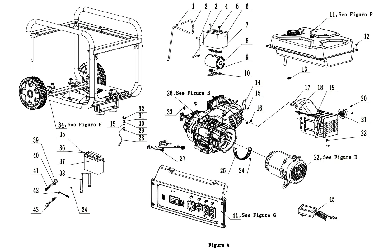
GENERATOR PARTS lIST
| # | Part Number | Description | Qty. |
| 1 | 2/6/1906 | Clamp 07 x 01 | 2 |
| 2 | 152.070014.05 | Tube, Fuel Tank Vent | 1 |
| 3 | 152.070013.03 | Tube, Carbon Canister Vent, 135 mm | 1 |
| 4 | 2/6/1904 | Clamp, 08 x 01 | 1 |
| 5 | 1.5789.0608.1 | Flange Bolt M6 x 8, Black | 2 |
| 6 | 152.070018.03 | Board, Heat Insulation | 1 |
| 7 | 152.070702.06 | Bracket, Carbon Canister Top | 1 |
| 8 | 152.070700.02 | Carbon Canister, 650 cc | 1 |
| 9 | 1.16674.0812 | Flange Bolt M8 x 12 | 2 |
| 10 | 152.070702.05 | Bracket, Carbon Canister Bottom | 1 |
| 11 | 152.070000.49.48 | Fuel Tank, 29L, Yellow, See Figure E | 1 |
| 12 | 2.08.143.1 | Flange Bolt/Washer Assembly M6 x 20, Black | 4 |
| 13 | 2/6/1929 | Clip 015 | 1 |
| 14 | 45.090006.20 | Bracket, Air Cleaner Support | 1 |
| 15 | 1.61771.06 | Lock Nut M6, Flange | 2 |
| 16 | 1.6177.1.08 | Lock Nut M8, Flange | 2 |
| 17 | 46.100001.07 | Gasket, Exhaust | 1 |
| 18 | 191.100008.00 | Oxygen Sensor | 1 |
| 19 | 191.101000.00.2 | Muffler Assembly | 1 |
| 20 | 1.9074.4.0510 | Screw/Washer Assembly M5 x 10 | 3 |
| 21 | 46101300.00 | Spark Arrester Assembly | 1 |
| 22 | 1.16674.0820 | Flange Bolt M8 x 20 | 2 |
| 23 | 155.190000.06 | Alternator Assembly, Al, 0204 x 158 mm, DC 12V, See Figure D | 1 |
| 24 | 1.5789.0608 | Flange Bolt M6 x 8 | 2 |
| 25 | 152.192300.01 | Cover, Alternator Fan Inlet | 1 |
| 26 | 49. | Engine, 459cc, See Figure B | 1 |
| 27 | 5.1900.109 | Wire Harness | 1 |
| 28 | 5.1900.026 | Grounding Line 150 mm | 1 |
| 29 | 1.862.06 | Lock Washer 06, Toothed | 1 |
| # | Part Number | Description | Qty. |
| 30 | 1.971.06 | Washer 06 | 2 |
| 31 | 1.93.06 | Lock Washer 06 | 1 |
| 32 | 1.62.06 | Butterfly Type Nut M6 | 1 |
| 33 | 2/5/1909 | Clamp 012.5 x 7 | 2 |
| 34 | 65306. | Frame, Wheel Kit, See Figure G | 1 |
| 35 | 1.9074.3.0510 | Screw/Washer Assembly M5 x 10 | 2 |
| 36 | 1.6177.1.05 | Lock Nut M5, Flange | 2 |
| 37 | 9.1000150 | Battery 12V15AH | 1 |
| 38 | 152.200904.00 | Strap, Battery Hold Down | 1 |
| 39 | 152.200013.02 | Jacket, Wire, Black | 1 |
| 40 | 152.200013.02.3 | Jacket, Wire, Red | 2 |
| 41 | 5.1900.127 | Battery SAE Wire | 1 |
| 42 | 152.200013.03 | Sleeve, Connector | 1 |
| 43 | 5.1900.129 | Motor SAE Wire | 1 |
| 44 | 100485. | Control Panel Assembly, See Figure F | 1 |
| 45 | 9.1700.009 | Smart Charger, SAE | 1 |
ENGINE PARTS DIAGRAM
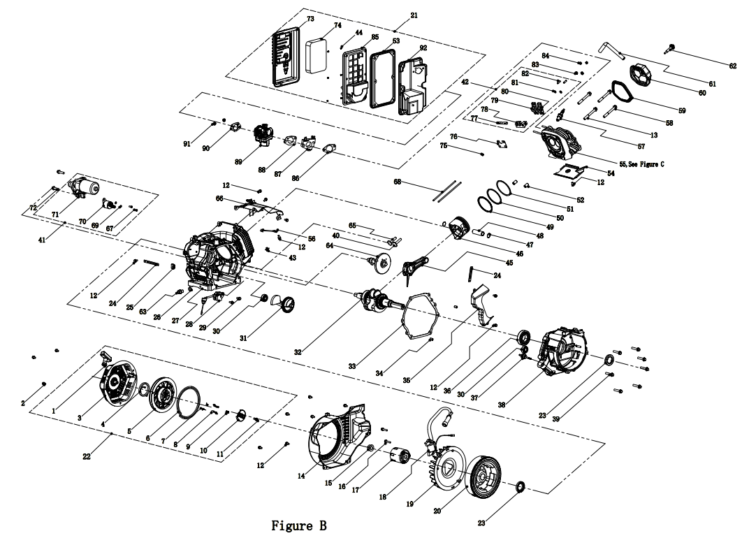
ENGINE PARTS LIST
| # | Part Number | Description | Qty. |
| 1 | 21.061300.00 | Handle, Recoil, Soft | 1 |
| 2 | 1.5789.0608 | Flange Bolt M6 x 8 | 3 |
| 3 | 46.061100.00.2 | Cover, Recoil Starter, Black | 1 |
| 4 | 45.060005.00 | Spring, Recoil Starter | 1 |
| 5 | 45.061102.00 | Reel, Recoil Starter | 1 |
| 6 | 2.10.003.1 | Rope 04 x 1550, Black | 1 |
| 7 | 45.060003.00 | Spring, Ratchet | 2 |
| 8 | 45.060002.00 | Starter Ratchet, Steel | 2 |
| 9 | 45.060009.00 | Spring, Ratchet Guide | 1 |
| 10 | 45.060007.00 | Ratchet Guide | 1 |
| 11 | 45.060008.00 | Screw, Ratchet Guide | 1 |
| 12 | 1.5789.0612 | Flange Bolt M6 x 12 | 13 |
| 13 | 2.08.174 | Flange Bolt M12 x 95 | 2 |
| 14 | 47.080100.01.48 | Fan Cover, Yellow | 1 |
| 15 | 2/2/1907 | Nut M16 x 1.5 | 1 |
| 16 | 1.5789.0620 | Flange Bolt M6 x 20 | 2 |
| 17 | 45.060001.00 | Pulley, Starter | 1 |
| 18 | 191.123000.00 | Ignition Coil With RPM Sensor | 1 |
| 19 | 48.080001.00 | Cooling Fan | 1 |
| 20 | 191120100.00 | Flywheel | 1 |
| 21 | 191.091000.00.2 | Air Cleaner Assembly | 1 |
| 22 | 46.061000.00 | Recoil Assembly | 1 |
| 23 | 2/11/1907 | Oil Seal 035 x 052 x 8 | 2 |
| 24 | 2/5/1950 | Wire Clip, 100 mm | 2 |
| 25 | 152.070031.01 | Sheath, Wire | 1 |
| 26 | 2/3/1923 | Washer 012.5 x 020 x 2, Drain Bolt | 1 |
| 27 | 191.030100.00 | Crankcase | 1 |
| 28 | 45.127000.00 | Oil Level Sensor | 1 |
| 29 | 1.5789.0615 | Flange Bolt M6 x 15 | 2 |
| 30 | 1.276.6202 | Bearing 6202 | 2 |
| 31 | 48.050006.00 | Weight Balancer | 1 |
| 32 | 47.050100.51 | Crankshaft | 1 |
| 33 | 46.030008.00 | Gasket, Crankcase Cover | 1 |
| 34 | 2/4/1901 | Dowel Pin 09 x 14 | 2 |
| 35 | 46.080600.00 | Air Guide, Right Side | 1 |
| 36 | 1.276.6207.9 | Bearing TM6207 | 1 |
| 37 | 46.031000.01.48 | Oil Dipstick Assembly, Yellow | 1 |
| 38 | 191.030007.00 | Cover, Crankcase | 1 |
| 39 | 1.5789.0840 | Flange Bolt M8 x 40 | 7 |
| 40 | 45.040013.00 | Lifter, Exhaust Valve | 1 |
| 41 | 45.125000.03 | Starter Motor Assembly | 1 |
| 42 | 46.040200.00 | Rocker Arm Assembly | 1 |
| 43 | 2/5/1905 | Clamp 06 | 1 |
| 44 | 1.6177.1 | Flange Nut M5 | 6 |
| 45 | 47.050200.00 | Connecting Rod | 1 |
| 46 | 48.050005.00 | Piston | 1 |
| 47 | 2/9/1904 | Circlip 021 x 01 | 2 |
| 48 | 45.050003.00 | Pin, Piston | 1 |
| 49 | 48.050303.00 | Ring, Oil | 1 |
| 50 | 48.050302.00 | Ring, Second Piston | 1 |
| 51 | 48.050301.00 | Ring, First Piston | 1 |
| 52 | 2/4/1904 | Dowel Pin 012 x 20 | 2 |
| 53 | 45.091002.20 | Seal, Air Cleaner | 1 |
| 54 | 46.080400.01 | Air Guide, Lower | 1 |
| 55 | 191.010000.00 | Cylinder Head Assembly – See Figure C | 1 |
| 56 | 5.1900.111 | Sensor, Engine Temperature | 1 |
| 57 | 2/15/1908 | Spark Plug F7RTC | 1 |
| 58 | 2.08.122 | Flange Bolt M10 x 95 | 2 |
| 59 | 46.020002.01 | Gasket, Cylinder Head Cover | 1 |
| 60 | 47.021000.01 | Cover, Cylinder Head | 1 |
| # | Part Number | Description | Qty. |
| 61 | 45.020001.03 | Breather Tube | 1 |
| 62 | 47020100.00 | Bolt, Cylinder Head Cover | 1 |
| 63 | 2/8/1939 | Drain Bolt M12 x 1.5 x 15 | 1 |
| 64 | 48.041000.00 | Camshaft | 1 |
| 65 | 48.040013.00 | Lifter, Intake Valve | 1 |
| 66 | 191.080300.00 | Air Guide, Upper | 1 |
| 67 | 1.16674.0516 | Flange Bolt M5 x 16 | 2 |
| 68 | 46.040005.00 | Push Rod | 2 |
| 69 | 1.93.05 | Lock Washer 05 | 2 |
| 70 | 45.125200.03 | Relay, Starter, Three Gear | 1 |
| 71 | 45.125100.00 | Starter Motor | 1 |
| 72 | 1.5789.0835 | Flange Bolt M8 x 35 | 2 |
| 73 | 191.091200.00 | Cover, Air Cleaner | 1 |
| 74 | 45.091003.20 | Element Air Cleaner | 1 |
| 75 | 45.040008.00 | Rotator, Exhaust Valve | 1 |
| 76 | 46.040004.00 | Guide Plate, Push Rod | 1 |
| 77 | 46.040016.00 | Shaft, Rocker Arm | 1 |
| 78 | 46.040201.00 | Retainer, Rocker Arm | 1 |
| 79 | 46.040009.00 | Rocker Arm, Intake Valve | 1 |
| 80 | 46.040018.00 | Rocker Arm, Exhaust Valve | 1 |
| 81 | 1.97.1.06 | Washer 06 | 2 |
| 82 | 22.040012.00 | Screw, Valve Adjustment | 2 |
| 83 | 1.61771.06 | Flange Nut M6 | 2 |
| 84 | 21.040021.00 | Nut M6 x 0.5, Lock | 2 |
| 85 | 45.091001.20 | Separator, Air Cleaner | 1 |
| 86 | 46.130002.20 | Gasket, Insulator | 1 |
| 87 | 45.130001.00 | Insulator, Throttle Body | 1 |
| 88 | 46.130003.20 | Gasket, Throttle Body | 1 |
| 89 | 191.130000.00 | Throttle Body | 1 |
| 90 | 46.130004.20 | Gasket, Air Cleaner | 1 |
| 91 | 1.6177.06 | Flange Nut M6 | 2 |
| 92 | 191.091100.00 | Base, Air Cleaner | 1 |
CYLINDER HEAD DIAGRAM
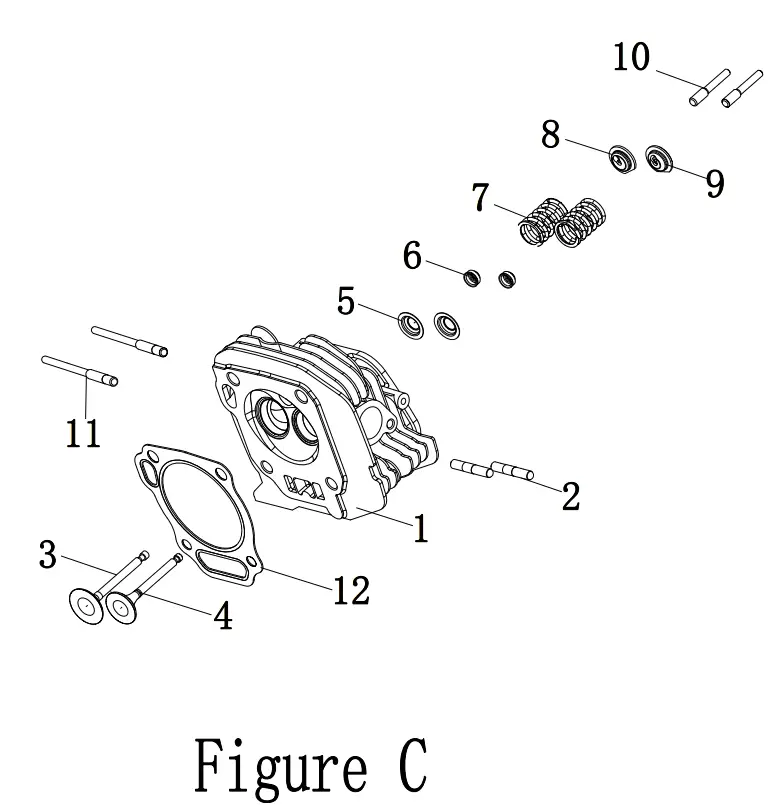
CYLINDER HEAD LIST
| # | Part Number | Description | Qty. |
| 1 | 191.010100.00 | Cylinder Head | 1 |
| 2 | 2/1/1910 | Stud Bolt M8 x 35 | 2 |
| 3 | 47.040002.00 | Valve, Intake | 1 |
| 4 | 47.040006.00 | Valve, Exhaust | 1 |
| 5 | 45.040015.00 | Retainer, Valve Spring | 2 |
| 6 | 45.040017.00 | Oil Seal, Valve | 2 |
| 7 | 45.040003.00 | Spring, Valve | 2 |
| 8 | 45.040001.00 | Retainer, Intake Valve Spring | 1 |
| 9 | 45.040007.00 | Retainer, Exhaust Valve Spring | 1 |
| 10 | 23.040010.00 | Bolt, Rocker Arm | 2 |
| 11 | 2/1/1908 | Stud Bolt M6 x M8 x 105 | 2 |
| 12 | 191.030009.00 | Gasket, Cylinder Head | 1 |
ALTERNATOR PART DIAGRAM
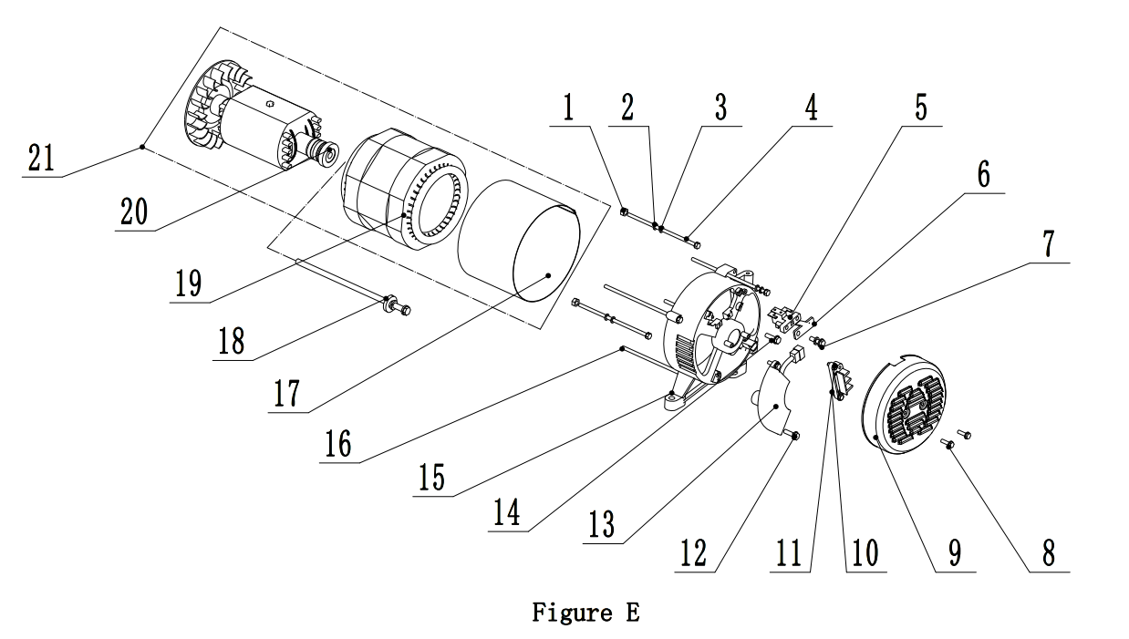
ALTERNATOR PART LIST
| # | Part Number | Description | Oty. |
| 1 | 1.6175.05 | Nut M5 | 2 |
| 2 | 1.97.1.05 | Washer 05 | 2 |
| 3 | 1.93.05 | Lock Washer 05 | 2 |
| 4 | 2/8/1971 | Bolt M5 x 229 | 2 |
| 5 | 152.190300.00 | Carbon Brush Assembly | 1 |
| 6 | 122.190004.01 | Bracket, Carbon Brush Retaining | 1 |
| 7 | 1.9074.15.0520 | Bolt/Washer Assembly M5 x 20 | 1 |
| 8 | 1.16674.0512.1 | Flange Bolt M5 x 12, Black | 2 |
| 9 | 152.190003.00.48 | Cover, End Housing, Yellow | 1 |
| 10 | 1.9074.17.0516 | Screw/Washer Assembly M5 x 16 | 2 |
| 11 | 122.190400.00 | Terminal Block | 1 |
| 12 | 1.16674.0516 | Flange Bolt M5 x 16 | 2 |
| 13 | 153190200. | AVR | 1 |
| 14 | 1.16674.0512 | Flange Bolt M5 x 12 | 1 |
| 15 | 152.190002.00 | End Housing | 1 |
| 16 | 2/8/1969 | Flange Bolt/Washer Assembly M6 x 194 | 4 |
| 17 | 154.191002.00 | Stator Cover | 1 |
| 18 | 2/8/1970 | Flange Bolt/Washer Assembly M10 x 280 | 1 |
| 19 | 155.191200.06 | Stator Assembly, Cu, 0204 x 158 mm, CSA | 1 |
| 20 | 155.191100.00 | Rotor Assembly, Cu, 0204 x 158 mm, CSA | 1 |
| 21 | 155.191000.06 | Alternator Assembly, Cu, 0204 x 158 mm, CSA | 1 |
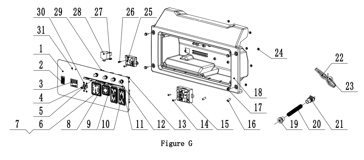
CONTROL PANEL PART DIAGRAM
CONTROl PANEL PART LIST
| # | Part Number | Description | city. |
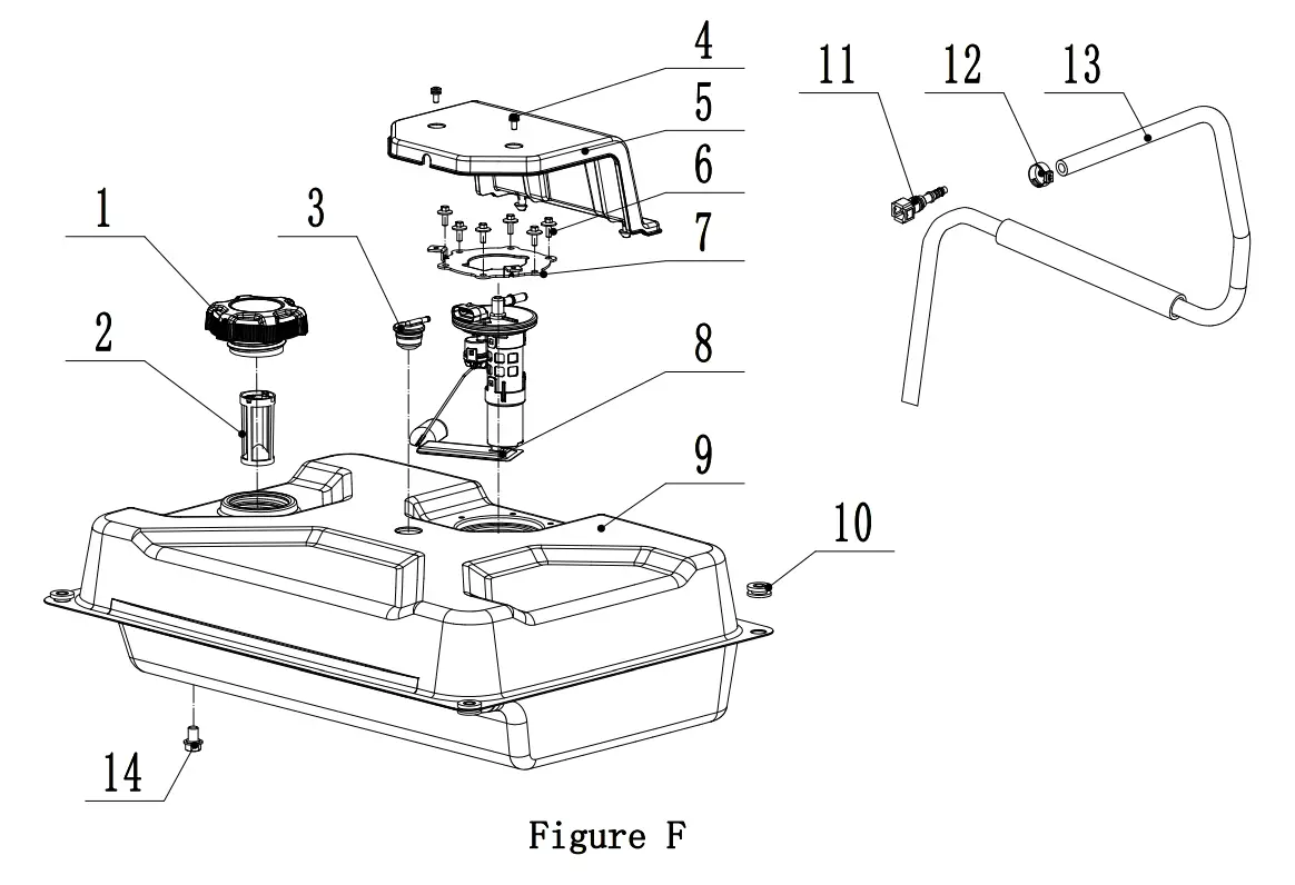
| 1 | 122.070100.09 | Fuel Tank Cap | 1 |
| 2 | 122.070300.03 | Fuel Filter | 1 |
| 3 | 24.070800.00 | Reversal Valve | 1 |
| 4 | 1.9074.4.0512.1 | Screw/Washer Assembly, M5 x 12, Black | 2 |
| 5 | 152.070008.03 | Cover, Fuel Pump | 1 |
| 6 | 2.08.068.2 | Flange Bolt, M5 x 13 | 6 |
| 7 | 191.070046.00 | Plate, Fuel Pump Retainer | 1 |
| 8 | 191.075000.00 | Fuel Pump | 1 |
| 9 | 152.071000.49.48 | Fuel Tank, 29L, Yellow | 1 |
| 10 | 122.070015.01 | Mount Vibration, Fuel Tank | 4 |
| 11 | 191.070600.00 | Connect, Fuel Pump | 1 |
| 12 | 2/6/1948 | Clamp, Oil Hose | 1 |
| 13 | 191.070011.00 | Tube, Fuel Supply, 850 mm | 1 |
| 14 | 2.08.172 | Flange Bolt Assembly M10 x 15 | 1 |
FUEL TANK PART DIAGRAM
FUEL TANK PARTLIST
| # | Part Number | Description | QTY. |
| 1 | 152.2991.2 | Control Panel | 1 |
| 2 | 5.1000.007.3 | Ignition Switch, Red | 1 |
| 3 | 5.1440.011 | Intelligence | 1 |
| 4 | 5.1240.380 | 38Amp Circuit Breaker, Double Pole | 1 |
| 5 | 5.1870.024 | Receptacle Cover, Receptacle 14-50R | 1 |
| 6 | 5.1120.044 | Receptacle 14-50R | 1 |
| 7 | 1.6177.1.04.1 | Lock Nut M4, Flange, Black | 8 |
| 8 | 5.1870.020 | Receptacle L14-30R | 1 |
| 9 | 5.1120.009 | Receptacle Cover, Receptacle L14-30R | 1 |
| 10 | 5.1120.050 | Receptacle 5-20R, Duplex GFCI | 2 |
| 11 | 5.1870.022 | Receptacle Cover, Receptacle 5-20R, Duplex GFCI | 2 |
| 12 | 5.1870.014 | Circuit Breaker Cover, Push Button | 4 |
| 13 | 5.1210.920 | 20Amp Circuit Breaker, Push Button, CSA | 2 |
| 14 | 1.845.4216 | Screw, ST4.2 x 16 | 2 |
| 15 | 5.1820.011 | Charger, 5A | 1 |
| 16 | 5.1280.003 | Fuse, 10A | 2 |
| 17 | 1.5789.0615.1 | Flange Bolt M6 x 15, Black | 4 |
| 18 | 152.210002.43 | Control Panel Housing | 1 |
| 19 | 122.210003.01 | Wire Jacket, Control Box | 1 |
| 20 | 5.1330.116 | Sheath, Wire | 1 |
| 21 | 152.210003.02 | Plug, Control Box | 1 |
| 22 | 100485.2110 | Wire Harness | 1 |
| 23 | 5.210400.00 | Current Transformer | 1 |
| 24 | 1.61771.05 | Flange Lock Nut M5, Black | 6 |
| 25 | 5.1830.026 | CO Module | 1 |
| 26 | 1.845.4213 | Screw, ST4.2 x 13 | 2 |
| 27 | 1.818.0514.2 | Screw M5 x 14 | 1 |
| 28 | 5.1810.008 | OVP Diode | 1 |
| 29 | 5.1210.930 | 30Amp Circuit Breaker, Push Button, CSA | 2 |
| 30 | 1.9074.4.0306.1 | Screw/Washer Assembly M3 x 6, Black | 4 |
| 31 | 5.1460.019 | Module, CO Shutdown LED | 1 |
FRAME PART DIAGRAM
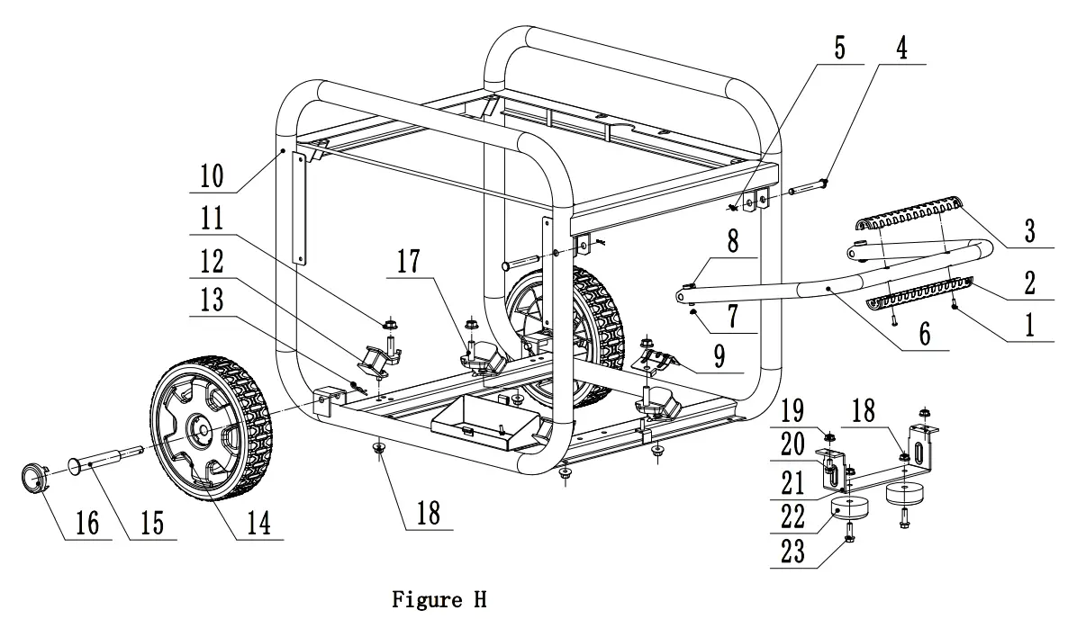
FRAME PART LIST
| # | Part Number | Description | city. |
| 1 | 1.818.0414.1 | Screw M4 x 14, Black | 2 |
| 2 | 122.200702.13 | Cover, Handle, Upper | 1 |
| 3 | 122.200702.14 | Cover, Handle, Lower | 1 |
| 4 | 152.200703.03 | Long Pin, Handle | 2 |
| 5 | 11.110008.00 | “R” Shape | 2 |
| 6 | 152.200701.23.2 | Handle, U Shape | 1 |
| 7 | 1.894.1.08 | Circlip 08 | 2 |
| 8 | 152.200703.02 | Short Pin, Handle | 2 |
| 9 | 152.100007.00 | Heat Shield, Motor Mount | 1 |
| 10 | 65306.010.2 | Frame,700 x 541 x 600 | 1 |
| 11 | 1.61771.10 | Lock Nut M10, Flange | 4 |
| 12 | 152.201200.03 | Vibration Mount 1 | 2 |
| 13 | 2.16.001.1 | Pin 02 x 33, “R” Shape, Black | 2 |
| 14 | 152.201701.13.48 | 9.5 in. Wheel, PU, Yellow | 2 |
| 15 | 122.201501.25.1 | Pin Roll, Wheel, 016 x 010 x 97, Black | 2 |
| 16 | 122.201702.11.48 | Wheel Cover, Tooth Profile 8-10 in, Yellow | 2 |
| 17 | 152.201200.04 | Vibration Mount 2 | 2 |
| 18 | 1.61771.08 | Flange Lock Nut M8 | 6 |
| 19 | 1.6177.1.08.1 | Flange Lock Nut M8, Black | 2 |
| 20 | 1.5789.0816.1 | Flange Bolt M8 x 16, Blcak | 2 |
| 21 | 152.200002.01.2 | Support Leg 84 mm | 1 |
| 22 | 152.201400.00 | Rubber, Support | 2 |
| 23 | 1.5789.0825 | Flange Bolt M8 x 25 | 2 |
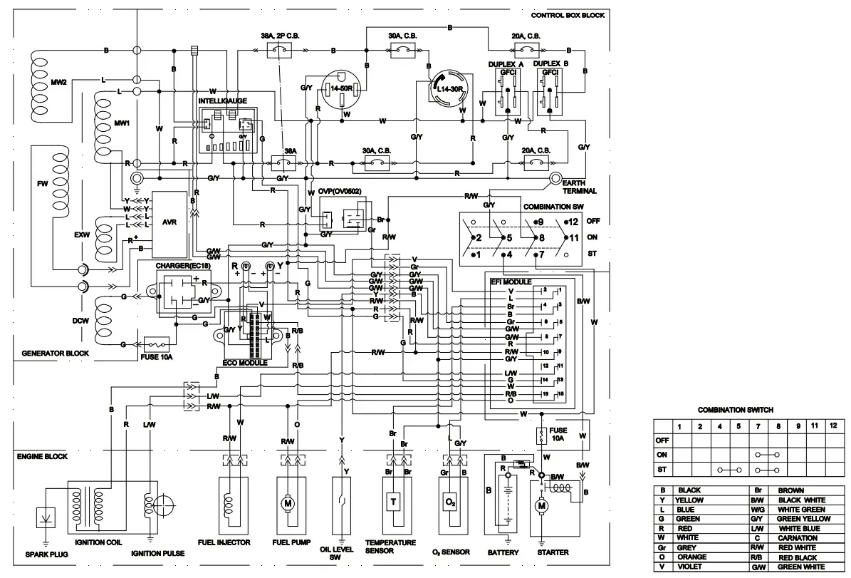
WIRING DIAGRAM
References
[xyz-ips snippet=”download-snippet”]