CHAMPION Automatic Transfer Switch with aXis Controller Module Installation Guide
![]() READ AND SAVE THIS MANUAL.This manual contains important safety precautions which should be read and understood before operating the product. Failure to do so could result in serious injury. This manual should remain with the product.Specifications, descriptions and illustrations in this manual are as accurate as known at the time of publication, but are subject to change without notice.
READ AND SAVE THIS MANUAL.This manual contains important safety precautions which should be read and understood before operating the product. Failure to do so could result in serious injury. This manual should remain with the product.Specifications, descriptions and illustrations in this manual are as accurate as known at the time of publication, but are subject to change without notice.
INTRODUCTION
Congratulations on your purchase of a Champion Power Equipment (CPE) product. CPE designs, builds, and supports all of our products to strict specifications and guidelines. With proper product knowledge, safe use, and regular maintenance, this product should bring years of satisfying service.
Every effort has been made to ensure the accuracy and completeness of the information in this manual at the time of publication, and we reserve the right to change, alter and/or improve the product and this document at any time without prior notice.
CPE highly values how our products are designed, manufactured, operated, and serviced as well as providing safety to the operator and those around the generator. Therefore, it is IMPORTANT to review this product manual and other product materials thoroughly and be fully aware and knowledgeable of the assembly, operation, dangers and maintenance of the product before use. Fully familiarize yourself, and make sure others who plan on operating the product fully familiarize themselves too, with the proper safety and operation procedures before each use. Please always exercise common sense and always err on the side of caution when operating the product to ensure no accident, property damage, or injury occurs. We want you to continue to use and be satisfied with your CPE product for years to come.
When contacting CPE about parts and/or service, you will need to supply the complete model and serial numbers of your product.Transcribe the information found on your product’s nameplate label to the table below.
CPE TECHNICAL SUPPORT TEAM
- 1-877-338-0999
MODEL NUMBER
- 102006, 102007, 102008, 102009, 102010
SERIAL NUMBERDATE OF PURCHASEPURCHASE LOCATION
SAFETY DEFINITIONS
The purpose of safety symbols is to attract your attention to possible dangers. The safety symbols, and their explanations, deserve your careful attention and understanding. The safety warnings do not by themselves eliminate any danger. The instructions or warnings they give are not substitutes for proper accident prevention measures.
DANGER
DANGER indicates a hazardous situation which,if not avoided, will result in death or serious injury.
WARNING
WARNING indicates a hazardous situation which, if not avoided, could result in death or serious injury.
CAUTION
CAUTION indicates a hazardous situation which, if not avoided, could result in minor or moderate injury.
NOTICE
NOTICE indicates information considered important, but not hazard-related (e.g., messages relating to property damage).
IMPORTANT SAFETY INSTRUCTIONS
WARNING
Cancer and Reproductive Harm – www.P65Warnings.ca.gov
Instructions for Champion Automatic Transfer Switch with aXis ControllerTM Module
THE CHAMPION AUTOMATIC TRANSFER SWITCH WITH aXis CONTROLLERTM MODULE IS NOT FOR “DO-IT-YOURSELF” INSTALLATION. It must be installed by a qualified electrician thoroughly familiar with all applicable electrical and building codes.
This manual has been prepared for familiarizing servicing dealer/ installer with the design, application, installation and servicing of the equipment.
Read the manual carefully and comply with all instructions.
This manual or a copy of this manual should remain with the switch. Every effort has been taken to make sure that the contents of this manual are accurate and current.
The manufacturer reserves the right to change, alter or otherwise improve this literature and the product at any time without prior notice and without any obligation or liability whatsoever.
The manufacturer cannot anticipate every possible circumstance that might involve a hazard.
The warnings in this manual, tags and decals affixed to the unit are, therefore, not all-inclusive. If using a procedure, work method or operating technique the manufacturer does not specifically recommend follow all codes to ensure safety for personnel.
Many accidents are caused by failing to follow simple and fundamental rules, codes and precautions. Before installing, operating or servicing this equipment, read the SAFETY RULES carefully.
The publications that cover the safe use of ATS and installation are the following NFPA 70, NFPA 70E, UL 1008 and UL 67. It is important to refer to the latest version of any standard/code to ensure correct and current information. All installations must comply with local municipal, state and national codes.
Before Installation
WARNING
Per OSHA 3120 Publication; “lockout/tagout” refers to specific practices and procedures to safeguard individuals from the unexpected energization or startup of machinery and equipment, or the release of hazardous energy during installation, service or maintenance activities
DANGER
Be certain that the power from the utility is turned off and all backup sources are locked out before starting this procedure.Failure to do so could result in serious injury or death. Be aware, automatic start generators will start upon loss of utility mains power unless locked in the “off” position.Consult the generator operator manual section to locate the ATS CONTROL and ENGINE CONTROL modules to make sure both switches are in the OFF position.
CAUTION
Consult with your Local municipal, State and National electrical codes for proper mandatory wiring methods.
Safety Labels
These labels warn you of potential hazards that can cause serious injury. Read them carefully.If a label comes off or becomes hard to read, contact Technical Support Team for possible replacement.
HANGTAG/LABEL
ATTENTIONALTERNATE POWER SOURCE AVAILABLE – STANDBY GENERATOR ON PREMISES.
GENERATOR LOCATION
DO NOT REMOVE
CAUTION : This switch will not transfer if over current device opens due to fault.
DANGER
- Electrical shock hazard. May cause injury or death.
- Disconnect all sources of supply before servicing.
WARNING
More than one live circuit – disconnect all sources of supply before servicing.
DESCRIPTION
- Alternate Power Source
- Caution. Over current device.
- Danger. Electrocution shock hazard.
- Warning. More than one live circuit.
Safety Symbols
Some of the following symbols may be used on this product. Please study them and learn their meaning. Proper interpretation of these symbols will allow you to more safely operate the product.
| SYMBOL | MEANING |
 |
Read Installation Manual. To reduce the risk of injury, user must read and understand installation manual before using this product. |
 |
Ground. Consult with local electrician to determine grounding requirements before operation |
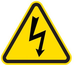 |
Electric Shock. Improper connections can create an electrocution hazard |
CONTROLS AND FEATURES
Read this installation manual before installing your transfer switch. Familiarize yourself with the location and function of the controls and features. Save this manual for future reference.
Champion Automatic Transfer Switch with aXis ControllerTM Module

- aXis Controller
- Antenna
- Generator L1 and L2 Terminals
- Battery Charger Fuse Block
- Two Wire Sensing Fuse Block – Used only with a nonChampion HSB
- Ground Bar
- Neutral Bar
- Neutral to Ground Bonding Wire
- Load L1 and L2 Terminals
- Utility L1 and L2 Terminals
- Mounting Holes
- Front Cover
- Dead Front
- Utility Access Panel (if applicable
UNPACKING
- Use care when unpacking to avoid damaging transfer switch components.
- Allow the ATS to acclimate to room temperature for a minimum of 24 hours before unpacking to prevent condensation on the electrical apparatus.
- Use a wet/dry vacuum cleaner or a dry cloth to remove dirt and packing material that may have accumulated in the transfer switch or any of its components during storage.
- Do not use compressed air to clean the switch, cleaning with compressed air can cause debris to lodge in the components and damage the switch per the ATS manufacturers specifications.
- Retain the ATS manual with or near the ATS for future reference.
| TOOLS REQUIRED | NOT INCLUDED |
| 5/16 in. Hex Wrench | Mounting Hardware |
| Line Voltage Wire | |
| 1/4 in. Flat Screwdriver | Conduit |
| Fittings |
Location and Mounting
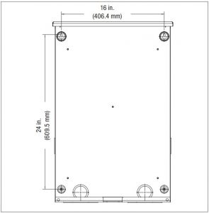
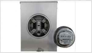
Install the ATS as close as possible to utility meter socket. Wires will run between the ATS and main distribution panel, proper installation and conduit are required by code. Mount the ATS vertically to a rigid supporting structure. To prevent the ATS or enclosure box from distortion, level all mounting points; use washers behind the mounting holes (outside the enclosure, between enclosure and supporting structure), see following image.The recommended fasteners are 1/4” lag screws. Always follow local code.
Electrical Grommet(s)
Grommets can be used in any enclosure knockout for NEMA 1 installations. Grommets can only be used in the bottom enclosure knockouts for NEMA 3R installations, when installed outside.
Installation Wiring for ATS Utility Socket
WARNING
- The manufacturer recommends that a licensed electrician or an individual with complete knowledge of electricity perform these procedures.
- Always be certain that the power from the main panel is turned “OFF” and all backup sources are locked out prior to removal of the cover or removal of any wiring of the utility main electrical distribution panel.
- Be aware, automatic start generators will start upon loss of utility main power unless locked in the “OFF” position.
- Failure to do so could result in serious injury or death.
CAUTION
Consult with your Local municipal, State and National electrical codes for proper mandatory wiring methods.
Conductor sizes must be adequate to handle the maximum current to which they will be subjected. The installation must comply fully with all applicable codes, standards and regulations. Conductors must be properly supported, of approved insulation materials, protected by approved conduit and with the correct wire gauge size in accordance with all applicable codes. Before connecting wire cables to terminals, remove any surface oxides from the cable ends with a wire brush. All power cables must enter the enclosure through the enclosure knockouts.
- Determine where the flexible, liquid tight conduit will pass through the building from the inside to outside. When you are certain that there is adequate clearance on each side of the wall, drill a small pilot hole through the wall to mark the location. Drill an appropriate sized hole through the sheathing and siding.
- In compliance with all local electrical codes, route the conduit along ceiling/floor joists and wall studs to the location where the conduit will pass through the wall to the exterior of the house. Once the conduit is pulled through the wall and in proper position to attach to the HSB generator, place silicone caulk around the conduit on both side of the hole, inside and outside.
- Mount the ATS near the Utility meter socket.
Wiring the ATS
NOTICE
US ATS model shown for reference. For Canadian installation, refer to ATS Installation Manual.
NOTICE
The aXis ATS controls the automatic startup and shutdown of the aXis HSB using Power Line Communication (PLC).The PLC system utilizes the L1 and L2 power wires that run between the ATS and HSB for communication. As a result, there are no wires that need to be run between the ATS and HSB besides the power wires (L1, L2, N, G) and battery charger wires mentioned in this manual.
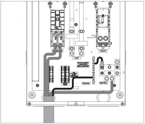
- Have authorized utility personnel pull the utility meter from the meter socket.

- Remove door and dead front of ATS.
- Connect Utility (L1-L2) to ATS Utility side breaker. Torque to 275 in-lbs.
- Connect Utility N to Neutral lug. Torque to 275 in-lbs.
- Connect earth GROUND to GROUND bar. NOTE: GROUND and NEUTRAL bonded in this panel.
- Connect Generator L1-L2 to Generator side breaker. Torque to 45-50 in-lbs.
- Connect Generator Neutral to neutral bar. Torque to 275 in-lbs.
- Connect Generator Ground to ground bar. Torque to 35-45 in-lbs.
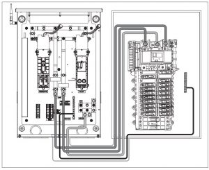
- Connect Load bars L1 and L2 to distribution panel. Torque to 275 in-lbs.
- Pull NEUTRAL from ATS to distribution panel. Pull GROUND from ATS to distribution panel.

CAUTION
- Remove bond from distribution panel if installed.
Battery Charger Wiring
The aXis Controller™ HSB contains a 24V battery charger that is powered by 120V AC. The battery charger receives 120V AC power from the aXis Controller™ ATS using the single fuse block located in the bottom left corner of the ATS.
- Run two wires from the ATS to the HSB for the battery charger circuit.The battery charger circuit is 120V AC, 1 amp maximum. Wires need to be sized accordingly.Wiring can run in the same conduit as the L1, L2, Neutral and Ground wires from the previous section provided:
- Battery charger wire has an insulation rating equal to or greater than 264VAC.
- Battery charger wire is suitable for outdoor installation.
- Allowed by local code and meets NFPA 70.
- ATS Connections for battery charger.
- L1 – Bottom terminal of the fuse block in the ATS.
- Neutral – Neutral block.See picture below for location of fuse block and neutral block.
- HSB Connection for battery terminals
- L1 and N will connect to a terminal located near the connection points of L1, L2, N, and G. Refer to aXis controller™ HSB installation manual for more information.

Utility Sensing Fuse Block
The utility sensing fuse block is not used in a typical installation.The fuse block is only used when connecting the Champion aXis ATS to a non-Champion HSB that monitors utility voltage to control automatic generator start/stop. The potential voltage between the two fuses is 240V AC
Do not use the utility sensing block for the battery charging circuit. The battery charging fuse block is located next to the utility sensing fuse block.
INSTALLATION
Low Voltage Control Relays
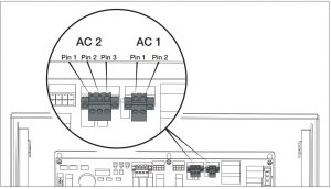
The aXis ControllerTM ATS has two low voltage relays that can be used to manage the load of air conditioners or other devices that utilize low voltage controls. The ATS’s two low voltage relays are called AC1 and AC2 and are found on the aXis control board as shown in the picture below.
Settings on the aXis ControllerTM Module
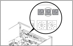
- On the aXis control board, set the two circular pots that are located to the right of the DIP switches to match the maximum power output of the generator for your fuel type.1st pot (left pot) is 10’s value, 2nd pot (right pot) is 1’s value, do not go over generator rating. If wattage rating of generator falls between settings choose the next lower value; i.e. generator rating is 12,500W, set pots to 1 and 2 for 12,000W.NOTICEAll DIP switches are set to ON by default from the factory except for switch #9 which is set to OFF.
- Verify the DIP switches are set for your installation. Adjust as needed.
 NOTICEAll DIP switches are set to ON by default from the factory except for switch #9 which is set to OFF.
DIP Switch Settings
Switch 1. Load Module 1 Lockout
- On= Load Module 1 is being managed. Load Module 1 is the lowest priority of the 4 load modules. This load will be turned off first as the ATS manages the home’s load.
- Off= Load module 1 will stay off during HSB power
Switch 2. Load Module 2 Lockout
- On= Load Module 2 is being managed.
- Off= Load module 2 will stay off during HSB power
Switch 3. Load Module 3 Lockout
- On= Load Module 3 is being managed.
- Off= Load module 3 will stay off during HSB power.
Switch 4. Load Module 4 Lockout
- On= Load Module 4 is being managed. Load Module 4 is the highest priority of the 4 load modules. This load will be turned off last as the ATS manages the homes load.
- Off= Load module 4 will stay off during HSB power.
Switch 5. Frequency Protection.
- On= All managed loads will be turned off when if the HSB frequency drops below 58 Hz.
- Off= All managed loads will be turned off when if the HSB frequency drops below 57 Hz.
Switch 6. Spare. Not used at this time. Switch position does not matter.
Switch 7. Power Management
- On= ATS is managing the homes load.
- Off= ATS has disabled power management.
Switch 8. PLC vs. Two Wire Communication
- On= ATS will control HSB startup and shutdown through PLC.This is the preferred method of communication however it requires the HSB to be an aXis controlled HSB.
- Off= ATS will control the start of the HSB using the AC2 Relay. In this setting the AC2 can not be used to manage a load. Pins 1 and 3 of the AC2 connector will be used for the HSB startup signal.
Switch 9. Test HSB with Load
- On= Test occurs with load.
- Off= Test occurs without load.
Switch 10. Master/Slave
- On= This ATS is the primary or only ATS. <- most common.
- Off= This ATS is being controlled by a different aXis controller™ ATS. Used for installations that require two ATS boxes (i.e. 400A installations).
Switch 11. Exercise Test
- On= Exercise tests will occur per the schedule that is programmed into the aXis controller.
- Off= Exercise tests are disabled.
Switch 12. Time delay for HSB to accept load.
- On= 45 seconds.
- Off= 7 seconds
- Have authorized utility personnel reconnect the utility meter to the meter socket.
- Verify voltage at utility circuit breaker.
- Turn on utility circuit breaker.
- ATS aXis ControllerTM module will begin boot up process. Allow ATS aXis ControllerTM module to fully boot up (approximately 6 minutes).
- Home should be fully powered at this point.
WIFI Setup Method
- . Use a WiFi enabled device (laptop, smart phone, tablet, etc.) in near proximity to the ATS.
- Search and Connect to network name (SSID) “ChampionXXXX” where XXXX will match the last four digits of the serial number that is printed on the control board. The password for the network is located on a decal on the dead front of the ATS.
- After connecting, open your device’s web browser. Many times the Champion aXis ControllerTM Home Standby Generator Settings Page will autoload however if that is not the case, refresh the browser or change the web address to anything.com. As your device attempts to reach the internet the WiFi module in the ATS will redirect your browser to the Champion aXis ControllerTM Home Standby Generator Settings Page.If the device’s web browser does not load the Champion aXis Controller™ Home Standby Generator Settings Page but rather stays connected to the internet, turn off mobile data on the device (if applicable) and make sure the device is not connected to any other networks.Note: During the setup the device will disconnect from the internet. The Champion WIFI is a direct connection between the device and the ATS and it does not connect to the internet.If the device is still not connecting, wait 2 minutes and try to connect with the web browser once again.
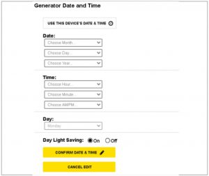
- On the Champion aXis ControllerTM Home Standby Generator Settings Page, set the date and time. Use either the dropdown boxes or the “USE THIS DEVICE’S DATE & TIME” button to set the time and date. Confirm and Save the settings before continuing.
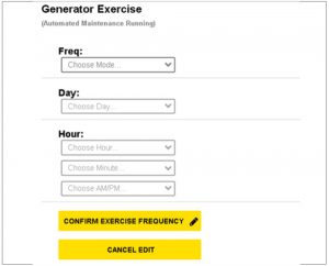
- Set the HSB exercise frequency and schedule. Confirm and Save the settings before continuing
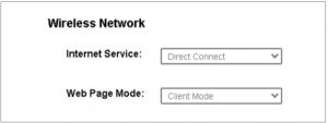
- Wireless network settings are not used at this time. The default values (shown below) should not be adjusted.
- The time, date, and exercise information have now been setup for the aXis ATS and HSB. You can close your browser and disconnect from the WIFI, or skip to step 2 in the next section “ATS & HSB STATUS USING WIFI”.
ATS and HSB Status Using WIFI
- Using a WIFI enabled device, connect to the “Champion HSB” WIFI network following steps 1, 2, and 3 from WIFI Setup Method.
- After loading the Home Standby Generator Settings page, locate and click the icon at the bottom right corner of the page.
- You are now viewing the ATS and HSB status page. Items such as voltage, frequency, current, etc. can all be viewed for both utility and HSB power. All of the information is live. There are three tabs located at the top of the page . ATS, GEN, and LMM. Each tab will display the status for the Transfer Switch, Home Standby Generator, or Load Management Module(s) respectively.
- When finished viewing the status of the ATS, Generator, and LMM, close your browser and disconnect from the WIFI.
Connecting the Load Management Systems
The following instructions pertain only to aXis ControllerTM Load Management Modules (LMM) that use Power Line Carrier (PLC)communication. If one or more LMM’s are being installed on the home, install them per the installation instructions included with the LMM before continuing.
Teaching System
After installation and wiring are complete teach the ATS which loads are attached by the following procedure. Teaching the system is only required if 1 or more LMM’s were installed OR if AC1 OR if AC2 is being used to manage loads.
- Turn Champion aXis ControllerTM ATS UTILITY circuit breaker to the OFF position. Generator will start and run automatically.
- Confirm managed loads are all operating.
- Press and hold the button marked “LEARN” for 8 seconds. ATS will shutoff managed loads one at a time until all are OFF. ATS will flash LED’s indicating function in process.
- After ATS has learned all loads the LMM units will be returned to normal operation.
- Installation configuration is now held in memory and will not be affected by power outage.
- Return UTILITY circuit breaker to the ON position. ATS will transfer load back to utility and generator will cool down and shut off.
- Repeat this process if LMM units are added or removed from the system.
Full System Check
- Open Utility breaker for full system test, close breaker after confirming all systems working.
- After Utility breaker opens engine will start automatically.
- aXis ATS control panel will reboot on Generator power and control switching of latching relays.
- Home is now powered by Generator. If Load Management modules (LMM) have been installed, they will become active after 5 minutes.
- Close Utility breaker
- System is now fully functional.
- Replace the dead front by sliding it from the bottom up into the cabinet; panel should index into the door latch protrusions. Secure it to the dead front bracket with included nut and stud.
- Replace the door and secure with included hardware. It is recommended to secure the door with a lock.
- Return to HSB and verify the controller is in “AUTO” mode. Confirm icons indicate Utility power is active, Utility side relay is closed, and home is receiving power.
- Close and lock HSB hoods return keys to customer.
NEMA 1 – This type of enclosed ATS is for indoor installations only.
NEMA 3R – This type of enclosed ATS is similar to the indoor box, except that it is a weatherproof enclosure and required for exterior installations by code. The enclosure only has knockouts on the bottom side for the enclosure, requires water tight fasteners/ grommets when installed outside per code. This enclosure can also be used inside.
SPECIFICATIONS
| Model | 102006 | 102007 | 102008 | 102009 | 102010 |
| Enclosure Style | NEMA 3R Outdoor | ||||
| Maximum Amps | 200 | 150 | 100 | ||
| Nominal Volts | 120/240 | ||||
| ETL Listed | UL STD NO. 1008 | CSA STD C22.2 No.
178.1 |
UL STD NO. 1008 | CSA STD C22.2 No. 178.1 | |
| Load Management Circuits | 4 | ||||
| Weight | 43 lbs (19.6 kg) | ||||
| Height | 28 in. (710 mm) | ||||
| Width | 20 in. (507 mm) | ||||
| Depth | 8.3 in. (210 mm) |
Technical Specifications
- 22kAIC, no short-time current rating.
- Suitable for use in accordance with the National Electrical Code, NFPA 70.
- Suitable for control of motors, electrical discharge lamps, tungsten filament lamps, and electrical heating equipment, where the sum of the motor full load ampere ratings and the ampere ratings of the other loads does not exceed the ampere rating of the switch, and the tungsten load does not exceed 30% of the switch rating.
- Continuous load not to exceed 80% of switch rating.
- Line voltage wiring: Cu or AL, min 60°C, min AWG 1 – max AWG 000, torque to 250 in-lb.
- Signal or Com Wiring: Cu only, min AWG 22 – max AWG 12, torque to 28-32 in-oz.
- All connection lugs are rated AL9CU – 90°C rated
NEMA 3R – This type of enclosed ATS is a weatherproof enclosure and required for exterior installations by code. The enclosure has knockouts on the bottom and side, and requires water tight connections when installed outside per code. This enclosure can also be used inside.
WARRANTY
Each Champion transfer switch or accessory is guaranteed against mechanical or electrical failure due to manufacturing defects for a period of 24 months following shipment from the factory.The manufacturer’s responsibility during this warranty period is limited to repair or replacement, free of charge, of products proving defective under normal use or service when returned to the factory, transportation charges prepaid. Guarantee is void on products that have been subjected to improper installation, misuse, alteration, abuse or unauthorized repair. The manufacturer makes no warranty with respect to the fitness of any goods for a user’s particular application and assumes no responsibility for proper selection and installation of its products. This warranty is in lieu of all other warranties, expressed or implied, and limits the manufacturer’s liability for damages to the cost of the product.This warranty gives you specific legal rights, and you may have other rights, which vary from state to state.
CHAMPION POWER EQUIPMENT 2 YEAR LIMITED WARRANTY
Warranty Qualifications
To register your product for warranty and FREE lifetime call center technical support please visit: https://www.championpowerequipment.com/register
To complete registration you will need to include a copy of the purchase receipt as proof of original purchase. Proof of purchase is required for warranty service. Please register within ten (10) days from date of purchase.
Repair/Replacement Warranty
CPE warrants to the original purchaser that the mechanical and electrical components will be free of defects in material and workmanship for a period of two years (parts and labor) from the original date of purchase and 180 days (parts and labor) for commercial and industrial use. Transportation charges on product submitted for repair or replacement under this warranty are the sole responsibility of the purchaser. This warranty only applies to the original purchaser and is not transferable.
Do Not Return The Unit To The Place Of Purchase
Contact CPE’s Technical Service and CPE will troubleshoot any issue via phone or e-mail. If the problem is not corrected by this method, CPE will, at its option, authorize evaluation, repair or replacement of the defective part or component at a CPE Service Center. CPE will provide you with a case number for warranty service. Please keep it for future reference. Repairs or replacements without prior authorization, or at an unauthorized repair facility, will not be covered by this warranty.
Warranty ExclusionsThis warranty does not cover the following repairs and equipment:
Normal Wear
Products with mechanical and electrical components need periodic parts and service to perform well. This warranty does not cover repair when normal use has exhausted the life of a part or the equipment as a whole.
Installation, Use and Maintenance
This warranty will not apply to parts and/or labor if the product is deemed to have been misused, neglected, involved in an accident,abused, loaded beyond the product’s limits, modified, installed improperly or connected incorrectly to any electrical component.Normal maintenance is not covered by this warranty and is not required to be performed at a facility or by a person authorized by CPE.
Other Exclusions
This warranty excludes
- Cosmetic defects such as paint, decals, etc.
- Wear items such as filter elements, o-rings, etc.
- Accessory parts such as storage covers.
- Failures due to acts of God and other force majeure events beyond the manufacturer’s control.
- Problems caused by parts that are not original Champion Power Equipment parts.
Limits of Implied Warranty and Consequential Damage
Champion Power Equipment disclaims any obligation to cover any loss of time, use of this product, freight, or any incidental or consequential claim by anyone from using this product. THIS WARRANTY IS IN LIEU OF ALL OTHER WARRANTIES, EXPRESS OR IMPLIED, INCLUDING WARRANTIES OF MERCHANTABILITY OR FITNESS FOR A PARTICULAR PURPOSE.
A unit provided as an exchange will be subject to the warranty of the original unit. The length of the warranty governing the exchanged unit will remain calculated by reference to the purchase date of the original unit.
This warranty gives you certain legal rights which may change from state to state or province to province. Your state or province may also have other rights you may be entitled to that are not listed within this warranty.
Contact Information
Address
Champion Power Equipment, Inc.12039 Smith Ave.Santa Fe Springs, CA 90670 USAwww.championpowerequipment.com
Customer Service
Toll Free: 1-877-338-0999[email protected]Fax no.: 1-562-236-9429
Technical Service
Toll Free: 1-877-338-0999[email protected]24/7 Tech Support: 1-562-204-1188

References
[xyz-ips snippet=”download-snippet”]