Chandler Limited REDD Microphone User Manual

Chandler Limited® REDD Microphone
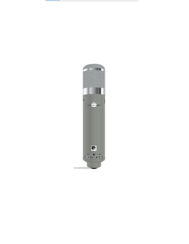
Thank you for purchasing the Chandler Limited REDD Microphone, you now own a piece of EMI / Abbey Road Studios official equipment.Continuing in the rich tradition of innovation at EMI, dating back to the early 1930s with Alan Blumlein, the father of ‘Stereo’, the company’s first coil microphones, velocity ‘ribbon’ mics and the “Blumlein pair” technique, Chandler Limited and Abbey Road Studios introduce the first new EMI badged microphone in over a half century, the ‘REDD Microphone’.Designed by Chandler Limited Founder and Chief Designer, Wade Goeke, the REDD Microphone [Patent No. 10,412,477] represents a shift in traditional microphone design, bringing together historic circuitry and the heralded EMI REDD.47 pre-amplifier sound in a new and unique way.The REDD Microphone is a large diaphragm tube condenser microphone, featuring a dedicated internal REDD.47 Mic Amplifier circuit.The REDD Microphone system includes: microphone, 7-pin microphone cable, power supply and AC cord, shock mount suspension apparatus, pattern select screwdriver, and custom moulded flight case.The REDD Microphone, featuring its on-board REDD.47 pre-amplifier circuit, is contained in a cylindrical metal assembly, directly coupled to a premium custom made, hand-milled, platinum membrane capsule, housed in the chrome head-basket compartment. The front of the microphone is distinguished by the Chandler Limited and Abbey Road Studios logos.The close proximity of capsule to microphone pre-amp provides the shortest possible distance between microphone capsule and pre-amplifier, allowing the REDD Microphone to drive the line from the source, rather than the end. The all-in-one approach reduces electronic circuitry in the audio path, and allows for high-gradeaudio transmission from the source.The REDD Microphone was designed to plug directly into audio interfaces or tape machines, however, can be used with traditional external pre-amplifiers for more tonal possibilities.We are proud of our American made products and we hope you like them!Call our shop anytime for help or questions. Phone: (319) 885-4200
HISTORY
In 1958, EMI and Abbey Road Studios, through their REDD (Record Engineering Development Department) technical division, designed the REDD.47 line amplifier as a plug-in line amplifier for their new REDD.51 consoles, replacing the Telefunken/Siemens V72s used in early REDD mixing consoles. The REDD.47 line amplifier was unique, both in design and sound from the V72s.The first REDD.51 console was manufactured in 1959. However, it wouldn’t be until 1964 before a REDD.51 console was installed at Abbey Road Studios’ Studio Two, home to The Beatles, leaving its exceptional sonic character on their recordings from 1964 to 1968.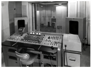
IMPORTANT QUICK START & POWER CYCLE PROCEEDURE
- Mount the microphone to a suitable microphone stand using the supplied shock mount suspension apparatus.
- PRIOR TO POWER-UP – CONNECTIONSa. Connect the microphone to power supply using the supplied 7-pin microphone cable.b. Connect the user supplied standard 3-pin XLR microphone cable to the audio interface or tape machine.c. Connect the power supply to an AC outlet.
- POWER-UPa. Once all connections to and from the power supply to the microphone have been made, turn on the power supply, by means of the power switch located at the rear of the PSU.b. If power has been achieved, the microphone’s on-board LED, located inside the head-basket, will illuminate red to signify the microphone is active. The LED is also used to help align the capsule to the sound source.c. WARNING- Do not disconnect the 7-Pin microphone cable while AC power is applied to the microphone. If disconnection is to be made, power down the microphone, and allow 5-10 minutes of cool-down time prior to disconnection of the 7-pin microphone cable from the power supply. NOTE- 3-pin XLR audio output connection may be patched or unpatched as necessary, without powering down.
- WARM-UP TIMEa. Prior to sound incident or usage, allow the microphone’s tubes to warm-up for a minimum of 10 minutes.
- POWER DOWNa. Prior to disconnecting the 7-pin cable, power down the PSU, and allow 5-10 minutes for the microphone’s internal tubes to cool down and the capsule adequate time to discharge. NOTE- It is recommended to power down the REDD Microphone when not in use.
ON-BOARD MICROPHONE CONTROLS PRE AMPLIFIER
The dedicated on-board REDD.47 Mic Amplifier (pre-amplifier) circuit provides the ability to use the REDD Microphone with or without the need for an externalpre-amp. The preamplifier and most of its available features are adjustable directly from the microphone body.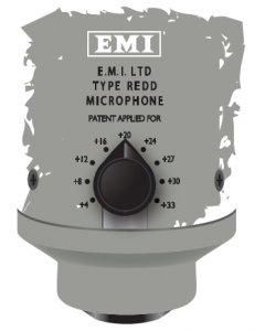
GAIN
The on-board microphone pre-amplifier gain setting is adjustable at the rear of the microphone. There’s nine gain settings to chose from, including:+4,8,12,16,24,27,30,33db. The resultant effective gain is also dependent upon the NORM’ vs ‘DRIVE’ mode setting; selection of either ‘NORM’ or ‘DRIVE’ mode is available via toggle switch from the front of the microphone body, and have a tonal effect on the microphone signal.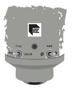
NORMWhen the toggle switch is set to ‘NORM,’ the REDD Microphone pre-amplifier is considered in its normal operational condition. The sound characteristic in thisstate, is more organic or natural, or laidback in comparison to ‘DRIVE’.
DRIVEThe ‘DRIVE’ setting has an overall effect over the adjustable gain range, both in terms of structure and more importantly, harmonic content. It is similar to the ‘FINE GAIN’ on the REDD.47 Mic Amplifier rack-mount counterpart, however, set fully on and non-variable. When set to the ‘DRIVE’ position, the tonal effect on the microphone signalis identifiable, characterized as being more immediate, punchy and present. The resultant tonal change is also interactive and dependent upon the gain setting.Depending upon the sound incident level and gain setting, ‘DRIVE’ mode, if driven hard enough, can impart wonderful harmonic coloration and tube saturation with alittle characteristic ‘hair’ on a signal.
POLEIn cases where phase continuity relative to other microphones in the environment is required, an 180º polarity reversal of the output signal is achieved by use of the ‘POLE’ or phase reverse toggle switch available from the microphone body.When the toggle is set outward, to the circular or ‘O’ designation, phase is in its natural position at 0º. Conversely, when the switch is positioned to the left at the ‘ø’ designation, phase is reversed 180º.
POLAR PATTERNS
The directional characteristic of the REDD Microphone is selectable. Two polar pattern options are provided, Cardioid or Omni-directional, either is available via toggle switch from the microphone body, using the supplied pattern select screwdriver.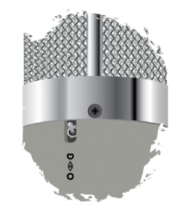
POLAR PATTERNS
This unidirectional polar pattern discriminates against source arriving at the rear of the capsule, and to a lesser degree at the sides, in preference for sound incident at the front of the microphone. Proximity effect is a natural occurrence of the Cardioid polar pattern, where low-end is emphasized when the sound source is closer to the microphone.TIP- If in Cardioid, the microphone is required to be placed in close proximity to a source, such as acoustic guitar, where capture of low frequency data is less desired, or in small environments where natural build-up can occur, use the ‘LOW-CONTOUR’ feature as an alternate microphone voicing; See ‘LOW-CONTOUR’ control section. If Cardioid is not required, and ‘LOW-CONTOUR’ is unnecessary, the Omni pattern can be used to diminish proximity effect.TIP- Use the Cardioid pattern in scenarios where minimal pickup at the rear of the microphone is needed.
OMNI
The omni-directional polar pattern is spherical, picking-up from all sides of the capsule, e.g. the pattern is indiscriminate to the direction of sound incident.Proximity effect is not a feature of the Omni pattern, and as a result, an apparent drop in lows (and gain,) is a normal byproduct of this setting.TIP- Use Omni where a sense of space is apropos, for example, strings, acoustic guitars, pianos or other material, or a more natural distribution of low-end is preferable.

PAD
Facility to decrease sensitivity of the microphone by -10db exists, and is made available from the microphone body via toggle of the PAD switch to the downwardposition, using the supplied pattern select screwdriver. TIP- Use the PAD feature in scenarios where the sound incidence is overloading the capsule.
POWER SUPPLY & AUXILIARY CONTROLS
The power supply (PSU,) supplied with the REDD Microphone kit is wired localized for regional AC, either 110V or 220V (115/230V, depending upon country of purchase. AREDD Microphone kit purchased in a region where AC is 110V (115V) standard cannot be used in 220V (230V,) unless it is modified for the correct operating voltage or an external power converter is used. NOTE: Some external power converters.
PSU REAR PANEL
AC POWER
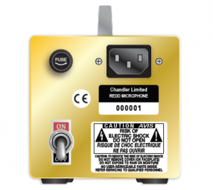
At the rear panel of the PSU, exists a standard male IEC connector for connection to AC power, using the supplied IEC cable. Also at the rear PSU panel is bayonet stylefuse compartment. For fuse replacement procedure and value, please reference the maintenance section of the manual.
POWER SWITCH
The master power switch is located at the bottom left of the PSU rear panel and labeled ON/OFF. Once all connections, to and from the microphone to the PSU havebeen made, flip the power switch to supply mains power to the microphone. NOTE: The microphone head basket will illuminate, signifying power is on.
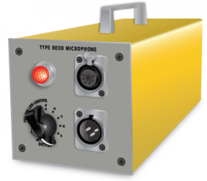
PSU FRONT PANEL

MIC INPUTThe top receptacle is a 7-pin female jack. Plug the supplied 25’ (762cm) 7-pin microphone cable here, and attach the female end of the cable to the microphone base connector.
LINE OUTPUTThe bottom receptacle is a standard 3-pin male XLR jack. This output jack supplies analog line level signal to your audiointerface converter, tape machine, orother external audio processor; the source(output) impedance is 200 ohms.
OUTPUT CONTROLThe ‘OUTPUT’ control is continuous, acting as a fader would on a console, and is used to reduce the overall output of the REDD Microphone; this control is functionally the same as the one found on the REDD.47 Mic Amplifier rack-mount unit. In most applications, attenuating the output of the microphone signal maybe unnecessary and should be left fully clockwise at unity or ‘0’. However, if reduction of the overall output signal is required, simply rotate the ‘OUTPUT’ control counterclockwise until the leveldesired level is achieved.
TIP- On drums room application, if a driven sound with tube saturation is the goal, turn up the gain, engage ‘DRIVE’ and turn down the ‘OUTPUT’ to not clip your converter’s input. The ‘OUTPUT’ control is operational regardless of the ‘PULL FOR LOW CONTOUR’ feature being actuated or not.
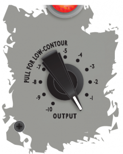
LOW-CONTOUR
The ‘LOW-CONTOUR’ function is an alternate voicing of the REDD Microphone, it features a tighter sound with top-emphasis and is an excellent choice for many sources.‘LOW-CONTOUR’ is available from the power supply (PSU,) to actuate the ‘LOW-CONTOUR’ voicing, simply pull the ‘OUTPUT’ control potentiometer outward; the ‘OUTPUT’ control is still fully operational. TIP- In recording scenarios and environments, where a more top-emphasized sound and a tailored low-end may bedesired, the ‘LOW-CONTOUR’ voicing is well suited for this purpose.
MAINTENANCE
STORAGE
When the REDD Microphone is not in use for extended periods of time, please stow the microphone system in the supplied pressure controlled waterproof case, in a room temperature environment.NOTE: If the microphone is to be left out for daily use, take care to use the provided plastic sheathe or suitable dust cover, to further protect capsule.
The dedicated on-board REDD.47 Mic Amplifier circuit relies on two vacuum tubes. Should one or both of the microphone tubes need replacement, please make the appropriate contact as found in the service section of this manual.
FUSE REPLACEMENT
WARNING- if, fuse replacement is necessary, make sure to replace using the same type of fuse only. FUSE TYPE: 1/2 AMP 250V SLO-BLO.If fuse replacement is required, make sure the PSU is disconnected from AC power by removing the power cord from the IEC receptacle, and or AC wall jack.Push gently on the fuse cap and turn in a counterclockwise motion, releasing the cap by unscrewing it until it is free from the fuse holder compartment.Place the new fuse (of the same type 1/2 AMP 250V SLO-BLO) into the fuse cap. While holding the fuse cap, insert the opposite end of the fuse into the fuse holder compartment and gently push the fuse cap inward, turning in a clockwise motion until the fuse cap is securely screwed into place; do not over-tighten.
U.S. SERVICE
Prior to sending in your gear for repair, please contact our shop at the number below. We will assist you in troubleshooting the problem and, if needed, we will issue you an RMA# to send in the gear.
Send repairs to:
Chandler Limited, Inc.Attention: Repairs222 S. Cherry St.PO Box 38 (if sending via the postal service)Shell Rock IA 50670Phone: (319) 885-4200Email:
INTERNATIONAL SERVICE
Repair of Chandler Limited products purchased outside of the United States, is provided by local or regional authorized Chandler Limited distributors. To obtain service or repairs, please contact your local dealer or regional distributor for further instruction.Visit chandlerlimited.com for a list of authorized International Distributors.
CE Certification
Chandler Limited declares under its sole responsibility that all products manufactured by them are in compliance with Electromagnetic Compatibility (EMC) Directive 2014/30/EU; Standards: EN55103-1:2009+A1:2012; EN55103-2:2009; EN55013:2013 and Low Voltage Directive (LVD) 2014/35/EU; Standards: EN60065:2002+A1:2006+A11:2008+A2:2010+A12:2011, EN60065:2014.
| REDD MICROHPONE SYSTEM | |||
| Item | Description | Dimensions | Weight |
| Microphone | Tube, Large Diaphragm Condenser | 10.97(L)x2.46(W) in (278.64×62.48 mm) | 1.11 lb / 0.504 kg |
|
Capsule |
Platinum membrane, custom handmade, hand- milled |
x |
x |
| Circuit | REDD.47 Mic Amplifier, Tube x2 | x | x |
| Gain | Switchable / +4 to
+33db in ‘NORM’ mode |
x | x |
| Maximum Gain | Extended gain in DRIVE mode | x | x |
| Patterns | Cardioid / Omni | x | x |
| PAD | 10db / Switchable | x | x |
| Phase | 0-180º / Switchable | x | x |
|
Power Supply |
External PSU, AC set internally for region, included | 11.4(L)x4.04(W) x4.81(H) in (289.56×102.62×122.17
mm) |
5.02 lb / 2.28 kg |
| Low-Contour Control | Preset, switchable | x | x |
| Output Control | Continuous, 200Ω out- put impedance | x | x |
| Fuse | 1 /2 AMP, 250V SLO-BLO | x | x |
| Accessories | |||
| Microphone Cable | 7 Pin, Mogami (Neglex 3172,) included | 25’ (7620 mm) | x |
| AC cable | Type IEC, included | 6’ (1828.8 mm) | x |
| Shockmount | Included | x | x |
| Pattern select screw- driver | Included | x | x |
|
Case |
Moulded flight case, included | 21.85(L)x8.31(W) x16.85(H) in (555x211x428 mm) |
20 lb / 9.07 kg, loaded |
Product Limited Warranty
During the first year from the date of the original purchase, this product is warranted to be free from defects in materials and workmanship under normal use, service and maintenance. This warranty applies to the original purchaser and is subject to the following terms and conditions:
What Is Covered: The product’s components as originally installed by the manufacturer that are defective in materials or workmanship under normal use, service and maintenance.
What Is Not Covered By This Warranty: This warranty does not extend to or cover:
- Any defect due to the negligence of others; failure to install, operate or maintain the product properly; unreasonable use; accidents; alteration; use of unauthorized or non-standardized parts; acts of God; theft; vandalism; electrical malfunctions (i.e., resulting from power surges, shorted or overloaded circuits, etc.), use of any power source other than supplied by manufacturer; repair by anyone other than an authorized Chandler Limited representative; or damage resulting from improper packing or mishandling by a shipper.
- Normal wear and tear of parts.
- Shipping, handling, packaging and delivery costs of the product.
Who Is Covered: The original purchaser.Repair During The First Year: During the first year, all defective product components that are covered by this Limited Warranty will be repaired free of charge including parts and labor. The purchaser will pay shipping costs AND a $35 handling fee per unit.What You Must Do for Warranty Service (in the United States): If you live in the United States and your product was purchased through a U.S. Dealer, please contact your dealer OR call 319-885-4200 or e-mail What You Must Do for Warranty Service (outside of the United States): For warranty service if you live outside of the United States, please contact the dealer where you purchased the product.
Any products returned to Chandler Limited for repair should include: (1) complete description of the problem; (2) name, address, phone number, fax number, and/or e-mail address; (3) receipt of original purchase; (4) power supply and all accessories and cables. The purchaser is responsible for the shipping costs to and from Chandler Limited. Chandler Limited is not responsible for damage resulting from improper packing and/or mishandling by a shipper.
If sent by UPS or Federal Express, ship to: Chandler Limited, 222 South Cherry Street, Shell Rock IA 50670If sent by Postal Service, ship to: Chandler Limited, PO Box 38, Shell Rock IA 50670The foregoing expresses Chandler Limited’s obligations and liabilities with respect to the quality of the product, its components and accessories. All other warranties, express or implied, including the warranties of merchantability or fitness for a particular purpose are disclaimed. Chandler Limited shall not be liable for the loss or use of the product, its components and accessories, inconvenience, loss or any other damages, direct or consequences arising out of the use of, or inability to use the product or its components or damages resulting from or attributable to defects in the products or its components. No one other than Chandler Limited has authority to extend or modify the terms of this limited warranty in any manner whatsoever.
DISCLAIMER OF WARRANTY
EXCEPT FOR THE FOREGOING WARRANTIES, CHANDLER LIMITED HEREBY DISCLAIMS AND EXCLUDES ALL OTHER WARRANTIES, EXPRESS OR IMPLIED, INCLUDING, BUT NOT LIMITED TO ANY AND/OR ALL IMPLIED WARRANTIES OF MERCHANTABILITY, FITNESS FOR A PARTICULAR PURPOSE AND/OR ANY WARRANTY WITH REGARD TO ANY CLAIM OF INFRINGEMENT THAT MAY BE PROVIDED IN SECTION 2-312(3) OF THE UNIFORM COMMERCIAL CODE AND/OR IN ANY OTHER COMPARABLE STATE STATUTE.
LIMITATION OF LIABILITY
THE LIABILITY OF CHANDLER LIMITED, IF ANY, AND PURCHASER’S SOLE AND EXCLUSIVE REMEDY FOR DAMAGES FOR ANY CLAIM OF ANY KIND WHATSOEVER, REGARDLESS OF THE LEGAL THEORY AND WHETHER ARISING IN TORT OR CONTRACT, SHALL NOT BE GREATER THAN THE ACTUAL PURCHASE PRICE OF THE PRODUCT WITH RESPECT TO WHICH SUCH CLAIM IS MADE. IN NO EVENT SHALL CHANDLER LIMITED BE LIABLE TO PURCHASER FOR ANY SPECIAL, INDIRECT, INCIDENTAL, OR CONSEQUENTIAL DAMAGES OF ANY KIND INCLUDING, BUT NOT LIMITED TO, COMPENSATION, REIMBURSEMENT OR DAMAGES ON ACCOUNT OF THE LOSS OF PRESENT OR PROSPECTIVE PROFITS OR FOR ANY OTHER REASON WHATSOEVER.
Read More About This Manual & Download PDF:
References
[xyz-ips snippet=”download-snippet”]