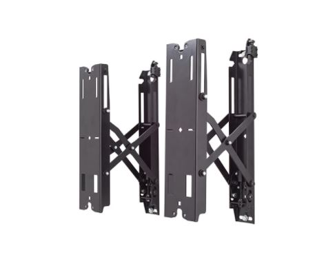
CHIEF Fusion Pull-Out Accessory
DISCLAIMERMilestone AV Technologies and its affiliated corporations and subsidiaries (collectively “Milestone”), intend to make this manual accurate and complete. However, Milestone makes no claim that the information contained herein covers all details, conditions, or variations, nor does it provide for every possible contingency in connection with the installation or use of this product. The information contained in this document is subject to change without notice or obligation of any kind. Milestone makes no representation or warranty, expressed or implied, regarding the information contained herein. Milestone assumes no responsibility for the accuracy, completeness, or sufficiency of the information contained in this document. Chief® is a registered trademark of Milestone AV Technologies. All rights reserved.
DEFINITIONSWARNING: A WARNING alerts you to the possibility of serious injury or death if you do not follow the instructions.
CAUTION: A CAUTION alerts you to the possibility ofdamage or destruction of equipment if you do not follow the corresponding instructions.
MOUNTING SYSTEM: A MOUNTING SYSTEM is the primary Chief product to which an accessory and/or component is attached.
ACCESSORY: AN ACCESSORY is the secondary Chief product that is attached to a primary Chief product, and may have a component attached or setting on it.
COMPONENT: A COMPONENT is an audiovisual item designed to be attached or resting on an accessory or mounting system such as a video camera, CPU, screen, display, projector, etc.
![]() IMPORTANT SAFETY INSTRUCTIONS
IMPORTANT SAFETY INSTRUCTIONS![]() WARNING: A WARNING alerts you to the possibility of serious injury or death if you do not follow the instructions.
WARNING: A WARNING alerts you to the possibility of serious injury or death if you do not follow the instructions.
![]() CAUTION: A CAUTION alerts you to the possibility of damage or destruction of equipment if you do not follow the corresponding instructions.
CAUTION: A CAUTION alerts you to the possibility of damage or destruction of equipment if you do not follow the corresponding instructions.
![]() WARNING: Failure to read, thoroughly understand, and follow all instructions can result in serious personal injury, damage to equipment, or voiding of factory warranty! It is the installer’s responsibility to make sure all products are properly assembled and installed using the instructions provided.
WARNING: Failure to read, thoroughly understand, and follow all instructions can result in serious personal injury, damage to equipment, or voiding of factory warranty! It is the installer’s responsibility to make sure all products are properly assembled and installed using the instructions provided.
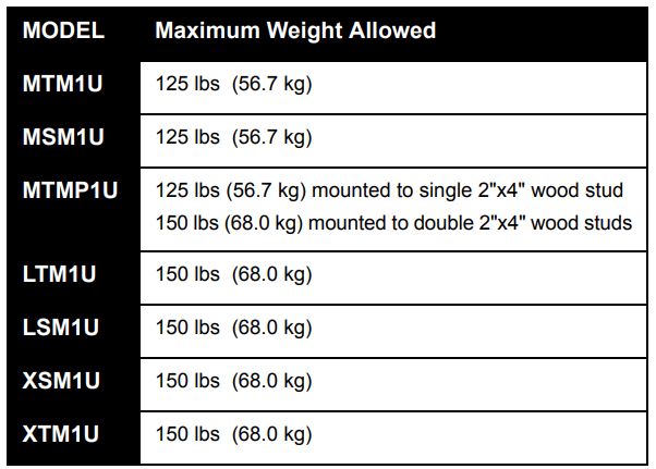
![]() WARNING: Exceeding the weight capacity can result in serious personal injury or damage to the equipment! Adding the FCAV1U accessory may change the weight capacity listed for the mounting system. Consult (Table 1) for mounting system’s weight capacity details when attached to FCAV1U.
WARNING: Exceeding the weight capacity can result in serious personal injury or damage to the equipment! Adding the FCAV1U accessory may change the weight capacity listed for the mounting system. Consult (Table 1) for mounting system’s weight capacity details when attached to FCAV1U.
Table 1: Weight Capacity When Attached to FCAV1U
![]() WARNING: Use this accessory only for its intended use as described in these instructions. Do not use attachments not recommended by the manufacturer.
WARNING: Use this accessory only for its intended use as described in these instructions. Do not use attachments not recommended by the manufacturer.
![]() WARNING: Never operate this accessory if it is damaged. Return the accessory to a service center for examination and repair.
WARNING: Never operate this accessory if it is damaged. Return the accessory to a service center for examination and repair.
![]() WARNING: Do not use this product outdoors.IMPORTANT !: The FCAV1U accessory is designed to be mounted to:
WARNING: Do not use this product outdoors.IMPORTANT !: The FCAV1U accessory is designed to be mounted to:
- a bare 8″ concrete or 8″x8″x16″ concrete block wall, or
- a 2″ x 4″ wood studs wall covered by drywall with a maximum thickness of 5/8″:
- MSM1U/MTM1U/MTMP1U: Wood studs must be 16″ on center;
- SM1U/LTM1U: Wood studs maybe 16″ or 24″ on center;
- SM1U/XTM1U: Wood studs may be 24″ or 32″ on center.
NOTE: Accessory is intended to be used with the following Chief mounting systems (not included):
- MTM1U
- MSM1U
- MTMP1U
- LTM1U
- LSM1U
- XTM1U
- XSM1U
–SAVE THESE INSTRUCTIONS–
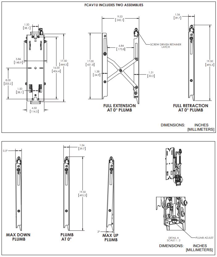
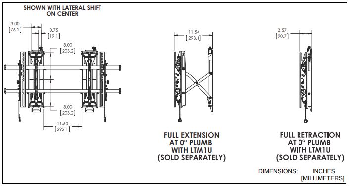
DIMENSIONS
LEGEND
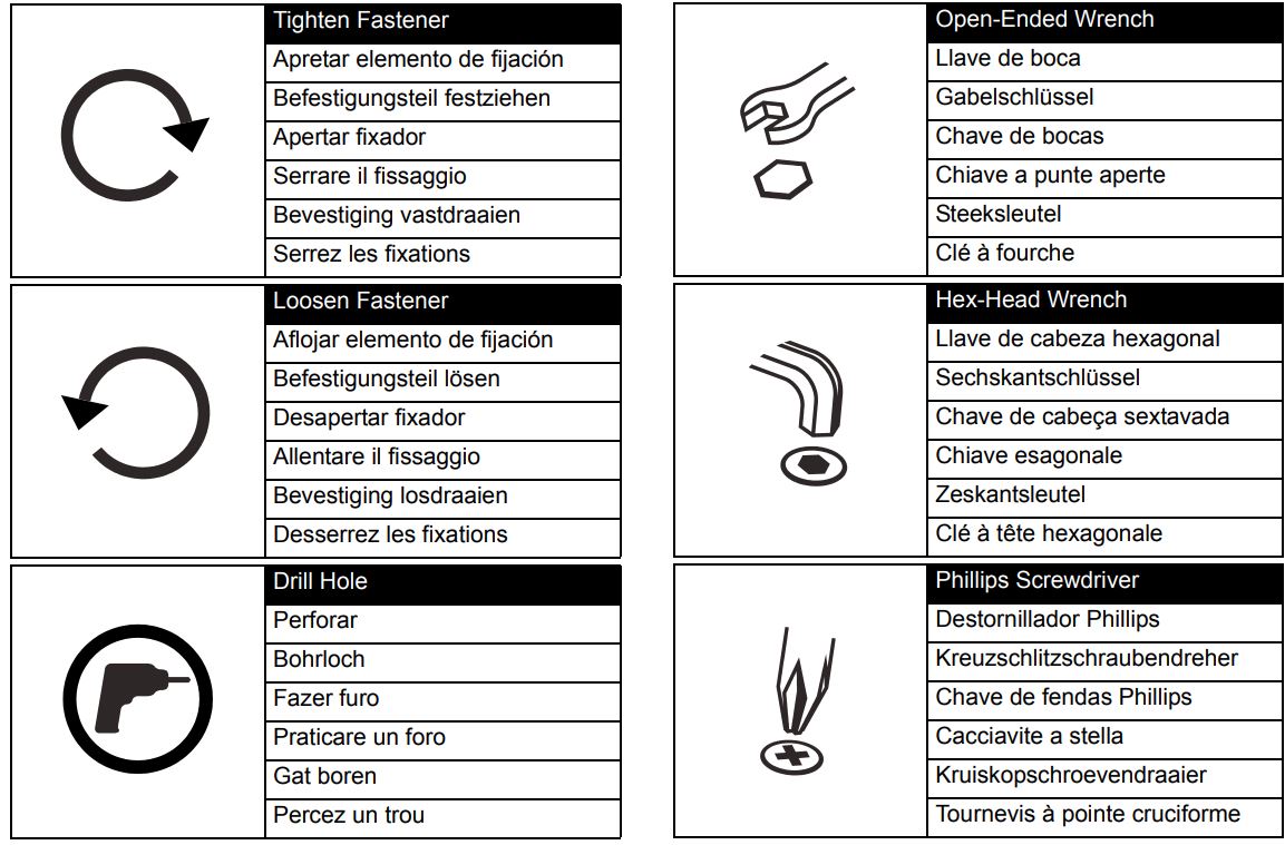
TOOLS REQUIRED FOR INSTALLATION

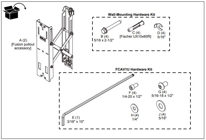
PARTS
INSTALLATION
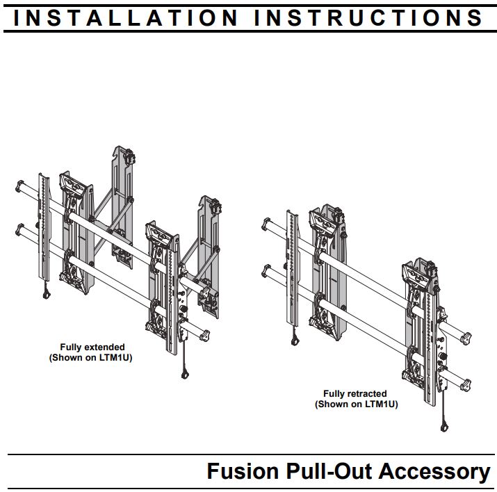
NOTE: The FCAV1U enables the mounting system to be pulled out away from the wall for any servicing needs.
Locate Mounting Site![]() WARNING: IMPROPER INSTALLATION CAN LEAD TO MOUNT FALLING CAUSING SEVERE PERSONAL INJURY OR DAMAGE TO EQUIPMENT! It is the responsibility of the installer to make certain the structure to which the accessory is being attached is capable of supporting five times the combined weight of accessory and mount, not to exceed weight capacities listed in Table 1 (See Table 1).NOTE: Proceed to either the Installing to a Wood Stud Wall section or the Installing to a Concrete Wall section.
WARNING: IMPROPER INSTALLATION CAN LEAD TO MOUNT FALLING CAUSING SEVERE PERSONAL INJURY OR DAMAGE TO EQUIPMENT! It is the responsibility of the installer to make certain the structure to which the accessory is being attached is capable of supporting five times the combined weight of accessory and mount, not to exceed weight capacities listed in Table 1 (See Table 1).NOTE: Proceed to either the Installing to a Wood Stud Wall section or the Installing to a Concrete Wall section.
Installing to a Wood Stud Wall
- Determine the center of the TV screen, and where it should be located on the wall.
- Locate the closest stud to the left and right of the selected location.NOTE: If the screen area lies over a stud, use that stud and the stud to either the left or right of it.
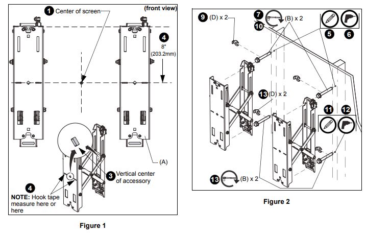
- Line up the diamond cutouts on Fusion pullout (A) with the center of screen marking to determine the vertical center. (See Figure 1)
- Measure up 8″ (203.2mm) from the center point (by hooking tape measure in slots on the front of FCAV1U) to mark the location of the upper mounting slots.
- Using a level, mark the wall on each stud to attach the accessory through the upper mounting slots. (See Figure 2)
- Drill one 7/32″ (5.5mm) pilot hole in each stud.NOTE: The slotted washers have been included to help make the installation easier. Wait to place the slotted washer AFTER the Fusion pullouts are hanging on the partially installed lag bolts. (See Steps 7-10)
- Partially install two 5/16 x 2-1/2″ flanged lag bolts (B) into pilot holes but do not tighten to the wall.
- Hang both Fusion pullouts (A), aligning upper mounting slots over lag bolts, and adjust side-to-side for proper location.
- Place one slotted washer (D) over each flanged lag bolt. (See Figure 2)
- Tighten lag bolts to secure accessory (A) to the wall at upper mounting slots.
- Mark the attachment points for the lower mounting slots, making sure the attachment points are located on the studs. (See Figure 2)
- Drill 7/32″ (5.5mm) pilot holes at markings for lower mounting holes. (See Figure 2)
- Use two 5/16 x 2-1/2″ flanged lag bolts (B) and two 5/16″ slotted washers (D) to attach both pullouts (A) to the wall through the lower mounting holes. (See Figure 2)
- Proceed to Attaching Mounting System section.
Installing to a Concrete Wall1. Determine the center of the TV screen, and where it should be located on the wall.2. Line up the notches on the accessory (A) with the center of screen marking to determine the vertical center. (See Figure 1)3. Measure up 8″ (203.2mm) from the center point to mark the location of the upper mounting slots. (See Figure 1)4. Using a level, mark the wall through both upper mounting slots. (See Figure 3)

![]() CAUTION: MINIMUM HORIZONTAL DISTANCE BETWEEN WALL BRACKETS IS 16″ (406.4mm). Do not place FCAV1U pullout accessories closer together than 16″ (406.4mm).5. Drill one 3/8″ x 3-1/2″ (9.5mm x 88.9mm) pilot hole at each marking.6. Install an anchor (C) into each pilot hole using a hammer, making sure that the anchor is flush with the wall.NOTE: The slotted washers have been included to help make the installation easier. Wait to place the slotted washer AFTER the Fusion pullouts are hanging on the partially installed lag bolts. (See Steps 7-10)7. Partially install two 5/16 x 2-1/2″ flanged lag bolts (B) into pilot holes but do not tighten to the wall.8. Hang accessory (A), aligning upper mounting slots over lag bolts, and adjust side-to-side for proper location.9. Place one slotted washer (D) over each flanged lag bolt. (See Figure 3)10. Tighten lag bolts to secure accessory (A) to the wall at upper mounting slots.11. Mark the attachment points for the lower mounting slots, making sure the attachment points are located on the studs. (See Figure 3)12. Drill 3/8″ x 3-1/2″ (9.5mm x 88.9mm) pilot holes at markings for lower mounting holes. (See Figure 3)13. Use two 5/16 x 2-1/2″ flanged lag bolts (B) and two 5/16″ slotted washers (D) to attach the accessory to the wall through the lower mounting holes. (See Figure 3)
CAUTION: MINIMUM HORIZONTAL DISTANCE BETWEEN WALL BRACKETS IS 16″ (406.4mm). Do not place FCAV1U pullout accessories closer together than 16″ (406.4mm).5. Drill one 3/8″ x 3-1/2″ (9.5mm x 88.9mm) pilot hole at each marking.6. Install an anchor (C) into each pilot hole using a hammer, making sure that the anchor is flush with the wall.NOTE: The slotted washers have been included to help make the installation easier. Wait to place the slotted washer AFTER the Fusion pullouts are hanging on the partially installed lag bolts. (See Steps 7-10)7. Partially install two 5/16 x 2-1/2″ flanged lag bolts (B) into pilot holes but do not tighten to the wall.8. Hang accessory (A), aligning upper mounting slots over lag bolts, and adjust side-to-side for proper location.9. Place one slotted washer (D) over each flanged lag bolt. (See Figure 3)10. Tighten lag bolts to secure accessory (A) to the wall at upper mounting slots.11. Mark the attachment points for the lower mounting slots, making sure the attachment points are located on the studs. (See Figure 3)12. Drill 3/8″ x 3-1/2″ (9.5mm x 88.9mm) pilot holes at markings for lower mounting holes. (See Figure 3)13. Use two 5/16 x 2-1/2″ flanged lag bolts (B) and two 5/16″ slotted washers (D) to attach the accessory to the wall through the lower mounting holes. (See Figure 3)
ATTACHING MOUNTING SYSTEM1. Attach the top of the mounting system (not included) to the top of FCAV1U accessories using two 5/16-18 x 1/2″ button head cap screws (G) and two 5/16″ washers (J) in each top mounting slot. (See Figure 4)2. Attach bottom of mounting system to bottom of FCAV1U accessories using two 1/4-20 x 1/2″ socket head cap screws (F) and two 1/4″ washers (H) in each bottom mounting slot. (See Figure 4)
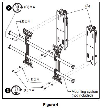
3. The remainder of the mounting system installation may be completed at this time, following the installation instructions included with the mounting system.
ADJUSTMENTS
Moving Mount to Wall (Optional)1. Close the FCAV1U brackets and tighten the retainer latch (turn counterclockwise) to hold the brackets in the retracted position. (See Figure 5)
IMPORTANT !: Do NOT over-tighten the retainer latch.
Moving Mount to Service Position2. Loosen the retainer latch by turning the screw clockwise. (See Figure 5)3. Pull the mount out from the wall.4. Return mount towards wall after service is complete.
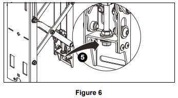
Adjusting Mount Against WallIMPORTANT !: Carefully adjust the mount plumb evenly on both sides to avoid placing too much stress on the screen.5. Adjust the plumb of the mount by turning the adjustment nut on the FCAV1U. (See Figure 6)
![]() Chief, a products division ofMilestone AV Technologies
Chief, a products division ofMilestone AV Technologies
8800-002781 Rev002016 Milestone AV Technologieswww.chiefmfg.com01/16
USA/International A 6436 City West Parkway, Eden Prairie, MN 55344P 800.582.6480 / 952.225.6000F 877.894.6918 / 952.894.6918
EuropeA Franklinstraat 14, 6003 DK Weert, NetherlandsP +31 (0) 495 580 852F +31 (0) 495 580 845
Asia PacificA Office No. 918 on 9/F, Shatin Galleria 18-24 Shan Mei Street Fotan, Shatin, Hong KongP 852 2145 4099F 852 2145 4477
References
[xyz-ips snippet=”download-snippet”]