Chief Medium Swing Arm MountsInstruction Manual
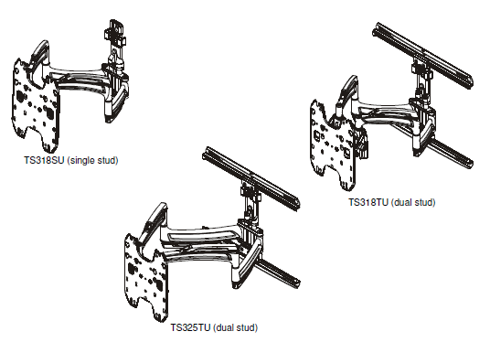
TS318SU/TS318TU/TS325TU
DISCLAIMER
Milestone AV Technologies and its affiliated corporations and subsidiaries (collectively “Milestone”), intend to make this manual accurate and complete. However, Milestone makes no claim that the information contained herein covers all details, conditions or variations, nor does it provide for every possible contingency in connection with the installation or use of this product. The information contained in this document is subject to change without notice or obligation of any kind. Milestone makes no representation of warranty, expressed or implied, regarding the information contained herein. Milestone assumes no responsibility for accuracy, completeness or sufficiency of the information contained in this document.
Chief® is a registered trademark of Milestone AV Technologies.All rights reserved.
IMPORTANT SAFETY INSTRUCTIONS
WARNING:
- A WARNING alerts you to the possibility of serious injury or death if you do not follow the instructions.CAUTION: A CAUTION alerts you to the possibility of damage or destruction of equipment if you do not follow the corresponding instructions.
- Failure to read, thoroughly understand, and follow all instructions can result in serious personal injury, damage to equipment, or voiding of factory warranty! It is the installer’s responsibility to make sure all components are properly assembled and installed using the instructions provided.
- Failure to provide adequate structural strength for this component can result in serious personal injury or damage to equipment! It is the installer’s responsibility to make sure the structure to which this component is attached can support five times the combined weight of all equipment.Reinforce the structure as required before installing the component.
- The wall to which the mount is being attached may have a maximum drywall thickness of 5/8″ (1.6cm) when installing any of the mounts to wood studs. If installing the TS318SU mount to poured concrete or hollow concrete, the wall CANNOT have ANY drywall covering! For the TS318TU and TS325TU, the wall CANNOT have ANY drywall covering if installing to poured concrete but may have a maximum drywall thickness of 5/8″ (1.6cm) if installing to hollow concrete block. Do not install drywall anchors into the seam between drywall pieces.
- Exceeding the weight capacity can result in serious personal injury or damage to equipment! It is the installer’s responsibility to make sure the combined weight of all components attached does not exceed 75 lbs (34 kg).
- Use this mounting system only for its intended use as described in these instructions. Do not use attachments not recommended by the manufacturer.
- Never operate this mounting system if it is damaged. Return the mounting system to a service center for examination and repair.
- Do not use this product outdoors.
–SAVE THESE INSTRUCTIONS–
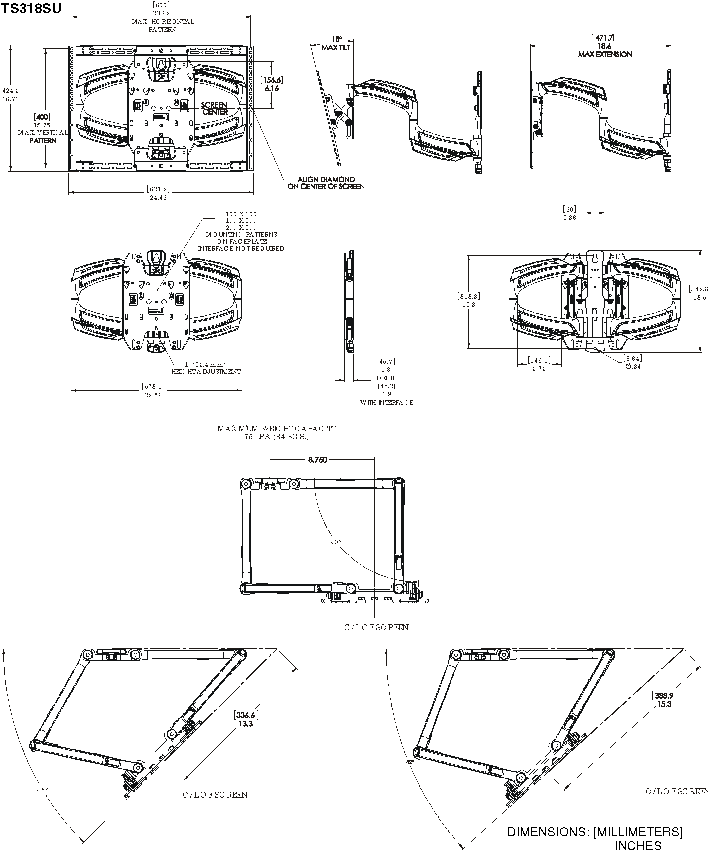
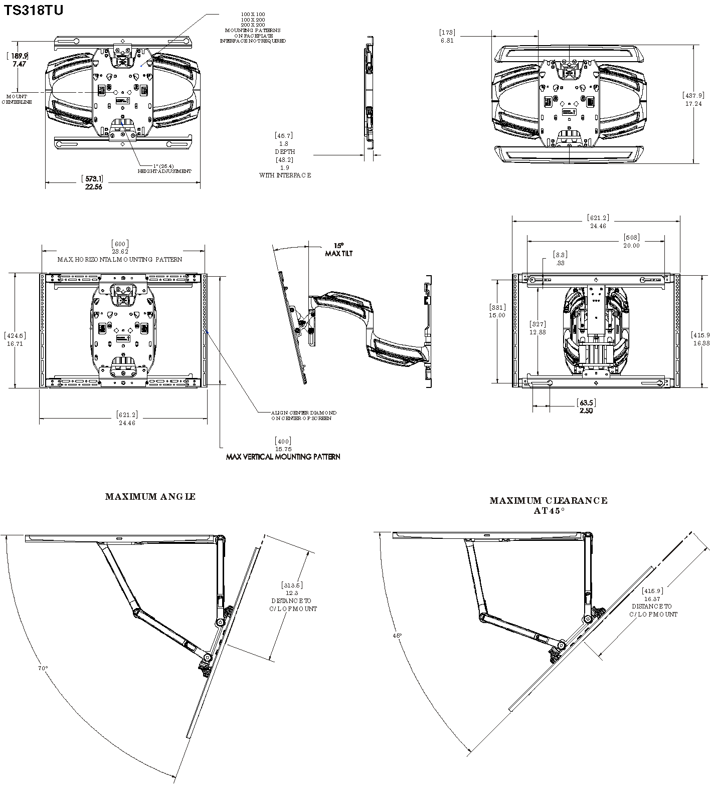
DIMENSIONS

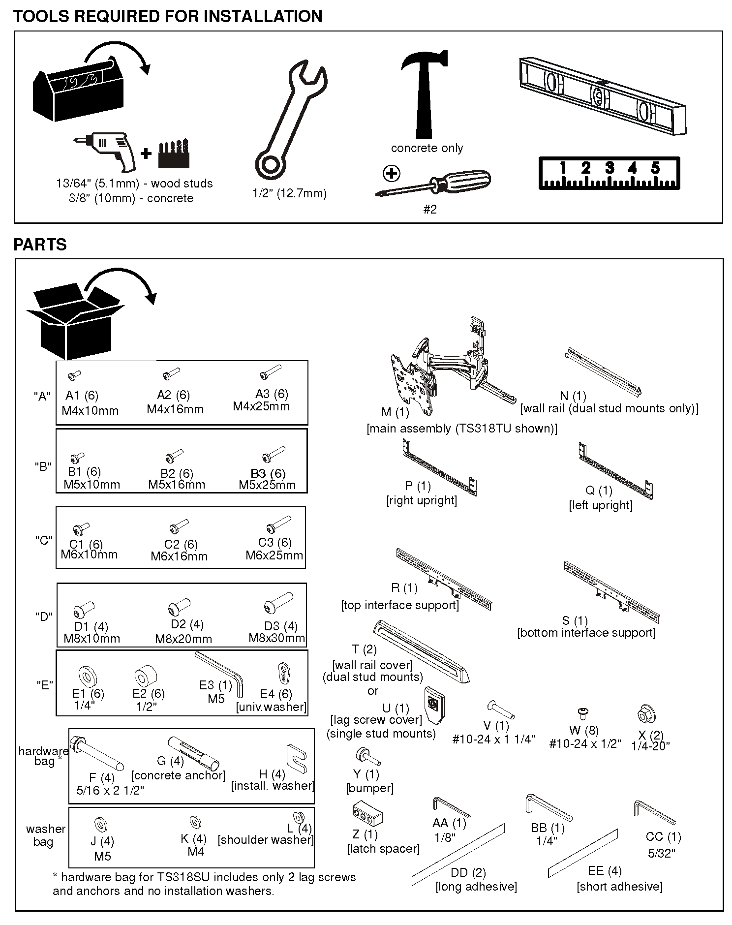
Assembly And Installation
Install TS318TU or TS325TU (Dual Stud) to WallNOTE: If installing TS318SU, proceed to Install TS318SU(Single Stud) to Wall section.
Install Wall Plate to Wall – Wood Studs
WARNING: Failure to provide adequate structural strength for this component can result in serious personal injury or damage to equipment! It is the installer’s responsibility to make sure the structure to which this component is attached can support five times the combined weight of all equipment.Reinforce the structure as required before installing the component. The wall to which the mount is being attached may have a maximum drywall thickness of 5/8″ (1.6cm).
- Determine mounting location.
- Measure 7 1/2″ above desired center line and draw a horizontal line. (See Figure 1)
NOTE: Hold mount up to wall at desired mounting location if unsure about where the center line will be. The center line of the mount will coincide with the center line of the display. (See Figure 1)
IMPORTANT ! : Use a level to make sure wall rail (N) is level when mounted to the wall!
3. Drill two 13/64″ holes at center of wood studs along the line drawn in the Step 2. Holes should be 2″ in depth. (See Figure 1)

4. Loosely attach wall rail (N) to wall using two 5/16- 2 1/2 flange head lag screws (F). (See Figure 2
5. Place two installation spacers (H) over two 5/16 x 2 1/2″ flange head lag screws (F). (See Figure 2)
6. Tighten two screws (F) to secure upper wall rail (N) to wall. (See Figure 2)

7. Slide main assembly (M) onto wall rail (N). (See Figure 3)

8. Center main assembly (M) over two studs.NOTE: Main assembly can be shifted laterally if desired. See Lateral Shift Adjustment section for details.
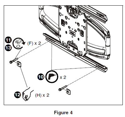
9. Drill two 13/64″ holes in center of wood studs at lower mounting holes. Holes should be 2″ in depth. (See Figure 4)
10. Loosely install two 5/16 x 2 1/2″ flange head lag screws (F). (See Figure 4)
11. Place two installation spacers over two flange head lag screws. (See Figure 4)
12. Tighten two screws to secure main assembly (M) to wall. (See Figure 4)
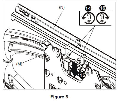
WARNING: DO NOT REMOVE SPACER AS SHOWN BELOW PRIOR TO INSTALLING THE LOWER TWO LAG SCREWS OR THE MOUNT WILL FALL OFF THE WALL WHEN THE SPACER IS REMOVED!
13. Loosen two flat head cap screws on upper carriage rail in order to loosen white spacer. (See Figure 5)
14. Remove white spacer from mount. (See Figure 5)
15. Tighten flat head cap screws. (See Figure 5)
Install Wall Plate to Wall – Hollow Concrete Block or Poured Concrete (Important!- Read warnings below for drywall restrictions!)
WARNING: Failure to provide adequate structural strength for this component can result in serious personal injury or damage to equipment! It is the installer’s responsibility to make sure the structure to which this component is attached can support five times the combined weight of all equipment. Reinforce the structure as required before installing the component.
WARNING: If installing to poured concrete, the wall CANNOT have ANY drywall covering! If installing to hollow concrete block, the wall to which the mount is being attached may have a maximum drywall thickness of 5/8″ (1.6cm). Do not install drywall anchors into the seam between drywall pieces.
1. Determine mounting location.
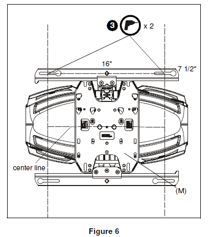
2. Measure 7 1/2″ above desired center line and draw a horizontal line. (See Figure 6)
NOTE: Hold mount up to wall at desired mounting location if unsure about where the center line will be. The center line of the mount will coincide with the center line of the display. (See Figure 6)IMPORTANT ! : Use a level to make sure wall rail (N) is level when mounted to the wall!
3. Drill two 3/8″ holes 16″ apart and along the line drawn in the Step 2. Holes should be 2 1/2″ in depth. (See Figure 6)
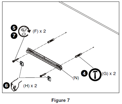
4. Install two concrete anchors (G) into two drilled holes. (See Figure 7)
5. Loosely attach wall rail (N) to wall by installing two 5/16 x 2-1/2″ flange head lag screws (F) into concrete anchors (G). (See Figure 7)IMPORTANT ! : Use a level to make sure wall rail (N) is level when mounted to the wall!
6. Place two installation spacers (H) over two 5/16 x 2 1/2″ flange head lag screws (F). (See Figure 7)
7. Tighten two screws to secure upper wall rail (N) to wall. (See Figure 7)
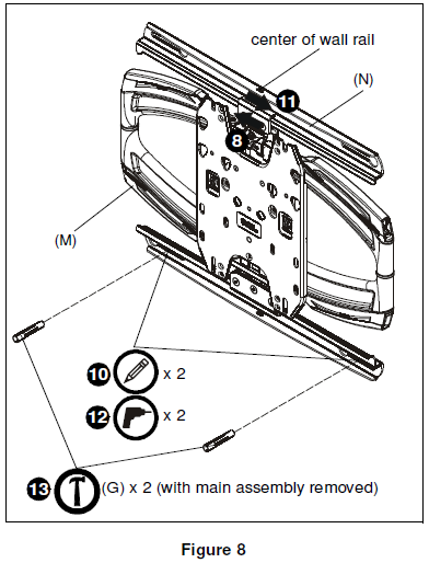
8. Slide main assembly (M) onto wall rail (N). (See Figure 8)NOTE: Main assembly can be shifted laterally if desired. See Lateral Shift Adjustment (Dual Stud Only) section for details.
9. Center main assembly (M) over wall rail (N). (See Figure 8)
10. Mark two holes at lower mounting holes. (See Figure 8)
11. Slide main assembly (M) off wall rail (N). (See Figure 8)
12. Drill two 3/8″ holes at marked locations. Holes should be 2 1/2″ in depth. (See Figure 8)
13. Install two concrete anchors (G) into drilled holes. (See Figure 8)
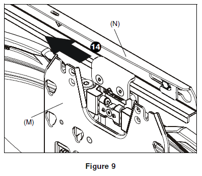
14. Slide main assembly (M) back onto wall rail (N). (See Figure 9)
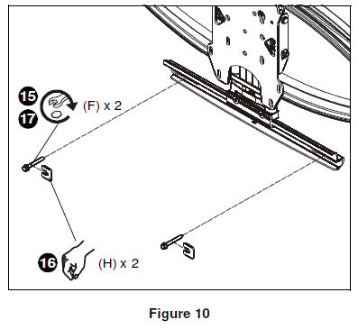
15. Loosely install two 5/16 x 2 1/2″ flange head lag screws (F) through lower wall rail on main assembly and into concrete anchors. (See Figure 10)
16. Place two installation spacers over two flange head lag screws. (See Figure 10)
17. Tighten two screws (F) to secure main assembly (M) to wall. (See Figure 10)
WARNING: DO NOT REMOVE SPACER AS SHOWN BELOW PRIOR TO INSTALLING THE LOWER TWO LAG SCREWS OR THE MOUNT WILL FALL OFF THE WALL WHEN THE SPACER IS REMOVED!
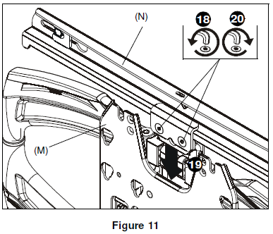
18. Loosen two flat head cap screws on upper carriage rail in order to loosen white spacer. (See Figure 11)
19. Remove white spacer from mount. (See Figure 11)
20. Tighten flat head cap screws. (See Figure 11)
21. Proceed ahead to Interface Installation section.
Install TS318SU (Single Stud) to Wall Install Wall Plate to Wall – Wood Studs
WARNING: Failure to provide adequate structural strength for this component can result in serious personal injury or damage to equipment! It is the installer’s responsibility to make sure the structure to which this component is attached can support five times the combined weight of all equipment. Reinforce the structure as required before installing the component. The wall to which the mount is being attached may have a maximum drywall thickness of 5/8″ (1.6cm).
- Determine mounting location.
- Measure 6 1/8″ above desired center line and mark a hole at desired mounting location on the center of wood stud. (See Figure 12)NOTE: Hold mount up to wall at desired mounting location if unsure about where the center line will be. The center line of the mount will coincide with the center line of the display. (See Figure 12)IMPORTANT ! : Use a level to make sure main assembly (M) is level when mounted to the wall!
- Drill one 13/64″ hole at location marked in Step 2. Hole should be 2″ in depth. (See Figure 12)

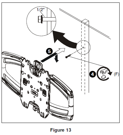
4. Install one 5/16- 2 1/2″ flange head lag screw (F) into hole, leaving screw hanging out 1/2″ from the wall. (See Figure 13)
5. Hang main assembly (M) onto lag screw (F) by latching keyshaped hole over top of screw. (See Figure 13)
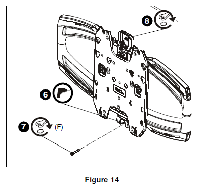
6. Mark and drill one 13/64″ hole at lower mounting hole location. Hole should be 2″ in depth. (See Figure 14)
7. Install 5/16-2 1/2″ hex flange lag screw (F) into lower mounting hole to secure main assembly to wall. (See Figure 14)
8. Tighten top lag screw to fully secure mount to wall. (See Figure 14)
9. Snap lag screw cover (U) onto wall mount over top lag screw. (See Figure 15)

10. Proceed ahead to Interface Installation section.
Install Wall Plate to Wall – Hollow Concrete Block or Poured Concrete (Important!- Read warnings below for drywall restrictions!)
WARNING: Failure to provide adequate structural strength for this component can result in serious personal injury or damage to equipment! It is the installer’s responsibility to make sure the structure to which this component is attached can support five times the combined weight of all equipment.Reinforce the structure as required before installing the component.
WARNING: If installing to poured concrete or hollow concrete block, the wall CANNOT have ANY drywall covering! Do not install drywall anchors into the seam between drywall pieces.
- Determine mounting location.
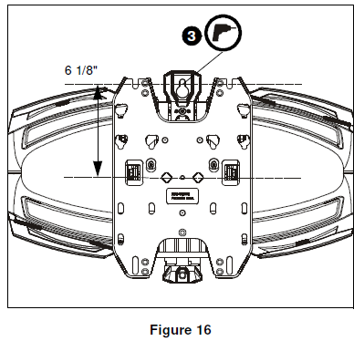
- Measure 6 1/8″ above desired center line and mark a hole at desired mounting location. (See Figure 16)
NOTE: Hold mount up to wall at desired mounting location if unsure about where the center line will be. The center line of the mount will coincide with the center line of the display. (See Figure 16)IMPORTANT ! : Use a level to make sure main assembly (M) is level when mounted to the wall!
3. Drill one 3/8″ hole at location marked in Step 2. Hole should be 2 1/2″ in depth. (See Figure 16)
4. Install one concrete anchor (G) into drilled hole. (See Figure 17)
5. Install one 5/16- 2 1/2″ flange head lag screw (F) into concrete anchor, leaving screw hanging out 1/2″ from the wall. (See Figure 17)
6. Hang main assembly (M) onto lag screw (F) by latching keyshaped hole over top of screw. (See Figure 17)

7. Mark and drill one 3/8″ hole at lower mounting hole location. Hole should be 2 1/2″ in depth. (See Figure 18)
8. Remove main assembly from wall. (See Figure 18)
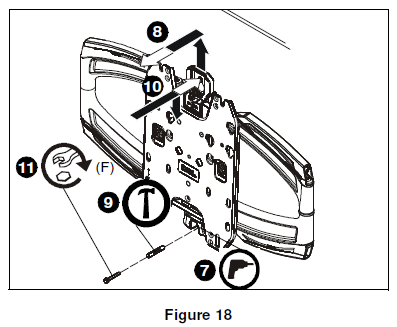
9. Install the other concrete anchor into drilled hole. (See Figure 18)
10. Place main assembly back onto wall. (See Figure 18)
11. Install 5/16-2 1/2″ hex flange lag screw (F) into concrete anchor to secure main assembly to wall. (See Figure 18)
12. Tighten top lag screw to fully secure mount to wall. (See Figure 18)
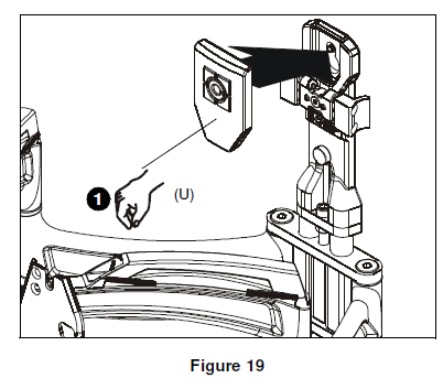
13. Snap lag screw cover (U) onto wall mount over top lag screw. (See Figure 19)
Interface Installation
IMPORTANT ! : If the display hole pattern size is 100mm x 100mm, 200mm x 200mm or 100mm x 200mm, the display can be mounted directly to the faceplate and the interface bracket DOES NOT need to be installed! Proceed to Installing Display without Interface Bracket section.
- Lay display face down on protective surface. CAUTION: Using screws of improper diameter may damage your display! Proper screws will easily thread into display mounting holes.
- Select screw diameter by examining hardware (A-D) (4mm, 5mm, 6mm or 8mm) and comparing with mounting holes on display. (See Figure 20)
- Select spacers: (See Figure 20)• If mounting holes are not recessed and both uprights (P and Q) can lay flat against display, then no spacers are required.• If mounting holes are recessed, or if protrusions prevent uprights (P and Q) from laying flat, then spacers (E1 or E2) must be used.CAUTION: Using screws of improper length may damage your display! Proper screws will have adequate thread engagement without contacting bottom of display mounting holes.
- Select screw length: (See Figure 20)• Using your hand, insert SHORTEST length screw of selected diameter (A1, B1,C1 or D1) through universal washer (E4), bracket (P or Q), selected spacer (E1 or E2, if required), into display mounting hole. Do NOT thread screw into hole at this time.NOTE: Universal washers (E4) are not needed if using M8 button head cap screws (D).• Proper screw length requires base of screw head to protrude above flat washer a distance equal to or greater than the screw diameter. If screw length is inadequate, select longer screw. Select shortest screw which will protrude the required distance.
- Place uprights (P and Q) on display, ensuring: (See Figure 21)• Center of uprights (P and Q) are as close to the center of the back of display as possible after being installed. Center of bracket is indicated by the diamond-shaped hole.NOTE: If installing to a display with a narrow hole mounting pattern, reverse uprights (P and Q) so that the upright legs do not overlap onto each other. (See Figure 21)
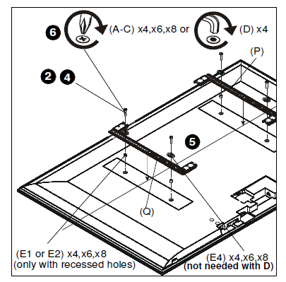

6. Using Phillips screwdriver, carefully install selected screws through universal washers (E4, if required), uprights (P and Q), and spacers (E1 or E2, if required), into display. (See Figure 20)
7. Tighten all screws. Ensure all applicable display mounting holes (4, 6, or 8) are used.
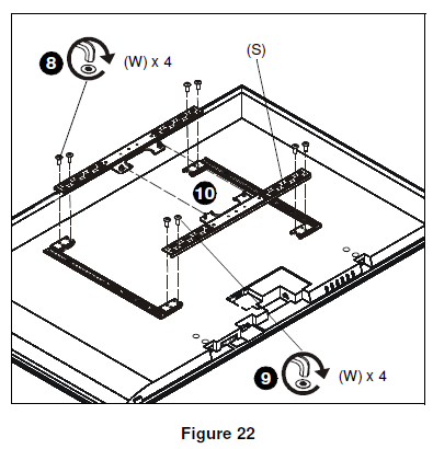
8. Connect top interface support (R) to uprights (P and Q) using four #10-24 x 1/2″ button head cap screws (W). (See Figure 22)
NOTE: If possible install screws diagonally across from each other in order to provide maximum support in Steps 8 and 9.
9. Connect bottom interface support (S) to uprights (P and Q) using four #10-24 x 1/2″ button head cap screws (W). (See Figure 22)
10. When connecting bottom interface support to uprights, make sure that it is aligned vertically with top interface support. (See Figure 22)
Install Display to Wall Plate
Using Interface Bracket
WARNING: Exceeding the weight capacity can result in serious personal injury or damage to equipment! It is the installer’s responsibility to make sure the combined weight of all components attached does not exceed 75 lbs (34 kg). Use with products heavier than the maximum weight indicated may result in collapse of the mount and its accessories causing possible injury.
WARNING: Display may be very heavy! Ensure display can be safely lifted and maneuvered as required to install on wall plate. Failure to take adequate precautions can result in serious personal injury or damage to equipment!
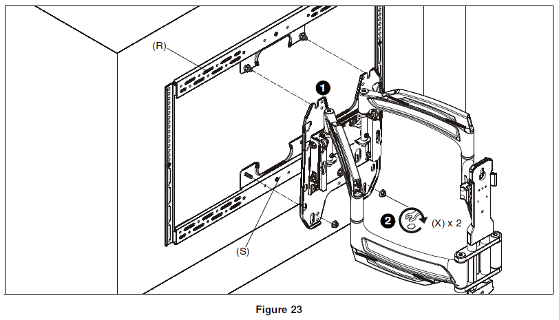
1. Hang interface bracket and display to faceplate by placing two mounting buttons on top interface support (R) over two teardrop grooves on top of faceplate. (See Figure 23)
2. Secure interface bracket and display to faceplate by installing two 1/4-20″ flange nuts (X) onto screws on lower interface support (S). (See Figure 23)
Installing Display Without Interface Bracket (100×100, 200×200 or 200×100)
CAUTION: Using screws of improper diameter may damage your display! Proper screws will easily thread into display mounting holes.
1. Select screw diameter by examining hardware (A-D) (4mm, 5mm, 6mm or 8mm) and comparing with mounting holes on display.CAUTION: Using screws of improper length may damage your display! Proper screws will have adequate threadengagement without contacting bottom of display mounting holes.
2. Select screw length:• Using your hand, insert SHORTEST length screw of selected diameter (A1, B1, C1 or D1) into display mounting hole. Do NOT thread screw into hole at this time.
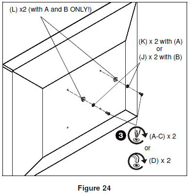
3. Install two selected screws (A-D) into upper two holes on back of display. (See Figure 24) IMPORTANT ! : If using M4 or M5 screws (A or B), washer hardware (J, K and L) must be used to ensure tight fit into the faceplate holes! For M4 screws (A), use M4 washer (K) and shoulder washer (L). For M5 screws (B), use M5 washer (J) and shoulder washer (L). (See Figure 24)
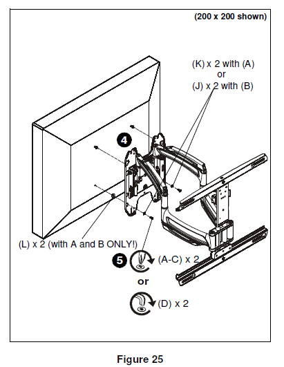
4. Hang display by two screws onto faceplate through either inner or outer teardrop mounting holes. (200×200 mounting pattern shown) (See Figure 25)
5. Install two selected screws (A-D) through selected washer hardware (H,J and K, if necessary), lower holes on faceplate and into lower two holes on display. (See Figure 25)
6. Tighten all hardware to ensure display is securely mounted.
Wall Cover Installation (Dual Stud)
1. Turn wall cover (T) outward to allow outside of covers to wrap around wall rail. (See Figure 26)
2. Place wall cover (T) over wall rail. (See Figure 26)

Cable Management
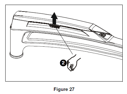
1. Make all cable connections to display.2. Open cable management covers on upper and lower swing arms by unhinging center tabs and lifting covers to the open position. (See Figure 27)
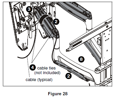
3. Route cables on top of upper arm. (See Figure 28)
4. (Optional) Use cable ties (not included) to secure cables to upper arms by threading ties around cable and through cable tie holes on arms. (See Figure 28)
5. Close upper cable management cover. (See Figure 28)
6. Route cables under lower portion of swing arm. (See Figure 28)
7. (Optional) Use cable ties (not included) to secure cables to lower arms by threading ties around cable and through cable tie holes on arms. (See Figure 28)
8. Close lower cable management cover. (See Figure 28)
Creating Space
In order to create more space between display and wall, spacers may be added.
- Extend swing arms in order to gain access to the center support.
- Remove flat hex-head screw holding latch to center support. (See Figure 29)
- Place latch spacer (Z) behind latch and line with holes on center support. (See Figure 29)
- Install #10-24 x 1 1/4″ flat hex-head screw (V) through latch and latch spacer and into holes on center support. (See Figure 29)

5. Remove 1/2″ knob assembly installed on center support. (See Figure 29)
6. Replace 1/2″ knob assembly with 1″ knob assembly (Y). (See Figure 29)
Height Adjustment
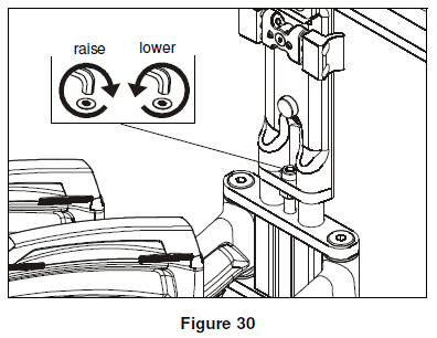
- Extend swing arms in order to gain access to the center support.
- Use 1/4″ hex key (BB) to adjust height adjustment screw to raise or lower mount to desired height. Turn clockwise to raise mount and counter-clockwise to lower mount. (See Figure 30)
Roll Adjustment
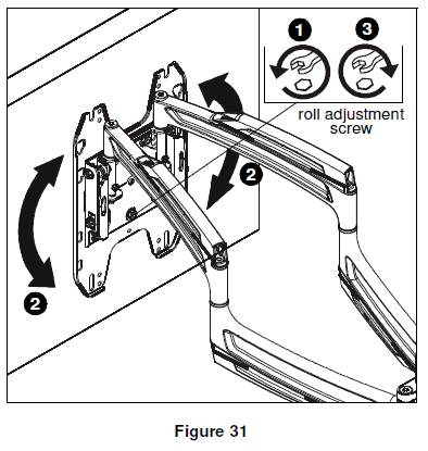
- Loosen roll tension adjustment screw on back of faceplate to decrease roll adjustment friction. (See Figure 31)
- Adjust roll position of display as desired. (See Figure 31)
- Tighten roll tension adjustment screw to desired friction level. (See Figure 31)
Tilt Friction Adjustment
- Tilt display forward enough to expose screws on the side of tilting mechanism. (See Figure 32)
- Adjust tilt friction adjustment screw to increase or decrease tilt friction. (See Figure 32)

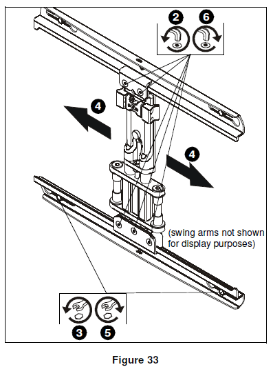
Lateral Shift Adjustment (Dual Stud only)
- Remove wall rail covers (N) to expose lateral shift adjustment screws on wall rails.
- Loosen five lateral shift adjustment screws using 3/16″ hex key (CC). (See Figure 33)
- Loosen two lower lag screws securing lower rail to the wall. (See Figure 33)
- Slide mount laterally to desired mounting position. (See Figure 33)NOTE: Removing the display from the mount will make adjusting the position of the mount much easier.
- Tighten two lower lag screws. (See Figure 33)
- Tighten five lateral shift adjustment screws. (See Figure 33)
- Reinstall wall rail covers (N).
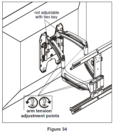
Arm Tension Adjustment
1. Use 1/4″ hex key (BB) to adjust arm tension at any of the four arm tension adjustment points. (See Figure 34)
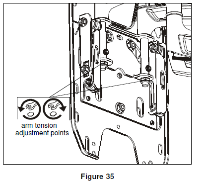
2. Use 9/16″ wrench to adjust arm tension directly behind faceplate. (See Figure 35)
Install Interface Bracket Adhesive Covers (Optional)
If the interface bracket was required to install display to mount, adhesive covers may be used to cover the holes on the interface bracket in order to improve the appearance.
1. Use two long adhesive strips (DD) to cover vertical uprights. (See Figure 36)2. Use four short adhesive strips (EE) to cover horizontal upright supports. (See Figure 36)
NOTE: These strips may be cut as desired in order to fit around screws.

Chief, a products division of Milestone AV Technologies8805-002014 Rev072014 Milestone AV Technologieswww.chiefmfg.com05/14
USA/International A 6436 City West Parkway, Eden Prairie, MN 55344P 800.582.6480 / 952.225.6000F 877.894.6918 / 952.894.6918Europe A Franklinstraat 14, 6003 DK Weert, NetherlandsP +31 (0) 495 580 852F +31 (0) 495 580 845Asia Pacific A Office No. 918 on 9/F, Shatin Galleria18-24 Shan Mei StreetFotan, Shatin, Hong KongP 852 2145 4099F 852 2145 4477
References
[xyz-ips snippet=”download-snippet”]