CHIEF PAC525 AV Component Adapter Bracket
DISCLAIMER
Milestone AV Technologies and its affiliated corporations and subsidiaries (collectively “Milestone”), intend to make this manual accurate and complete. However, Milestone makes no claim that the information contained herein covers all details, conditions or variations, nor does it provide for every possible contingency in connection with the installation or use of this product. The information contained in this document is subject to change without notice or obligation of any kind. Milestone makes no representation of warranty, expressed or implied, regarding the information contained herein. Milestone assumes no responsibility for accuracy, completeness or sufficiency of the information contained in this document.
Chief® is a registered trademark of Milestone AV Technologies. All rights reserved.
 IMPORTANT SAFETY INSTRUCTIONS
![]() WARNING: A WARNING alerts you to the possibility of serious injury or death if you do not follow the instructions.
WARNING: A WARNING alerts you to the possibility of serious injury or death if you do not follow the instructions.![]() CAUTION: A CAUTION alerts you to the possibility of damage or destruction of equipment if you do not follow the corresponding instructions.
CAUTION: A CAUTION alerts you to the possibility of damage or destruction of equipment if you do not follow the corresponding instructions.![]() WARNING: Failure to read, thoroughly understand, and follow all instructions can result in serious personal injury, damage to equipment, or voiding of factory warranty! It is the installer’s responsibility to make sure all components are properly assembled and installed using the instructions provided.
WARNING: Failure to read, thoroughly understand, and follow all instructions can result in serious personal injury, damage to equipment, or voiding of factory warranty! It is the installer’s responsibility to make sure all components are properly assembled and installed using the instructions provided.![]() WARNING: Failure to provide adequate structural strength for this accessory can result in serious personal injury or damage to equipment! It is the installer’s responsibility to make sure the structure to which this accessory is attached can support five times the combined weight of all equipment.
WARNING: Failure to provide adequate structural strength for this accessory can result in serious personal injury or damage to equipment! It is the installer’s responsibility to make sure the structure to which this accessory is attached can support five times the combined weight of all equipment.![]() WARNING: Exceeding the weight capacity can result in serious personal injury or damage to equipment! It is the installer’s responsibility to make sure the combined weight of all components located in the accessory does not exceed 10 lbs (4.5 kg).
WARNING: Exceeding the weight capacity can result in serious personal injury or damage to equipment! It is the installer’s responsibility to make sure the combined weight of all components located in the accessory does not exceed 10 lbs (4.5 kg).![]() WARNING: Use this mounting system only for its intended use as described in these instructions. Do not use attachments not recommended by the manufacturer.
WARNING: Use this mounting system only for its intended use as described in these instructions. Do not use attachments not recommended by the manufacturer.![]() WARNING: For indoor use only.
WARNING: For indoor use only.
IMPORTANT ! : The PAC525/526 mounts are designed to be mounted to a 2″ x 4″ wood stud wall 16″ on center, a 2″ x 4″ -25ga (minimum) steel studs wall, or to a 1/2″ minimum thickness drywall surface.
NOTE: Spacings – Minimum spacings between the 120 Vac power components and the A/V components shall be maintained for safe operation of the equipment when installed in accordance with the National Electric Code, ANSI/NFPA 70.
NOTE: When selecting a Listed 120 Vac Receptacle for use as the main power source for the PAC Series boxes (to power the A/V equipment), make sure that AC Receptacle is rated at least 15A and it is used in the building’s AC branch circuit that is connected to a circuit breaker rated at least 15A. Do not connect more than 12A from the Receptacle.In the U.S., the equipment shall be installed per the applicable requirements of the National Electrical Code, ANSI/NFPA 70.In Canada, the equipment shall be installed per the applicable requirements of the Canadian Electrical Code, CSA C22.1.
NOTE: It is the installer’s responsibility to ensure that the enclosure is bonded to the ground in the switch box, in accordance with the National Electric Code, ANSI/NFPA 70 or Canadian Electrical Code, CSA C22.1. A green grounding screw is provided in the enclosure for the purpose, if required.
–SAVE THESE INSTRUCTIONS–
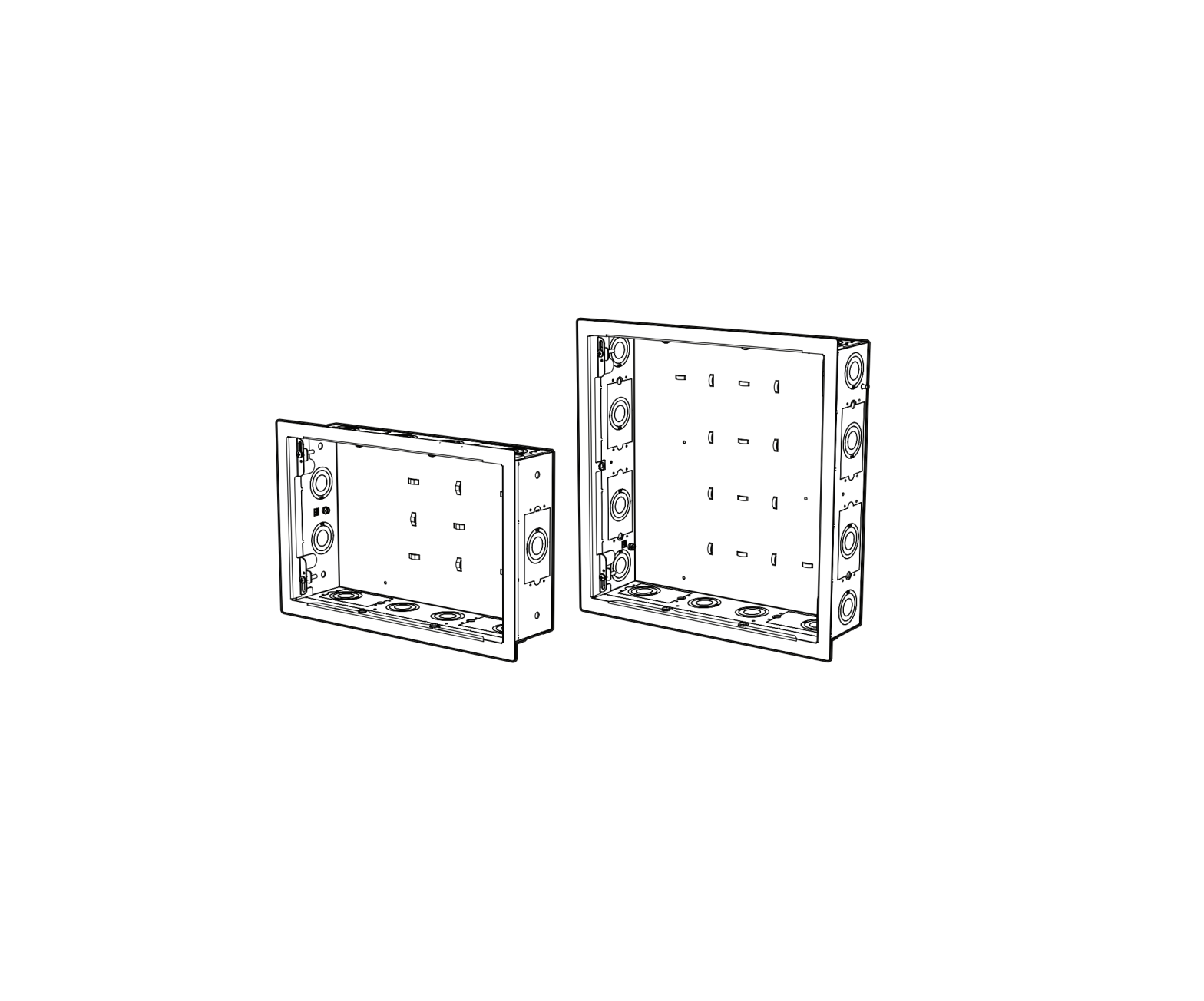
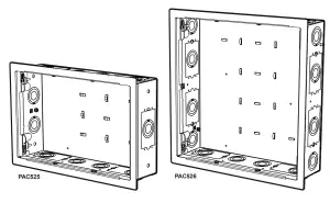
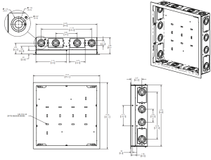
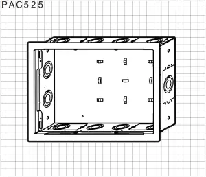
DIMENSIONS
PAC525

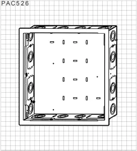
PAC526
LEGEND
 |
Tighten Fastener |  |
Pencil Mark |
 |
Loosen Fastener |  |
Drill Hole |
 |
Phillips Screwdriver |  |
Adjust |
 |
Flathead Screwdriver |  |
Remove |
 |
Mark level line |  |
Precision hand cut surface |
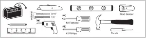
TOOLS REQUIRED FOR INSTALLATION
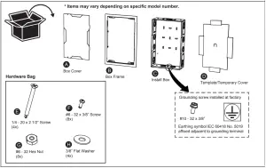
PARTS INCLUDED
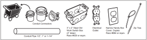
OPTIONAL PARTS PER CUSTOM CONFIGURATION (NOT INCLUDED)
INSTALLATION
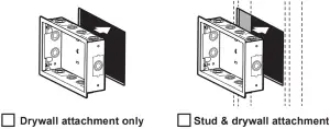
The PAC525/526 is intended for use both in installations where an existing finished drywall wall is present, and where the wall surface has not been finished and the structural studs are exposed. The wall then must be finished around the opening of the box after the box has been installed.
 |
PAC525/526 Project Planning
- Identify a suitable wall location for the accessory.
- Using a stud sensor, locate and mark studs.
- Identify possible structural conflicts (electrical wiring, plumbing, gaslines, HVAC).WARNING: ELECTRICAL SHOCK HAZARD! CUTTING OR DRILLING INTO ELECTRICAL WIRES OR CABLES CAN CAUSE DEATH OR SERIOUS PERSONAL INJURY! ALWAYS make certain area behind mounting surfaces is free of electrical wires and cables before cutting, drilling or installing fasteners.WARNING: EXPLOSION AND FIRE HAZARD! CUTTING OR DRILLING INTO GAS PLUMBING CAN CAUSE DEATH OR SERIOUS PERSONAL INJURY. ALWAYS make certain area behind mounting surfaces is free of gas, water, waste or any other plumbing before cutting, drilling or installing fasteners.
- Determine installation type. Housing is designed to fit between two adjacent wall studs, or onto a 1/2″ minimum thickness drywall surface.
- Plan box and component needs.Sketch diagrams provided.
- Determine all components needed.☐ Conduit Pipe☐ Conduit Connectors (large and small)☐ Electrical Box(es) (3” x 2”)☐ Steel Electrical Box Cover(s)☐ Zip Ties☐ Electrical Outlet(s)PAC525/526 Site Preparation
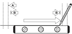
- Using a level, draw a horizontal line at lower edge of install site.A – STUD ATTACHMENT – create exploratory hole to confirm edge of stud/studs.B – DRYWALL ATTACHMENT – mark horizontal cut locations ensuring a minimum 1/2″ distance from each stud.
- Align on lower edge drawn line (A) and horizontal marking for inside stud location (B).Use enclosed template or housing as a template, drawing line around top and sides of housing.
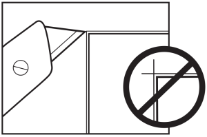
- Cut along outside edge of line using utility knife. Remove drywall.NOTE: Cutting past corners weakens the cleats’ ability to hold securely.
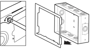
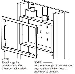
- Once wall opening is completed, check stud depth. If 3.5” or greater, proceed to step 11. If less than 3.5” deep, modify depth of box as follows before proceeding: CAUTION: Injury may occur on sharp edges. Carefully discard the removable tabs.A – Remove box flange by removing screws.B – Snap off removable tabs at perforations provided.CAUTION: Avoid sharp edges.C – Reinstall box flange. Reattach screws.PAC525/526 PAC525/526 Box Preparation
- Remove knock-outs in box as predetermined in step 5.
- Loosely attach components and conduit (cut to length) to box to ease fitting into wall opening.PAC525/526 Box Installation
- Feed attached conduit through cut-out and insert box into opening in wall. Tighten component connections.
- Secure box into place by methods chosen.DRYWALL ATTACHMENT: Slide locking cleats into place. Tighten screws to secure.STUD ATTACHMENT:Drill pilot holes (optional) into studs through mounting holes in box. Wood studs – use 3/16” bit. If steel studs – use 1/4” bit. Install with 1/4 – 20 x 2 1/2” screws (E) and 3/8” flat washers (H) into pilot holes.
- NOTE:Box may be installed with outer flange removed for a pre-sheetrock open stud mount configuration.PAC525/526 Final Finishing
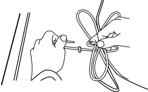
- Using preferred attachment method (zip ties, bands, etc. – none included), secure AV components and cables within the wall box. Attachment methods may use integrated attachment points at back of wall box or other appropriate points.
- Install template as temporary cover if needed to protect from debris by folding tabs in and inserting into opening.
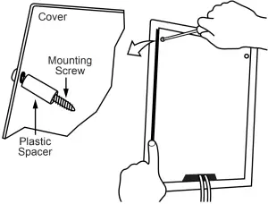
- Modify enclosure cover before attaching. Break away tab(s) to allow wire exit from box and meet ventilation needs.
- Gather wires and route through cover opening. Install cover, screw fasteners(2) into place to secure and complete enclosure.


 B – Snap off removable tabs at perforations provided.
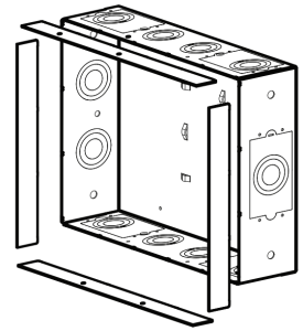 C – Reinstall box flange. Reattach screws.
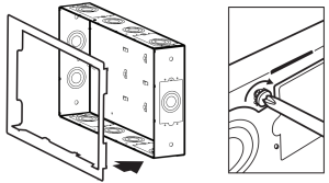
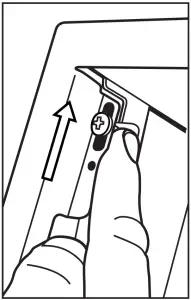 STUD ATTACHMENT:Drill pilot holes (optional) into studs through mounting holes in box. Wood studs – use 3/16” bit. If steel studs – use 1/4” bit. Install with 1/4 – 20 x 2 1/2” screws (E) and 3/8” flat washers (H) into pilot holes.
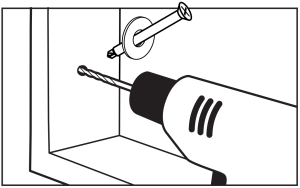


Chief, a products division of Milestone AV Technologies
8800-002517 Rev02 2015 Milestone AV Technologieswww.chiefmfg.com
| USA/International | A 6436 City West Parkway, Eden Prairie, MN 55344P 800.582.6480 / 952.225.6000F 877.894.6918 / 952.894.6918 |
| Europe | A Franklinstraat 14, 6003 DK Weert, NetherlandsP +31 (0) 495 580 852F +31 (0) 495 580 845 |
| Asia Pacific | A Office No. 918 on 9/F, Shatin Galleria 18-24 Shan Mei Street Fotan, Shatin, Hong KongP 852 2145 4099F 852 2145 4477 |
 report this ad
References
[xyz-ips snippet=”download-snippet”]