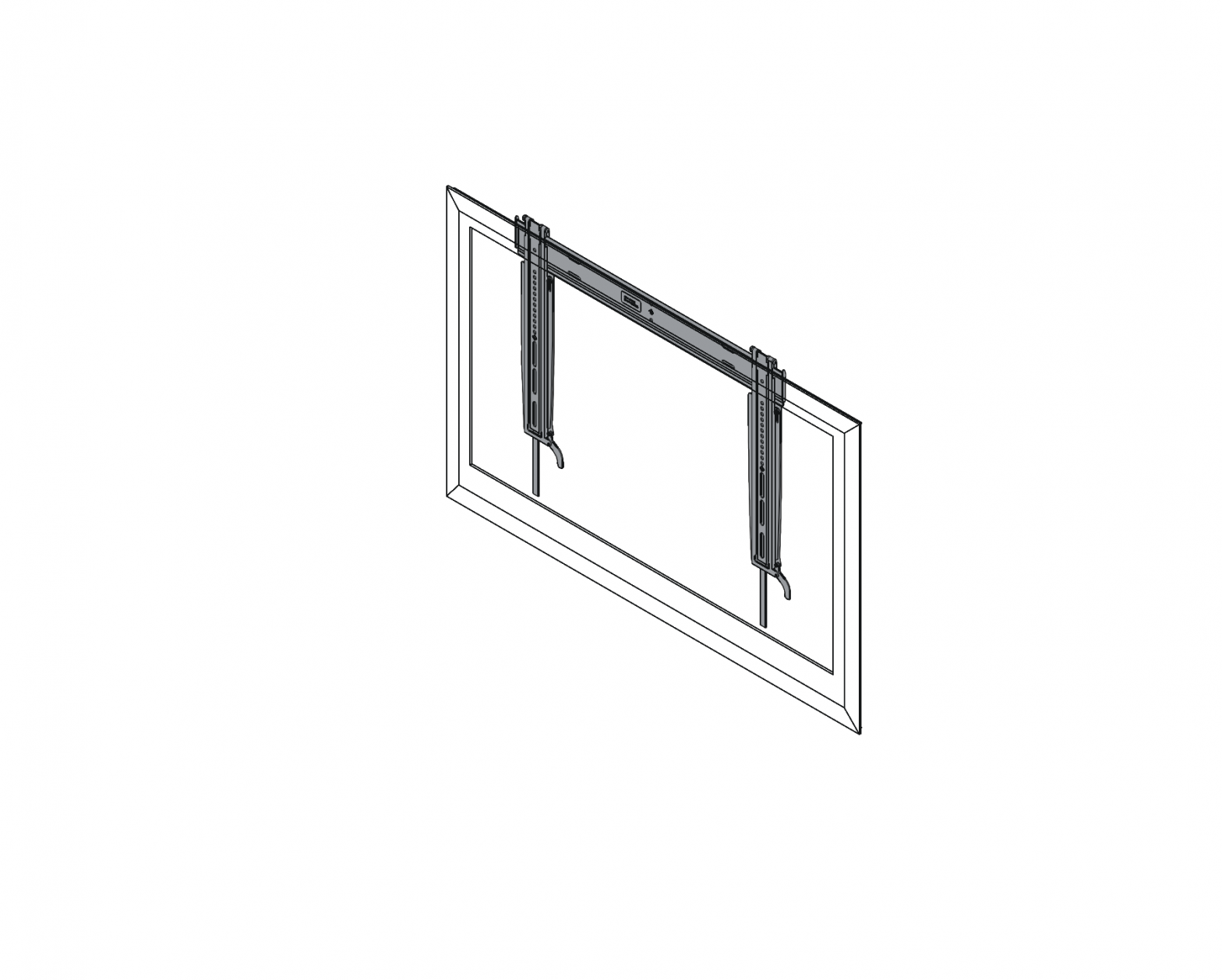
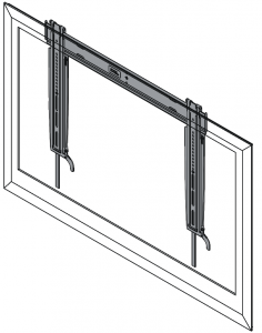
CHIEF Thinstall Medium Static Universal Mount
DISCLAIMER
Milestone AV Technologies, and its affiliated corporations and subsidiaries (collectively, “Milestone”), intend to make this manual accurate and complete. However, Milestone makes no claim that the information contained herein covers all details, conditions or variations, nor does it provide for every possible contingency in connection with the installation or use of this product. The information contained in this document is subject to change without notice or obligation of any kind. Milestone makes no representation of warranty, expressed or implied, regarding the information contained herein. Milestone assumes no responsibility for accuracy, completeness or sufficiency of the information contained in this document.
Chief® and Thinstall™ are registered trademarks of Milestone AV Technologies. All rights reserved.
 MPORTANT SAFETY INSTRUCTIONS!
 MPORTANT SAFETY INSTRUCTIONS!
![]() WARNING: A WARNING alerts you to the possibility of serious injury or death if you do not follow the instructions.
WARNING: A WARNING alerts you to the possibility of serious injury or death if you do not follow the instructions.![]() CAUTION: A CAUTION alerts you to the possibility of damage or destruction of equipment if you do not follow the corresponding instructions.
CAUTION: A CAUTION alerts you to the possibility of damage or destruction of equipment if you do not follow the corresponding instructions.![]() WARNING: Failure to read, thoroughly understand, and follow all instructions can result in serious personal injury, damage to equipment, or voiding of factory warranty! It is the installer’s responsibility to make sure all components are properly assembled and installed using the instructions provided.
WARNING: Failure to read, thoroughly understand, and follow all instructions can result in serious personal injury, damage to equipment, or voiding of factory warranty! It is the installer’s responsibility to make sure all components are properly assembled and installed using the instructions provided.![]() WARNING: Failure to provide adequate structural strength for this component can result in serious personal injury or damage to equipment! It is the installer’s responsibility to make sure the structure to which this component is attached can support five times the combined weight of all equipment. Reinforce the structure as required before installing the component.
WARNING: Failure to provide adequate structural strength for this component can result in serious personal injury or damage to equipment! It is the installer’s responsibility to make sure the structure to which this component is attached can support five times the combined weight of all equipment. Reinforce the structure as required before installing the component.![]() WARNING: Exceeding the weight capacity can result in serious personal injury or damage to equipment! It is the installer’s responsibility to make sure the combined weight of all components located between the MSTU up to (and including) the display does not exceed 125 lbs (56.7 kg).
WARNING: Exceeding the weight capacity can result in serious personal injury or damage to equipment! It is the installer’s responsibility to make sure the combined weight of all components located between the MSTU up to (and including) the display does not exceed 125 lbs (56.7 kg).
- The weight capacity of the MSTU may be LIMITED to the lowest weight capacity of any other component or accessory used within the mounting system
![]() WARNING: Use this mounting system only for its intended use as described in these instructions. Do not use attachments not recommended by the manufacturer.
WARNING: Use this mounting system only for its intended use as described in these instructions. Do not use attachments not recommended by the manufacturer.![]() WARNING: The depth of the display cannot exceed 5 inches (127 mm).
WARNING: The depth of the display cannot exceed 5 inches (127 mm).![]() WARNING: The MSTU fits all hole patterns between 100 x 100mm and 600 x 400mm.
WARNING: The MSTU fits all hole patterns between 100 x 100mm and 600 x 400mm.![]() WARNING: Never operate this mounting system if it is damaged. Return the mounting system to a service center for examination and repair.
WARNING: Never operate this mounting system if it is damaged. Return the mounting system to a service center for examination and repair.![]() WARNING: Do not use this product outdoors.
WARNING: Do not use this product outdoors.
IMPORTANT ! : The MSTU mount is designed to be mounted:
- 2″ x 4″ wood studs that are 16″ on center, or
- a concrete wall with a minimum thickness of 8″, or
- a bare 8″ x 8″ x 16″ concrete block wall.
–SAVE THESE INSTRUCTIONS–
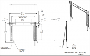
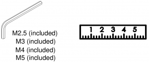
DIMENSIONS
LEGEND
 |
Tighten Fastener |

|
Measure |
 |
Phillips Screwdriver |
 |
By Hand |
 |
Hex-Head Wrench |

|
Hammer |
 |
Pencil Mark |
 |
Drill Hole |
 |
Adjust |
 |
Optional |
 |
Security Wrench |

|
Open-Ended Wrench |
TOOLS REQUIRED FOR INSTALLATION
 TOOLS REQUIRED FOR INSTALLATION
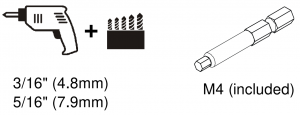
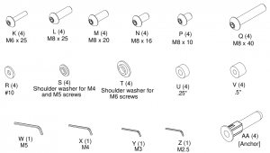
PARTS
 PARTS
PARTS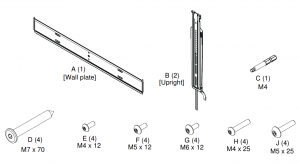
Assembly And Installation
Wall Plate Installation Using Wood Studs
- Determine location for mount keeping in mind display size and safety requirements.
- Use stud finder to locate studs. Wall plate can be mounted on 2″ x 4″ wood studs that are 16″ apart.
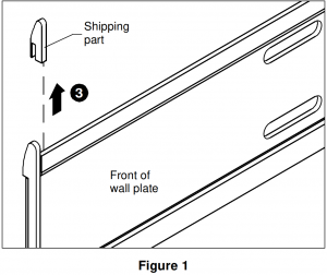
- Remove and discard two plastic shipping parts from the wall plate (one from each end). (See Figure 1)
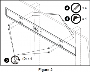
- Using wall plate as template, mark and then drill four 3/16″ diameter pilot holes, making sure the holes are centered in the middle of each stud. The holes must be drilled at least 2-1/4″ deep. (See Figure 2)
- Install four connector screws (D) through wall plate and into pilot holes using M4 Allen Head bit (C). (See Figure 2)
Wall Plate Installation into Concrete or Concrete Block
- Determine location for mount keeping in mind display size and safety requirements.
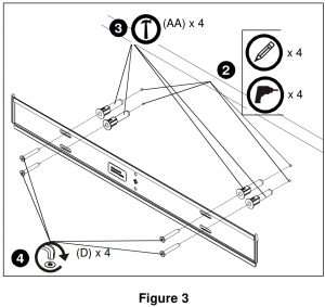
- Using wall plate as a template, mark and then drill four 5/16″ diameter pilot holes through mounting surface. Use level to make sure wall plate is perfectly horizontal. Holes must be drilled at least 2-1/4″ deep. (See Figure 3)
- Install four anchors (AA) into pilot holes drilled in Step 2. Use a hammer to tap anchors into holes. (See Figure 3)
- Install four connector screws (D) through wall plate holes and into anchors. (See Figure 3)
Display Installation
- Lay display face side down on a level, non-abrasive surface. Lay down a cloth if necessary to avoid scratching the screen.
- Position two interface brackets (B) over holes in back of display to determine which holes will be used for installation.NOTE: Interface brackets should be positioned so that the diamond hole in the bracket is located halfway between the installation holes in order to ensure proper weight distribution.NOTE: Spacers may not be required depending on the type of display being mounted. They will typically only be used with recessed or bump-out back screens.NOTE: Cable management pull straps should be easily accessible underneath the display. Length of straps can be adjusted if necessary.
- Determine which screws to use to connect interface brackets to display. Use the screws that fit into the holes on the back of the display. Make sure screws can make at least three full turns into mounting holes. If not, select longer screw from hardware kit.
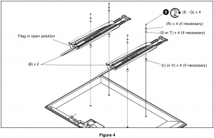
- Determine which washers and shoulder washers to use with the corresponding screw. Refer to table below for details.
Screw Size Washers Shoulder Washers M4 use R use S M5 use R use S M6 none use T M8 none none - Install four button head cap screws (E – Q) through required washers (R) and shoulder washers (S or T), interface brackets (B), spacers (U or V) and into holes on back of display. (See Figure 4) WARNING: IMPROPER INSTALLATION CAN LEAD TO MOUNT FALLING CAUSING SEVERE PERSONAL INJURY OR DAMAGE TO EQUIPMENT. Displays can weigh in excess of 40 lbs (18.1 kg). ALWAYS use two people and proper lifting techniques when installing display. WARNING: Exceeding the weight capacity can result in serious personal injury or damage to equipment! It is the installer’s responsibility to make sure the combined weight of all components located between the MSTU up to (and including) the display does not exceed 125 lbs (56.7 kg).NOTE: Make sure locking flags are in the open position before attaching display to wall plate. Flags are shown in the open position in Figure 4.NOTE: Display can be adjusted horizontally as long as guide hooks are securely attached to wall plate.IMPORTANT ! : If spacers are required, be sure to use screws that are longer than the spacers but of the same diameter!
- While supporting both sides of display, lift display up to the wall plate on the wall.
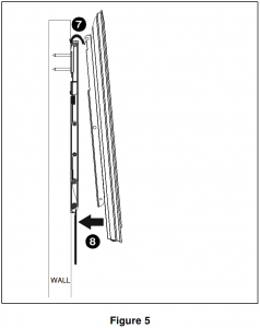
- Slowly guide hooks on top of interface brackets on top of wall plate in desired mounting location. (See Figure 5)
- Slowly swing display toward wall. (See Figure 5)
- Slowly pull bottom of display away from wall until kickstand fully reaches its down position. (See Figure 6)
- Slowly release display until kickstand locks against bottom of mount.
- Rotate flags on each interface bracket to the closed position in order to lock brackets to wall plate. (See Figure 6)
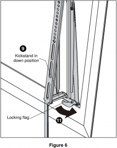
NOTE: Flags should stay in locked position unless removing display from wall bracket.
Cable Management
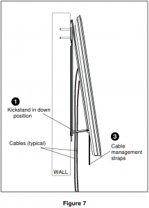
NOTE: For attaching and adjusting cables, the MSTU mount features a kickstand to allow access without having to remove display from the wall.
- Ensure kickstand is firmly in down position.
- Attach or adjust cables as necessary on back of display.
- To disengage kickstand, slightly pull display away from wall and pull down on cable management straps to release kickstand. Slowly allow display to return to the wall. (See Figure 7)
NOTE: Due to the low-profile design of the Thinstall Series, displays with cable connections coming straight out of the back may require 90-degree cable connectors. Chief offers in-wall accessories that can assist with recessing cables and connections.NOTE: Certain displays may have limited space available for cable management.
 Chief, a products division of Milestone AV Technologies
8800-002508 Rev00¤2014 Milestone AV Technologieswww.chiefmfg.com
References
[xyz-ips snippet=”download-snippet”]