
Installation GuideChroma-Q ® Inspire™Blind Sloped Ceiling Mount
For Use With:
CHINSIK15B, CHINSIK15W, CHINSIK30B, CHINSIK30W (Model: 632-9300, 632-9301, 632-9305, 632-9306)
Inspire Sloped Ceiling Blind Mount Install Guide V1.2 Model: 632-0990
Installation Disclaimer:
- Installation should be carried out by an experienced professional. The instructions below are provided for information only.
- All work should be verified to meet Local and National Building Regulations, and Health and Safety Standards in particular.
- Ensure that the specified torque is applied to fasten the Trim Ring and Angle Supports.
- The Angle Supports of the Inspire fixture must be fastened to the ceiling with the appropriate load capacity.
- The use of a safety-rated chain or other arrest cable is strongly recommended as per standard rigging practice.
- KIT CONTENTS
Items
Part Number QTY
Trim Ring Inspire 632-0055 or 632-0057 (0-15°)632-0056 or 632-0058 (20-30°) 1 Cross Brace 632-0060 2 Bracket Hook 632-0050 2 Angle support ceiling mounting 632-0041 2 Corner Hook LH 632-0065 1 Corner Hook RH 632-0066 1 Bracket attachment LH 632-0070 1 Bracket attachment RH 632-0071 1 Spring Plunger 3/8’’ – 16 338-5225-2 1 Binding Post 5/16’’ 331-5675-2 2 Screw M3 x 6 PH PLPS SS A2 430-1506-2 12 Screw M5 x 20 FHSCS ST 450-1120-5 4 - Tools RequiredScrewdriver with PH#1 for the M3 screw (Minimum torque: 5.5 in-lb.)Screwdriver with Hex 5/32” for the ¼-20” flanged button head socket screw (Minimum torque: 48 in-lb.)
- Installation Guide
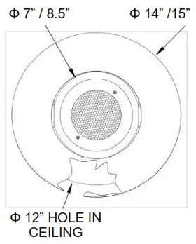
 Hole Sizing Reference (inches/cm)Note:– Ceiling hole size: 12” / 30.5 cm– For 0-15° (632-0055 / 632-0057) Trim Ring outer diameter: 14” / 35.5 cm Trim Ring inner diameter: 7.5” / 19 cm– For 20-30° (632-0056 / 632-0058) Trim Ring outer diameter: 15” / 38 cm Trim Ring inner oval cut-out: major axis Length 8.5” / 21.5 cmminor axis Length 7” / 18 cm
 Hole Sizing Reference (inches/cm)Note:– Ceiling hole size: 12” / 30.5 cm– For 0-15° (632-0055 / 632-0057) Trim Ring outer diameter: 14” / 35.5 cm Trim Ring inner diameter: 7.5” / 19 cm– For 20-30° (632-0056 / 632-0058) Trim Ring outer diameter: 15” / 38 cm Trim Ring inner oval cut-out: major axis Length 8.5” / 21.5 cmminor axis Length 7” / 18 cm
- Install Bracket Hooks:1. Remove the faceplate of the fixture by taking out 2 x M3 FH screws.2. Insert the two Bracket hooks on opposite ends.3. Put back the face plate on the fixture installing the screws back on it.
- Install Brackets & Binding Posts:1. Install the bracket attachments (LH/RH) using M5 x 20 screws and Binding Posts into threaded holes of bracket hooks.2. Tighten the screws to make a solid connection to the fixture.
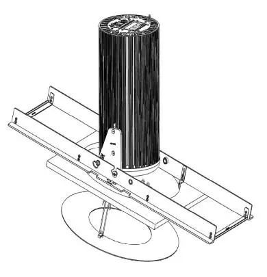
- Assemble Angle Support Assembly:1. Install 2 x Cross brace and 2 x Corner hooks using M3 x 6 screws using the hardware provided, as shown in figure 3.2. Install 1 x Spring Plunger & use a wrench to fully tighten.
- Insert Angle Support into Ceiling:Carefully insert the Angle Support Assembly into the ceiling hole. Hold the assembly at the bottom end and place it slowly using the corner hooksto brace against the front of the ceiling cut-out.
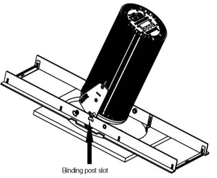
- Insert Fixture:After connecting the fixture to power & data wiring, carefully place the fixture onto the angle support. Hold the fixture gently with binding postsfacing the cross brace. Then move it in.
- Align Fixture to Angle Support:Once moved in, turn the fixture around so that binding posts face the molded slots for the fixture to be placed in.
- Attach Fixture to AngleSupport:Place the mixture slowly into the binding post slot. Adjust the fixture to allow the spring plunger to move into the angle selector.
- Install Trim Ring:Pinch the springs on the Trim ring and insert them into the slots in the rails. Push firmly into place for a tight fit.
- Adjust Angle as Needed:Angle can be adjusted by increments of 5° from 0° to 30°. To change the fixture angle, pull the spring plunger out of the angle slots by pullingthe attached ring to it.Inspire Sloped Ceiling Blind Mount Install Guide V1.3 Model: 632-0990
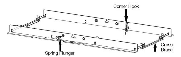 1. Install 2 x Cross brace and 2 x Corner hooks using M3 x 6 screws using the hardware provided, as shown in figure 3.2. Install 1 x Spring Plunger & use a wrench to fully tighten.
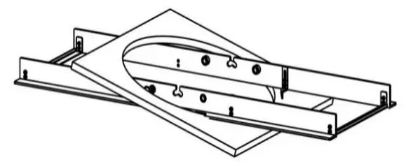
Approvals & Disclaimer
 The information contained herein is offered in good faith and is believed to be accurate. However, because conditions and methods of use of our products are beyond our control, this information should not be used in substitution for customer’s tests to ensure that Chroma-Q products are safe, effective, and fully satisfactory for the intended end-use. Suggestions of use shall not be taken as inducements to infringe any patent. Chroma-Q sole warranty is that the product will meet the Chroma-Q sales specifications in effect at the time of shipment. Your exclusive remedy for breach of such warranty is limited to refund of purchase price or replacement of any product shown to be other than as warranted.
Chroma-Q reserves the right to change or make alterations to devices and their functionality without notice due to ongoing research and development.
The Chroma-Q Inspire range has been designed specifically for the lighting industry. Regular maintenance should be performed to ensure that the products perform well in the entertainment environment.
If you experience any difficulties with any Chroma-Q products please contact your selling dealer. If your selling dealer is unable to help please contact[email protected]. If the selling dealer is unable to satisfy your servicing needs, please contact the following for full factory service:
| Outside North America:Tel: +44 (0)1494 446000Fax: +44 (0)1494 461024[email protected] | North America:Tel: +1 416-255-9494Fax: +1 416-255-3514[email protected] |
report this adFor further information please visit the Chroma-Q website at www.chroma-q.com.Chroma-Q and Uploader are trademarks, for more information on this visit www.chroma-q.com/trademarks.The rights and ownership of all trademarks are recognized.
References
[xyz-ips snippet=”download-snippet”]