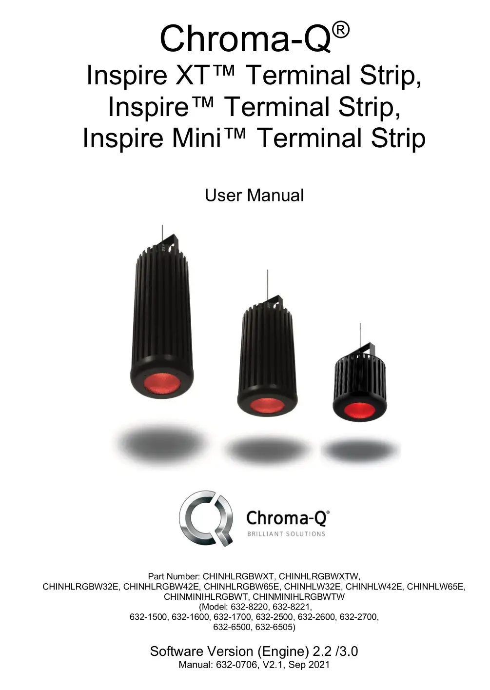
Chroma-Q Inspire/ Inspire XT/Inspire Mini
Terminal Strip User Manual
Warranty Statement
![]()
Chroma-Q warrants to the original purchaser, with proof of purchase, that its delivered products shall be free from defects in material and workmanship under normal use for a period of 36 months from date of shipment.
Chroma-Q will repair, or at its option, provide an equivalent item or replace, the defective product during the stated warranty period. This warranty applies only to the repair or replacement of the product and only when the product is properly handled, installed and maintained according to Chroma-Q instructions. This warranty excludes defects resulting from improper handling, storage, installation, acts of God, fire, vandalism or civil disturbances. Purchaser must notify Chroma-Q in writing within 14 days of noticing the defect. This warranty excludes field labor or service charges related to the repair or replacement of the product.
The warranty contained herein shall not extend to any finished goods or spare parts from which any serial number has been removed or which have been damaged or rendered defective (a) as a result of normal wear and tear, wilful or accidental damage, negligence, misuse or abuse; (b) due to water or moisture, lightning, windstorm, abnormal voltage, harmonic distortion, dust, dirt, corrosion or other external causes; (c) by operation outside the specifications contained in the user documentation; (d) by the use of spare parts not manufactured or sold by Chroma-Q or by the connection or integration of other equipment or software not approved by Chroma-Q unless the Customer provides acceptable proof to Chroma-Q that the defect or damage was not caused by the above; (e) by modification, repair or service by anyone other than Chroma-Q, who has not applied for and been approved by ChromaQ to do such modification, repair or service unless the Customer provides acceptable proof to Chroma-Q that the defect or damage was not caused by the above; (f) due to procedures, deviating from procedures specified by Chroma-Q or (g) due to failure to store, install, test, commission, maintain, operate or use finished goods and spare parts in a safe and reasonable manner and in accordance with Chroma-Q’s instructions (h) by repair or replacement of engines without factory training.
The warranty contained herein shall not apply to finished goods or spare parts which are sold “as is”, as “second-hand”, as used”, as “demo” or under similar qualifications or to Consumables (“Consumables” is defined as any part(s) of goods or part(s) for use with goods, which part(s) of goods or part(s) for use with goods are consumed during the operation of the goods and which part(s) of goods or part(s) for use with goods require replacement from time to time by a user such as, but not limited to, light bulbs).
The warranty contained herein shall not apply, unless the total purchase price for the defective finished goods or spare parts has been paid by the due date for payment.
The warranty contained herein applies only to the original purchaser and are not assignable or transferable to any subsequent purchaser or end-user.
This warranty is subject to the shipment of the goods, within the warranty period, to the Chroma-Q warranty returns department, by the purchaser, at the purchaser’s expense. If no fault is found, Chroma-Q will charge the purchaser for the subsequent return of the goods.
Chroma-Q reserves the right to change the warranty period without prior notice and without incurring obligation and expressly disclaims all warranties not stated in this limited warranty.
Disclaimer
The information contained herein is offered in good faith and is believed to be accurate. However, because conditions and methods of use of our products are beyond our control, this information should not be used in substitution for customer’s tests to ensure that Chroma-Q products are safe, effective, and fully satisfactory for the intended end use. Suggestions of use shall not be taken as inducements to infringe any patent. Chroma-Q sole warranty is that the product will meet the sales specifications in effect at the time of shipment. Your exclusive remedy for breach of such warranty is limited to refund of purchase price or replacement of any product shown to be other than as warranted.
Chroma-Q reserves the right to change or make alteration to devices and their functionality without notice due to our ongoing research and development.
The Chroma-Q Inspire range has been designed specifically for the lighting industry. Regular maintenance should be performed to ensure that the products perform well in the entertainment environment.
If you experience any difficulties with any Chroma-Q products please contact your selling dealer. If your selling dealer is unable to help please contact [email protected]. If the selling dealer is unable to satisfy your servicing needs, please contact the following, for full factory service:
Outside North America:Tel: +44 (0)1494 446000Fax: +44 (0)1494 461024[email protected]
North America:Tel: 416-255-9494Fax: 416-255-3514[email protected]
For further information please visit the Chroma-Q website at www.chroma-q.com.
Chroma-Q and Inspire are trademarks, for more information on this visit www.chromaq.com/trademarks.
The rights and ownership of all trademarks are recognized.
Important Notice:
As per the requirements in the Occupational Safety and Health Administration standards for product approval, please refer to the OSHA web pages http://www.osha.gov/dts/otpca/nrtl/ for information on the list of Nationally Recognized Testing Laboratories (NRTLs) and the scope of recognition.
![]()
Safety information
![]()
Warning!
- Read the user manual before installing and operating the Chroma-Q Inspire. For future reference, keep and use the manual.
- Safety precautions given in user manual must be followed at all times and the manuals of all the devices you connect it to. Observe all the warnings printed on devices and in manuals. Make sure whoever is involved in working on or using the Inspire has carefully read and understood all the safety precautions and lasted warnings.
- Install, connect, operate and service devices only as described in this manual and in connected devices’ manuals and only in accordance with local laws and regulations. All Chroma-Q manuals are available for download from www.chroma-q.com.
- Inspire does not have user-serviceable parts. Refer any operation not described in this manual to [email protected].
If you experience difficulties with any Chroma-Q products please contact your local dealer.If your local dealer is unable to help then please contact [email protected].If you are having trouble finding what you are looking for on our website, then contact our Chroma-Q marketing department by sending an email to [email protected].
PROTECTION FROM ELECTRIC SHOCK
- Use only the cables specified in this manual and on the Chroma-q website at www.chromaq.com to interconnect devices in the installation. If the specified cables are not long enough for an intended cable run, consult Chroma-Q for assistance in finding or creating a safe alternative solution.
- Provide a means of locking out AC mains power that allows power to the installation to be shut down and made impossible to reapply, even accidentally, during work on the installation.
- Shut down power to the installation during service and when it is not in use.
- Before applying power to the installation, check that all power distribution equipment and cables are in perfect condition and rated for the current requirements of all connected devices.
- Isolate the installation from power immediately if any product, power cable or power plug is in any way damaged, defective or wet, or if it shows signs of overheating.
- Do not immerse an Inspire fixture in water or expose it to high-pressure water jets.
PROTECTION FROM BURNS AND FIRE
- The Inspire is cooled passively by natural air convection. Provide adequate clearance for airflow around the fixtures.
- Do not operate the Inspire if the ambient temperature (Ta) exceeds 40° C (104° F).
- Do not modify the Inspire in any way not described in this manual or install other than genuine Chroma-Q parts.
- Use only accessories approved by Chroma-Q.
PROTECTION FROM INJURY
- Ensure that the installation hardware and supporting surface or structure can hold at least 10 times the weight of all the devices they support.
- Block access below the work area and work from a stable platform whenever installing, servicing or moving the Inspire.
- As soon as work is completed, check that all hardware and components are securely fastened to supporting structures.
- Make sure there are no flammable materials close to the product during operation.
- Avoid direct eye exposure to the light source while the product is on.
- Never try to repair the product. Repairs carried out by unskilled people can lead to damage or malfunction. Please contact the nearest authorized dealer or contact [email protected].
![]() Keep this User Manual for future consultation. If this product is used by another user, be sure that they also receive this document.
Keep this User Manual for future consultation. If this product is used by another user, be sure that they also receive this document.
Product overview
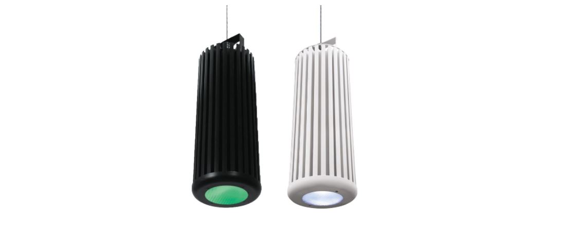
The Chroma-Q® Inspire™ Terminal strip LED house light is a powerful multi-purpose creative lighting tool that utilises some of the innovative core technologies found in the incredibly popular Chroma-Q Color Force™ range. The Inspire provides a choice of beautiful whites, soft pastels and bold saturates – all from one fixture. By incorporating industry standard DMX-512 control to the external control box, the Inspire is able to integrate seamlessly with an existing DMX infrastructure and can be controlled by any DMX supported lighting console. With fully homogenised color mixing and a choice of three different lens options, the Inspire provides an excellent selection of stunning mixed colors and ‘true’ whites, with no unsightly color separation shadows. It also features an energy-efficient compact LED design providing reduced maintenance and running costs. Each fixture is equipped with a built-in power supply which can be controlled remotely from the Inspire External Control Box through the ANSI E1.11 USITT DMX 512-A protocol.
Note: HANDHELD light METERS
Handheld Light Meters provide a limited measuring range for LED fixtures, which may result in inconsistent and unreliable measurements.
All photometric values listed in this document are based on testing and measurements conducted by certified independent laboratories with reference to the IES standards.
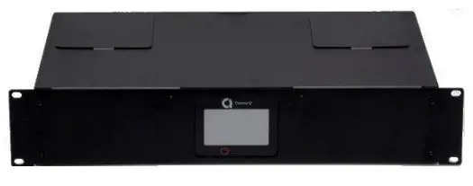
Inspire External Control Box
The Inspire External Control Box is a 19” rack mount external remote addressing unit for the control of the Inspire Terminal Strip fixture via DMX 512.Three data output ports are available for the control of 128 daisy-chained fixtures from each port. (See cabling section for more details) DMX data input and through connections from an external DMX control console are via XLR 5-pin.The Inspire External Control Box is built with Plug-in Terminal Block connectors for AC power input, Emergency power input, control data output signals and XLR DMX in and thru connections.
Operation
Unpacking the Units
Table 1: The Inspire Terminal Strip package includes:
We recommend that you keep the original packaging in case the item needs to be returned
Cabling system
The Inspire External Control Box has 3 control data outputs (Port 1, 2, 3). Each control data output provides remote control for 128 daisy-chained Inspire Terminal Strip fixtures. The maximum length of the DMX cable from each data output of the External Control Box to the first Terminal Strip fixture must not exceed 500 ft (152 m).
Each Inspire Terminal Strip fixture has its own signal buffer with a bypass relay. This means the signal transmitted from the UL924 Control box is being regenerated at each fixture. Therefore, the number of fixtures on a single link can exceed the typical limits, in theories up to 128 fixtures could be daisychained. For ease of troubleshooting and to minimize the single point failure factor, it is suggested to divide the fixture count per link over the three outputs of the UL 924 Control box. In case of power failure on a fixture, an internal relay will let the data pass through. It is also important to know that the signal coming out of the UL924 Control Box cannot be split using Y cables or DMX opto-splitter. However, Opto-Splitters or DMX buffer can be used to isolate links between fixture and control box.
Because the signal is being regenerated at each fixture, the first fixture on the link must have a 120 Ω resistor (terminator) between the + and – on the input side of the fixture.
If the cable length between the subsequent fixtures on the link is less than 100 feet (30 meters) no additional terminator is needed. If longer, a 120 Ω resistor can be added at the fixture data input where the longer cable connects.
Figure 1: System Diagram

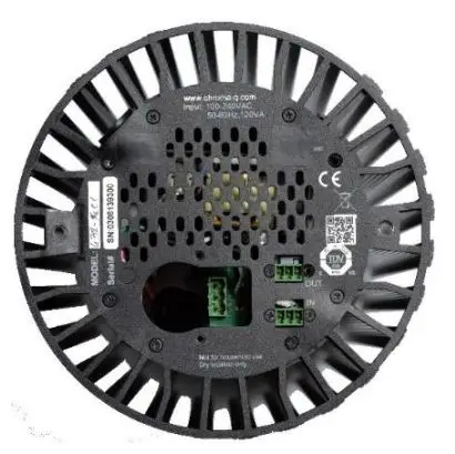
Figure 2: Bottom view of the fixture
Inspire Terminal Strip fixture wiring:
To connect the wiring of the AC power input cable:
- A Connector Box is provided with the fixture (Figure 4), and is not attached to the fixture. The Connector Box must be mounted as described in the following steps.
- To avoid pressure on connector and faulty connection, the power cable should be soft like SJOW cable type. In case the cable is rigid, a half inch NPT connector must be used to avoid tension on the cable / connector attached to the light fixture.
- A Power Input Terminal Block Plug with three wires (Figure 7) is supplied with the Inspire Terminal Strip fixture. However, in case different wires are to be used, ensure the wire connection (Figure 3) and wire stripping length is correct (Figure 7), and to use only soft stranded wires to the terminal block plug. Solid core wire should never be used directly on the terminal block.
- Insert the power cable with the appropriate ½” NPT Connector or Cable Strain Relief through the Connector Box (Figure 4). The hole on the connector box has a Suitable dimension to attach a ½” NPT connector on it. The Power Input Terminal Block Plug has three soft wires attached to it. Attach the provided wires to the wiring for the AC power input cable with Quick Connectors or Marret Connectors (Figure 4).
- Put the Quick / Marret Connectors inside the Connector Box. Plug the wired Terminal Block Plug into the Power Input Terminal Block Header (Figure 4).
To connect the wiring of the control data cables:
- Connect the DMX control data cables from the Inspire External Control Box / another Inspire light fixture to the Data Input Terminal Block Plug. Ensure that the bare wire is not visible. Some insulation of the wire must be inside the hole. The maximum strip length is 4 mm (Figure 8).
- The control cable connected to the first Inspire Terminal Strip fixture from each Data Output of the External Control Box MUST be terminated with a 120 Ω resistor (Figure 10). For details, see Inspire Terminal Strip DMX Cable Termination on the next section.
- Plug Data Terminal Block Plug into the Terminal Block headers at the rear of the fixture (Figure 5).
- Put the Connector Box in place and fasten the Connector Box with capacitive screw (Figure 6).
- Tighten the ½” NPT Connector clamp/ gland.
Note: The control cable connected to the first fixture from each data output MUST be terminated with a 120 Ω resistor. Terminal blocks with resistors installed are included in the External Control Box. See Inspire Terminal Strip Data Cable Termination on the next section.
Figure 3: AC Power Cable Wiring
Table 2: Power cable color code
Figure 4: Power cable connection
Figure 5: Data Cable Wiring
Figure 6: Back Plate of Inspire Terminal Strip after connection
Wire Strip Length
The wire must be stripped to the proper dimension to ensure correct insertion depth in the connector. Excessive conductor will be exposed if the strip length is too long and entrapment of the insulation or improper termination will result if the strip length is too short.
The wire must be inserted into the wire hole until the insulation is even with the housing at the wire hole opening. The screw must be hand tightened with the proper screwdriver to within the torque provided.
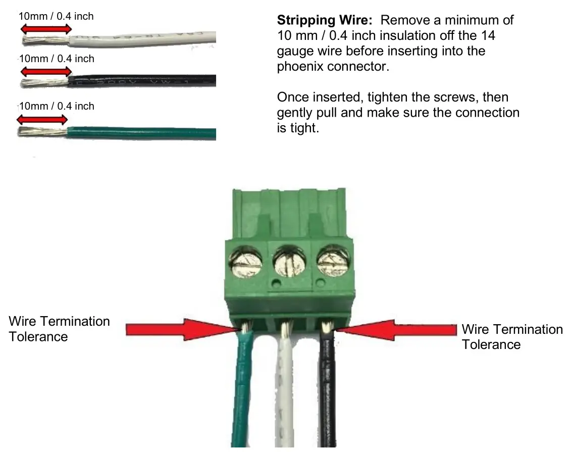
Figure 7: Wire Stripping for Power Connection
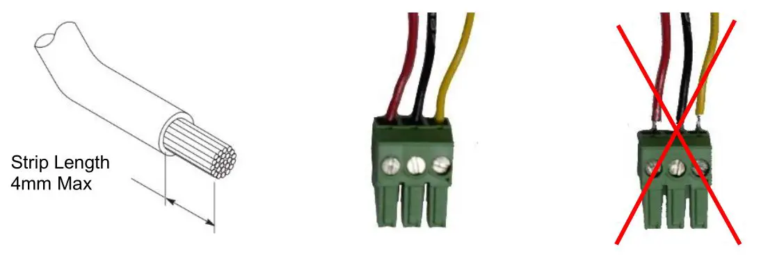
Figure 8: Wire Stripping for Data Connection
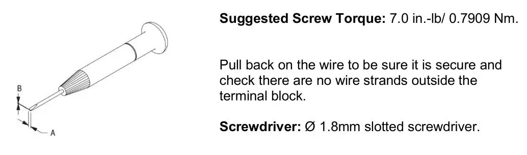
Figure 9: Recommended screw size and torque
IMPORTANT! Inspire Terminal Strip Data Cable Termination:
The data cable connection from each Data Output of the External Control Box to the first Inspire Terminal Strip fixture MUST be terminated with a 120 Ω resistor. Insert a 120 Ω resistor into the Terminal Block Plug (Data Plus and Data Minus) and then plug into the data IN header of the first Inspire Terminal Strip fixture. (Figure 10)
Terminal blocks with resistors installed are included in the External Control Box.
Note: In order to eliminate line noise, be sure to terminate the data common wire.
Figure 10: Input Data Cable Wiring to first Inspire Terminal Strip Fixture
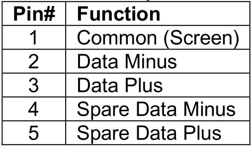
Table 3: XLR 5-pin Cable:
Note: Refer to ESTA (Entertainment Services and Technology Association) technical standards program (TSP) documents (ANSI E1.27-2 -2009 (R2014)) for more detail about recommended practice for permanently installed control cables for use with ANSI E1.11 (DMX512-A) and USITT DMX512-1990 products or Click on the link below.http://tsp.esta.org/tsp/documents/published_docs.php
Important Notice:
The maximum length of the DMX cable from each data output of the Inspire External Control Box to the first Terminal Strip fixture is 500 ft (152 m).The use of an opto-splitter for DMX signal distribution is highly recommended when several control boxes are not plugged into the same power source.
Mounting
The InspireTM Terminal Strip fixture is built with a mounting bracket for overhead hanging applications.The mounting bracket has a 1/2″ hole suitable for M10 & M12 bolts. Secure the fixture with a safety cable. A provision for a fixing hold is built into the fixture.
Other mounting options, such as a yoke, or recessing mounting kits are available. Consult your local representative or the Chroma-Q website for more details
Table 4: Optional Mounting Kits and Accessories
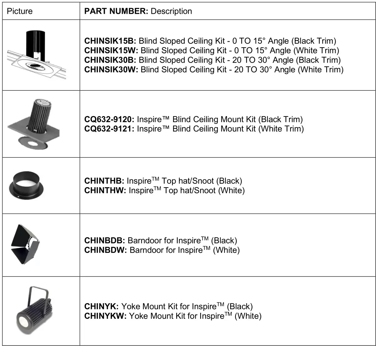
For further information, consult your local representative or please visit the Chroma-Q website athttps://chroma-q.com/support/downloads product download section for installation instructions and product support material download.
Optics
The Inspire XT Terminal Strip fixture is built with a permanent 32° lens. Where wider beam spreads are required, use the, Spread Lens Kit provided. The diffusion film is installed between the permanent lens and the bezel. Consult the QSG in the lens kit for more detailed lens installation instructions. The beam angles are:NO LENS ~ 32°, Medium lens ~ 42°, Wide lens ~ 65°.
The Inspire Terminal Strip can be built with either Narrow, Medium or Wide lens. The beam angles are: Narrow: ~32°; Medium: ~42°; Wide: ~65°.The Inspire Mini Terminal Strip is built with wide lens with a beam angle of approximately ~65°.The Optional Spreader Lens Kit is available for changing the beam angle of any Inspire Light Fixture.
Control
The Inspire Terminal Strip fixture is controlled remotely through the Inspire External Control Box via DMX protocol. For control menu details see the User Manuals for the Inspire External Control and Inspire External Control UL924 units.
Thermal Performance
The internal cooling system of the Inspire Terminal Strip is by convection and the fixture is built with automatic protection. The fixture’s automatic protection reduces the output when the internal temperature reaches the maximum limit due to extreme ambient conditions.
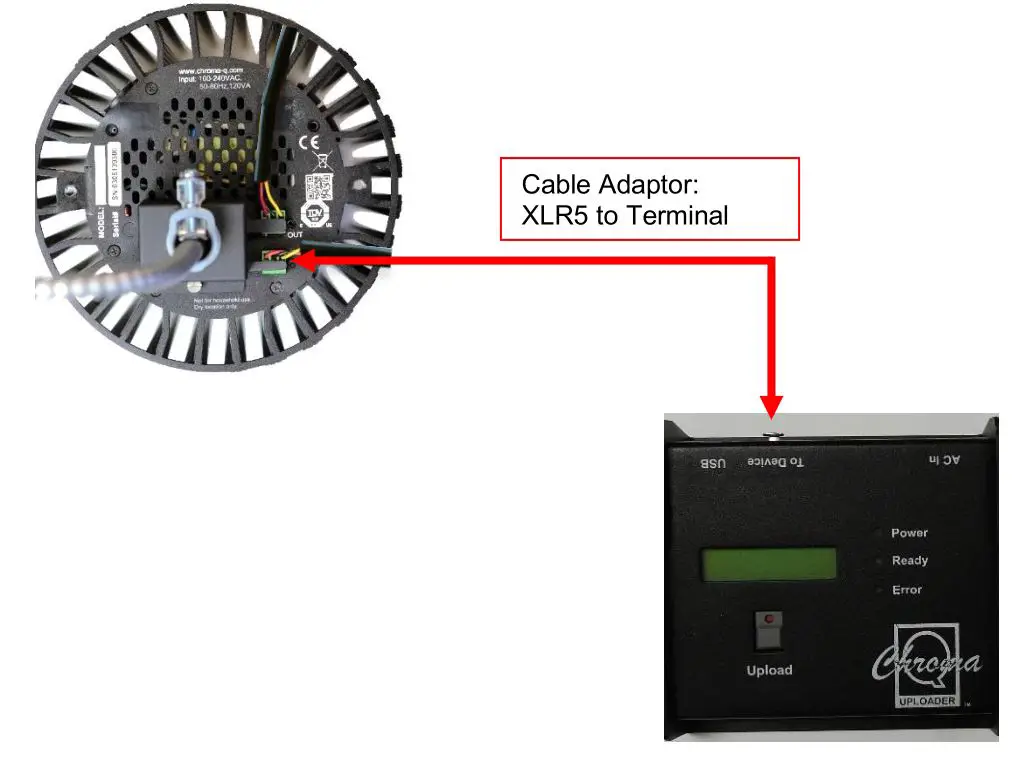
Updating the LED engine software
The software for the LED engine module of the Terminal Strip can be uploaded directly into the fixture through the Uploader using an XLR5 to Terminal Block cable adaptor. The upload process can be performed to one fixture at a time only. (See diagram below)
- Download and extract the current software revision from https://chromaq.com/support/downloads under the “Software” column.
- Connect the Chroma-Q Uploader to your PC.
- Erase the previous file and copy the “module_rgbw1_Inspire_v2.2.hex” into the Uploader.
- Connect the Uploader to the fixture with a XLR 5-pin to Terminal Block cable adaptor.
- Power-up the fixture.
- The Uploader display shows the software name and version, and “Ready”.
- Press the GO button once to execute the uploading.
- The Red indicator light on the GO button blinks and the Uploader display shows a simulated arrow indicating the uploading process.
- All the green LEDs of the fixture will light up (low intensity) to indicate completion of a successful Upload.
- The Uploader display shows “DONE” upon completion of the upload.
- Power-cycle the fixture.
- Repeat step 6 to step 10 if the uploading process is interrupted (power and/or data).
(For more detail, see the Quick Start Guide of the Chroma-Q Uploader)
**Important:
Use the firmware V3.0 (File Name: Inspire_XT_Engine__PCB_Rev_C__firmware_ver_3.0, for the following S/N or higher: Model 632-8200 S/N:306244977, Model: 632-8205 S/N: 306247708, PCB 901-0256 RevC.
Use the firmware V2.2 (File Name: Inspire_XT_Engine__PCB_Rev_A__firmware_ver_2.2) for the following S/N or lower: Model: 632-8200 SN:306244976, Model 632-8205 SN: 306247707; PCB 901- 0256 RevA
Troubleshooting
Troubleshooting is a process of elimination. First, rule out the other field factors (i.e. bad connections, faulty cables and power supplies). For technical support and/or parts, please contact your selling dealer or the offices listed in this manual.
Table 5: Troubleshooting of Inspire Terminal Strip fixture
Specification
Technical Specifications
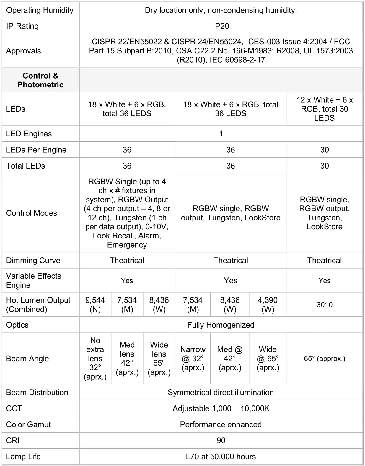
**For exact measurements please refer to the line drawings below
![]()
Drawings – Dimensions
Figure 10: Line Drawing Inspire XT Terminal Strip
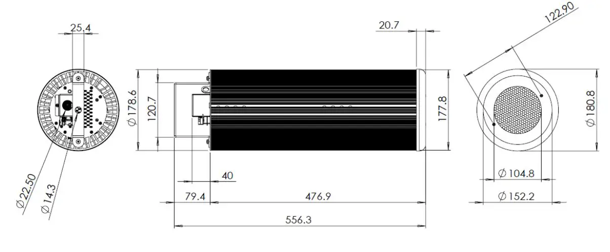
Figure 11: Line Drawing Inspire Terminal Strip

Figure 12: Line Drawing Inspire Mini Terminal Strip
Maintenance
With care, the Inspire Terminal Strip fixture and external Control Box requires little maintenance. However, as the unit is likely to be used in a stage environment, we recommend periodical internal inspection and cleaning of any resulting dust and cracked oil residue.
report this adDo not spray liquids on the front or rear panel. If the front enclosure requires cleaning, wipe with a mild detergent on a damp cloth.
References
[xyz-ips snippet=”download-snippet”]