CITY THEATRICAL Multiverse Receiver Card 2.4GHz 5906 User Manual
Foreword
Safety NoticeThis product is designed for use in dry locations only. Exposure to rain or moisture may cause damage to the transceiver and increase risk of electrical shock.Check all external wiring before applying power.
Introduction
While Multiverse Modules are circuit board mounted devices used by professional lighting manufacturers, City Theatrical’s Multiverse Receiver Card, 2.4GHz (P/N 5906) can be used by anyone to implement wireless DMX/RDM into their projects or equipment in a simple way. 5906 Multiverse Receiver Cards are full Multiverse receivers for the 2.4GHz band (P/N 5907 is for the 900MHz band) without the housing, XLR connectors, and user interface as used in wireless DMX receiving products like Multiverse Node and Multiverse SHoW Baby. Multiverse Receiver Cards include an internal antenna and a U.FL connection to an optional external antenna. Configuration is done via City Theatrical’s USB Configuration program for PC/MAC. This product is designed and built in the USA by City Theatrical.
Features
- Supports ANSI E1.11 DMX512-A and E1.20 RDM
- DMX RS-485 driver on board with ±60V protection
- Signal Quality LEDs on board and external connections
- SHoW ID RGB LED on board and external connections
- Multiverse Band LED on board and external connections
- Wide input voltage range, 5V to 30Vdc
- Footprint 50mm(2”) x 38mm(1.5”)
- +3.3Vdc output to power low current hosts
- Configurable over USB Micro-B connector
- Firmware updatable over USB Micro-B connector
- Advanced Mode features:
- 0-10V output
- Four PWM control outputs
Part Numbers
| Part # | Description |
| 5906 | Multiverse Receiver Card, 2.4GHz |
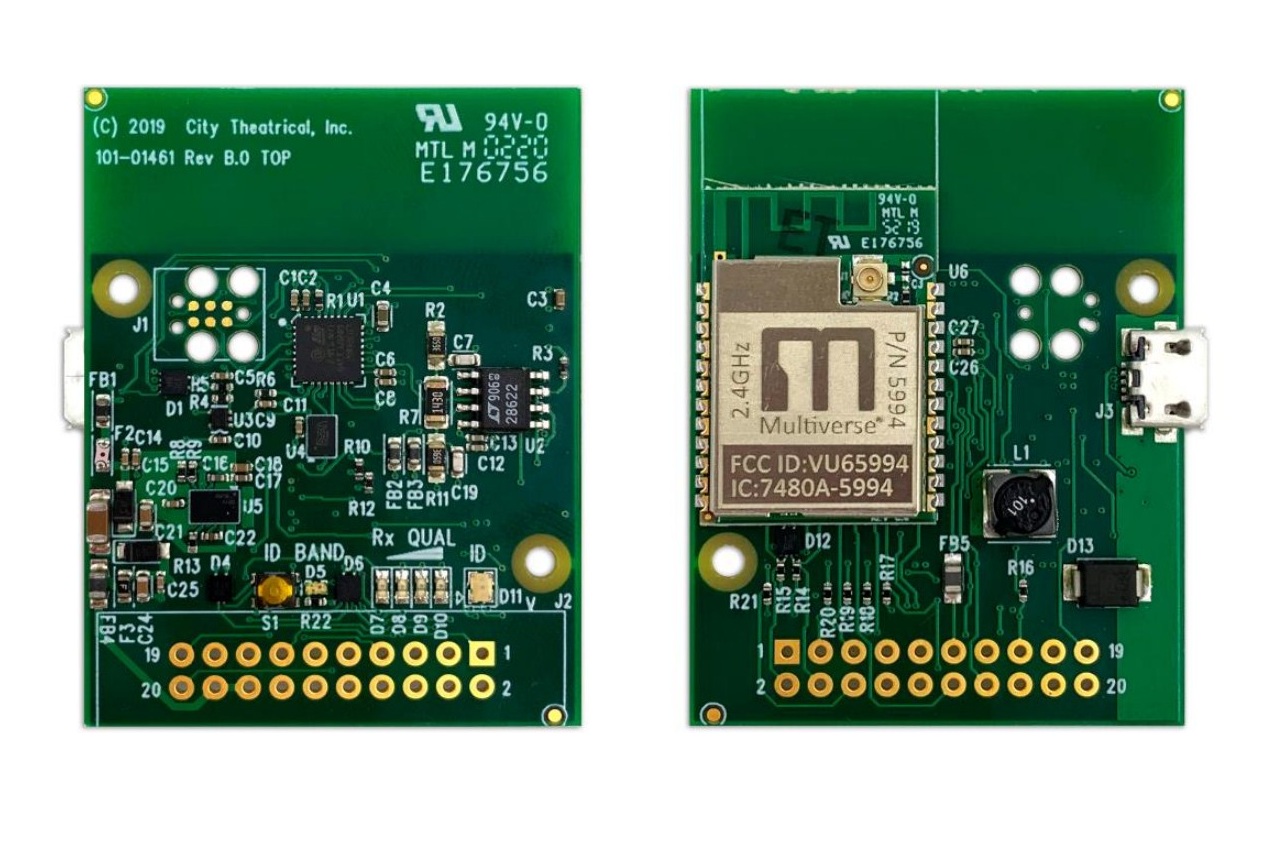
Product Detail
Product is shown larger than actual size.
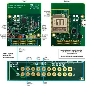
Dimensions (with internal antenna)*: 2.0″ (50mm) L x 1.5″ (38mm) W x 0.25″ (6.4mm) H *Shown here larger than actual size
Figure 1: Top and Bottom Detail with Basic Signal Pinout for Wireless DMX*
Specifications
Table 2: Physical Characteristics
| Specifications | Description |
| Frequency | 2.4GHz |
| Universe(s) | 1 |
| Size (with internal antenna) | 2.0″ (50mm) L x 1.5″ (38mm) W x 0.25″ (6.4mm) H |
| Antenna | Internal/External |
| Construction | PCB assembly |
| Power/Data Connector | 20-Pin 2×10 0.100-inch header, male |
| Radio Information | |
| Voltage Range | 5-30VDC |
| Broadcast Power | Antenna dependent; 100mW EIRP |
| Broadcast Modes | Adaptive, Full, Low, Mid, High, Max |
| Ethernet Protocols | N/A |
| SHoW IDs | Multiverse: 147; Neo: 70 |
| Latency | 4ms average |
| RF Sensitivity | -95dBm |
| RDM Features | RDM Proxy, RDM |
| Product Information | |
| Configuration | City Theatrical USB Configuration program PC/MAC |
| Use Environment | Indoor |
| Warranty | One year |
| Compliance | Pre compliance reports available for integrators |
Configuration for Wireless DMX (Basic Mode)
Basic Mode will describe wireless DMX reception with wired DMX output. In its simplest form, the receiver card receives multiverse wireless DMX/RDM and outputs DMX/RDM as a differential pair on pins 11 thru 13 of the interface connector. For Advanced Mode (see page 11), users can optionally turn on a 0-10V output and/or PWM outputs and set starting DMX addresses for them. In all cases, the user interface presented is the same.
The Multiverse receiver card can be configured with RDM through a Multiverse Transmitter, Multiverse Node, or Multiverse SHoW Baby, or with the USB connector using the free City Theatrical USB Configurator program. All settings can be changed via the USB connection. RDM settings are only appropriate to what an end user will need to adjust. Feature settings are set by the integrator via the USB connector only.An easy way to apply power to the Multiverse Receiver Card for configuration (before any connections are wired to the card) is through the USB Micro-B connection.
Configuring Using RDMTo configure using RDM such as with a City Theatrical DMXcat® , a City Theatrical Multiverse Transmitter, Multiverse Node, or Multiverse SHoW Baby must be used to broadcast to your Multiverse Receiver card, and RDM configuration is performed through the Transmitter with the Multiverse Receiver Card as a connected wireless device. See Resetting Factory Defaults below.
Configuring Using City Theatrical USB Configurator for PC/MacWhen connecting the USB Micro-B connector to a PC or MAC, the receiver card will act as a virtual serial port. Use the City theatrical USB Configurator program, downloadable from the CTI website, to configure the card. Using the USB Configurator program you can easily set the SHoW ID, optional SHoW KEY, output power, and make the selection of an external antenna if you are using one. Other settings not related to basic wireless DMX will be described in the Advanced Features section of this manual.
Resetting Factory DefaultsFactory defaults may be manually reset by holding the SHoW ID Selector Switch for five seconds. The four signal quality lights will flash in unison to show the completion of the reset. Factory defaults as seen on the City Theatrical USB Configurator program are seen below. These settings are found on the Basic Info tab and Manufacturer’s Settings tab in RDM.
- DMX tab
- RDM traffic disabled
- DMX port label: Default Port Label
- Universe: 1
- Multiverse tab
- SHoW ID: 24250
- Antenna Selection: Internal
- Output Power: Max
- SHoW Key (0-500): 0
- Info tab
- Device Label: Device Label
- DMX Fail Mode
- Hold last look before bumping to level: infinite
- Hold level before bumping to black: infinite
- Advanced tab
- PWM Output: Disabled
- 0-10V Output: Disabled
Band LED/SHoW ID Selector SwitchThe 5906 can receive in either 2.4GHz SHoW DMX Neo mode or 2.4GHz Multiverse mode (for Multiverse 900MHz, use P/N 5907). The band LED indicates whether the receiver card is currently listening to a Multiverse SHoW ID (green) or a SHoW DMX SHoW ID (yellow). See Table 3 below.Pressing the SHoW ID Selector Switch button will first cycle through six Multiverse SHoW IDs, the Band light will be green and the ID light will cycle through the six ID colors in Table 4 below. If you continue pressing the SHoW ID Selector Switch the Band light will change to yellow and you will begin to cycle through the six SHoW DMX Neo SHoW IDs.
Table 3: Band LED Colors
| Color | Band |
| Green | Multiverse 2.4GHz |
| Yellow | SHoW DMX Neo 2.4GHz |
ID/Status LED
When the ID/Status light is blinking, no DMX is being received. It turns solid when receiving DMX.
Table 4: SHoW ID Colors
| ID Color | SHoW ID
Band: Green |
SHoW ID
Band: Yellow |
Broadcast Location |
| Green | 24250 | 201 | Adaptive hopping |
| Cyan | 24102 | 102 | Full bandwidth hopping |
| Magenta | 24112 | 117 | Low band hopping |
| White | 24122 | 133 | Mid band hopping |
| Red | 24132 | 149 | High band hopping |
| Yellow | 24142 | 165 | Max band hopping |
| Blue | RDM | RDM | SHoW ID set via RDM |
Rx Quality LEDs
There are four LEDs in this group that represent the quality of the wireless signal received. All four LEDs will be lit when the receive quality is at is maximum. Orient the antenna of the device to produce as many lit LEDs as possible. For best performance, at least two LEDs should be lit.
Table 5: Pinout Descriptions for Wireless DMX (Basic Mode)
| Pin | Type | Signal Name | Function | Notes |
| 1 | ||||
| 2 | ||||
| 3 | ||||
| 4 | ||||
| 5 | ||||
| 6 | ||||
| 7 | ||||
| 8 | ||||
| 9 | ||||
| 10 | ||||
| 11 | GND | DMX_C | DMX Common | |
| 12 | O | DMX_DM | DMX Data Minus | |
| 13 | O | DMX_DP | DMX Data Plus | |
| 14 | ||||
| 15 | ||||
| 16 | ||||
| 17 | GND | GND | Signal Ground | |
| 18 | PWR | Vin | +5-30V DC input | |
| 19 | ||||
| 20 |
Prefix
0 (or blank) Neo mode at 2.4GHz The rest of the show ID is the same as on Neo products. 24 2.4GHz
Data Rate
Faster data rates provide more DMX universes. Slower data rates travel longer distances and provide more immunity to interference.
| 2.4GHz: | Universes |
| 1 | 1 |
| 2 | 2 |
| 3 | 5 |
Band
Specifies which sections of the wireless band the frequency hopping utilizes.
- 0. Use full range
- 1. Use only low band channels
- 2 Use only mid band channels (available for 1Mbps only).
- 3 Use only high band channels
- 4 Use only extreme high band to avoid WiFi (2.4GHz only. May limit power output).
- 5 Adaptive hopping. Avoids busy channels by analyzing spectrum (2.4GHz only).
Note: Not all combinations of digits are possible and unused numbers are reserved for future use.Note: SHoW ID, SHoW Key (if used) and Universe must match between Transmitter and Receiver Cards.Figure 2: Multiverse SHoW ID
SHoW KeyThe SHoW Key setting allows a user to enter a key to privatize their SHoW ID from another system on the same SHoW ID. SHoW IDs and SHoW Keys need to match in order for receivers and transmitters to talk to each other. Keeping your SHoW Key private will provide a level of security to your Multiverse system from un-authorized use. It is not recommended to use different SHoW Keys in a system that uses multiple Multiverse Nodes as Transmitters on the same SHoW ID. The range is 0 (Default) to 500.
Table 6: SHoW IDs and SHoW Keys
|
Situation |
Condition | Outcome | |
|
Same SHoW Key |
with | Different SHoW IDs | OK |
| Different SHoW Keys | with | Same SHoW IDs |
Not OK |
| Different SHoW Keys | with | Different SHoW IDs |
OK |
Output Power
Output power may be user selected as Low, Med, Hi, or Max. It is a best practice to use the least amount of output power to achieve a successful show. You can monitor signal quality on the receiver’s user interface screen LED bargraph, or via RDM. Default iMax. Note: Output power on a receiver refers to RDM transmission.
Antenna SelectionThis value sets the onboard Multiverse Radio configuration to optimize for the antenna being used. In most situations the Multiverse Receiver Card, 2.4GHz will use the internal antenna. Only change this value if an external antenna is connected.
Configuration for 0-10V or PWM Output (Advanced Mode)
Advanced mode allows the use of 0-10V and PWM outputs, setting the starting DMX addresses for those outputs, as well as relocating LED indicators in remote positions.
0-10V FeatureThe 0-10V feature provides one 0-10V control signal output for controlling architectural lighting devices. This feature can either sink or source control voltages without the need to configure sink/source.
PWM FeatureThe PWM feature repurposes the receive quality LEDs into PWM outputs. These are low current control outputs and are not intended to drive lighting loads. The feature provides four PWM outputs. The PWM output is linear in respect to the DMX control input and has a resolution of 8 bits, using one DMX slot per output. Refer to Table 8 for DMX addressing.
Table 7: Pinout Descriptions in Advanced Mode
|
Pin |
Type | Signal Name | Function | Notes |
| 1 | O | LED_RXQ2 | Rx Quality LED Medium / PWM 2 | |
|
2 |
O | LED_ID_R | Red SHoW ID RGB LED | |
| 3 | O | LED_RXQ3 | Rx Quality LED Hi / PWM 3 | |
|
4 |
O | LED_ID_G | Green SHoW ID RGB LED | |
| 5 | O | LED_RXQ4 | Rx Quality LED Max / PWM 4 | |
|
6 |
O | LED_ID_B | Blue SHoW ID RGB LED | |
| 7 | O | LED_BAND | Band LED Anode | |
|
8 |
PWR | Vout | +3.3Vdc regulated output | Max current 200mA |
| 9 | GND | GND |
Signal Ground |
|
|
10 |
PWR | Vout | +3.3Vdc regulated output | Max current 200mA |
| 11 | GND | DMX_C | DMX Common | |
|
12 |
O | DMX_DM | DMX Data Minus | |
| 13 | O | DMX_DP |
DMX Data Plus |
|
|
14 |
I | BUTTON | SHoW ID Button | |
| 15 | O | LED_RXQ1 | Rx Quality LED Low / PWM 1 | |
|
16 |
PWR | Vin | +5-30Vdc input | |
| 17 | GND | GND | Signal Ground | |
|
18 |
PWR | Vin | +5-30V DC input | |
| 19 | O | ZERO_TEN | 0-10V output | |
|
20 |
O | LED_BAND_PWM |
Band LED Cathode |
Signal DescriptionsBelow each pin is described in detail.
Pin 1 – LED_RXQ2This pin operates in one of two modes. When the PWM feature is disabled, this pin is the medium receive quality LED control line. When PWM feature is enabled, this pin is PWM output two.
To connect an external LED to this pin, remove R18 from the card and connect this pin to the cathode of the external LED. The sink current for the external LED should not exceed 10mA. To use the pin as a PWM control output, use the USB configurator to enable the feature and connect pin to the control input of the host product. See Table 8 for channel assignments. The DMX address is changed using RDM or the City Theatrical USB Configurator program.The PWM feature is configurable using the USB configurator only.
Pin 2 – LED_ID_RThis pin is the red color of the RGB SHoW ID LED. To connect an external RGB LED, remove R15 from the card and connect this pin to the red cathode of a common anode RGB led. The sink current for the external LED should not exceed 10mA.
Pin 3 – LED_RXQ3This pin operates in one of two modes. When the PWM feature is disabled, this pin is the high receive quality LED control line. When PWM feature is enabled, this pin is PWM output three. To connect an external LED to this pin, remove R19 from the card and connect this pin to the cathode of the external LED. The sink current for the external LED should not exceed 10mA. To use the pin as a PWM control output, use the USB configurator to enable the feature and connect pin to the control input of the host product. See Table 8 for channel assignments. The DMX address is changed using RDM or the City Theatrical USB Configurator program. The PWM feature is configurable using the USB Configurator program only.
Pin 4 – LED_ID_GThis pin is the green color of the RGB SHoW ID LED. To connect an external RGB LED, remove R14 from the card and connect this pin to the green cathode of a common anode RGB led. The sink current for the external LED should not exceed 10mA.
Pin 5 – LED_RXQ4This pin operates in one of two modes. When the PWM feature is disabled, this pin is the max receive quality LED control line. When PWM feature is enabled, this pin is PWM output four. To connect an external LED to this pin, remove R20 from the card and connect this pin to the cathode of the external LED. The sink current for the external LED should not exceed 10mA.To use the pin as a PWM control output, use the USB configurator to enable the feature and connect pin to the control input of the host product. See Table 8 for channel assignments. The DMX address is changed using RDM or the City Theatrical USB Configurator program. The PWM feature is configurable using the USB Configurator Program only.
Pin 6 – LED_ID_BThis pin is the blue color of the RGB SHoW ID LED. To connect an external RGB LED, remove R21 from the card and connect this pin to the blue cathode of a common anode RGB led. The sink current for the external LED should not exceed 10mA.
Pin 7 – LED_BANDThis pin is part of a two-pin connection to a bi-color LED (Green/Yellow). The pin connects to the anode of the yellow and the cathode of the green. For more information about how this LED is used, refer to Table 3.
Pin 8 – +3.3VThis pin provides 3.3Vdc to the host PCB. It is also tied to pin 10.
Pin 9 – GNDThis pin is circuit common for the receiver card.
Pin 10 – +3.3VThis pin provides 3.3Vdc to the host PCB. It is also tied to pin 8.
Pin 11 – DMX_CThis is the DMX common pin. It usually connects to pin 1 of a 5 pin XLR. It connects to circuit common thru a ferrite bead. Do not use this as the only ground for the card.
Pin 12 – DMX_DMThis is the DMX data minus pin. It usually connects to pin 2 of a 5 pin XLR. The pin is protected from overvoltage line faults to ±60V and has an extra common mode of ±25V.
Pin 13 – DMX_DPThis is the DMX data plus pin. It usually connects to pin 3 of a 5 pin XLR. The pin is protected from overvoltage line faults to ±60V and has an extra common mode of ±25V.
Pin 14 – ButtonThis pin, when temporarily shorted to circuit common, will advance the SHoW ID as described in the Band LED/ SHoW ID Selector Switch section on page 7.
Pin 15 – LED_RXQ1This pin operates in one of two modes. When the PWM feature is disabled, this pin is the low receive quality LED control line. When PWM feature is enabled, this pin is PWM output one.To connect an external LED to this pin, remove R16 from the card and connect this pin to the cathode of the external LED. The sink current for the external LED should not exceed 10mA. To use the pin as a PWM control output, use the City Theatrical USB Configurator program to enable the feature and connect pin to the control input of the host product. See Table 8 for channel assignments. The DMX address is changed using RDM, or the City Theatrical USB Configurator program. The PWM feature is configurable using the USB Configurator program only.
Pin 16 – VinThis is the supply pin for the receiver card. It has an input range of 5V to 30V DC. A minimum of +11V is required to use the 0-10V feature, as this voltage is the supply for the 0-10V op-amp. This pin is also tied to pin 18.
Pin 17 – GNDThis pin is circuit common for the receiver card.
Pin 18 – VinThis is the supply pin for the receiver card. It has an input range of 5V to 30V DC. A minimum of +11V is required to use the 0-10V feature, as this voltage is the supply for the 0-10V op-amp.This pin is also tied to pin 16.
Pin 19 – ZERO_TENThis is the 0-10V output when enabled. See Table 8 for channel assignments. The DMX address is changed using RDM or the City Theatrical Configurator program . This output can sink or source current, thus it can be used in both theatrical and architectural installations. Maximum current should not exceed 15mA.Pin 20 – LED_BAND_PWMThis pin is part of a two pin connection to a bi-color LED (Green/Yellow). The pin connects to the cathode of the yellow and the anode of the green. For more information about what the LED is used for refer to the PWM Feature section on page 11.To connect an external LED to this pin, remove R17 and R22. The drive current for this pin should not exceed 10mA.
DMX AddressingThe receiver card can operate as a DMX output only receiver (Basic Mode); DMX output receiver with one 0-10 output, DMX output receiver with four PWM outputs or a DMX output receiver with one 0-10 output and four PWM outputs (Advanced Mode). Refer to Table 8 for addressing information.
Table 8: DMX Address Map
| 0-10
Enabled |
PWM
Enabled |
0-10
Offset |
PWM 1
Offset |
PWM 2
Offset |
PWM 3
Offset |
PWM 4
Offset |
| No | No | |||||
| Yes | No | Start + 0 | ||||
| No | Yes | Start + 0 | Start + 1 | Start + 2 | Start + 3 | |
| Yes | Yes | Start + 0 | Start + 1 | Start + 2 | Start + 3 | Start + 4 |
Specifications
Table 9: Absolute Maximum Ratings1
| MIN | MAX | UNIT | |
|
Supply Voltage |
5 | 30 | V |
| Voltage on any pin | -0.3 | 3.3V + 0.3 |
V |
| Storage Temperature | -40 | 150 |
°C |
- Stresses beyond those listed under Absolute Maximum Ratings may cause permanent damage to the module. There are stress ratings only, and functional operation of the device at these or any other conditions beyond those indicated under Recommended Operating Conditions is not implied. Exposure to absolute maximum-rated conditions for extended periods may affect device reliability.
Table 10: Physical Characteristics
| UNIT | ||
| Size | 50 x 38 | mm |
| I/O Interface | 2×10 0.100” PCB land pattern | |
| Antenna Connector | U.FL/IPEX | |
| Packaging | Individual Anti-Static bag |
Table 11: Recommended Operating Conditions
| MIN | MAX | UNIT | |
| Ambient Temperature | 0 | 40 | °C |
| 0-10V Sink/Source Current | 0 | 15 | mA |
| External LED pins | 0 | 10 | mA |
| Supply Voltage | 5 | 30 | V |
Table 12: Power Consumption SummaryTransmit and receive measurements made with maximum power settings.
| PARAMETER | TEST CONDITIONS | MODULE | TYP | UNIT |
| Power Consumption | Receiver | 5906 | 440 | mW |
Table 13: RF Characteristics
| TRANSMITTER CHARACTERISTICS | UNIT | |
| Frequency Range | 5906: 2.40 ~ 2.483 | GHz |
Physical Drawing
All dimensions are in mm.
Figure 3: 590X Dimension
Troubleshooting
Table 14: Troubleshooting Guide
| Symptom | Solution(s) |
| Unit does not power up. | Check pinout to confirm proper power orientation. |
| Use a multimeter to check for short circuits or voltage issues in power line. | |
| Confirm input voltage meets required specification. | |
| Disconnect power and check if module turns on from USB port. | |
| Unit Powers up but I have no control | Check the status indicators and signal lights to confirm that a Multiverse transmitting device is in range and data is being sent. |
| Reset factory defaults to return the card to a known state and use the USB Configurator to set up the addressing, wireless, and other configuration options you need. | |
| Confirm that Antenna Mode is set correctly. | |
| Double check DMX wiring pinout. On a 5-pin XLR connector pin 1 is the signal ground, pin 2 is the Data -, and pin 3 is the Data +. | |
| DMX devices are moving unreliably, flashing, or only partially working | Confirm both data + and data – lines are connected correctly and any solder joints are firm. |
| Make sure the last unit in the DMX chain is properly terminated with a ½ watt 120Ω resistor across the data + and data – lines as per the DMX512-A specification. | |
| If downstream DMX units are constantly flashing or moving there is likely either a bad cable in the line, or a fixture with a failing DMX processing circuit. Try isolating cables and fixtures to locate the issue. Check for data corruption using the Flicker
Finder function with a DMXcat at the end of the line. |
|
| DMX devices are flashing or moving every 3 to 5 seconds. | This typically caused by fixtures or devices that have a software issue that causes them to mistake RDM data for DMX. Turn off RDM traffic on the dimmer card. |
| DMX Device flashes unpredictably with times between 10 seconds and | This is often caused when a device can’t handle DMX at full speed. Try slowing down the DMX port at the DMX port your Multiverse transmitting device is plugged into. |
| several minutes between flashes | Try turning on “Hold last look” on the fixture if the option is available. |
| The 0-10v output isn’t working | Check that 0-10V mode is enabled with the USB configurator. |
| Double check console patch and park functions. Try controlling directly by address. | |
| Confirm the Receiver Card’s DMX address. | |
| Check for short circuits between the 0-10 volt line and the power and ground lines. | |
| Confirm correct connections to 0-10v and ground lines. Don’t use the DMX ground line for this function. | |
| Use a multimeter to check for 0-10v after disconnecting the 0- 10v pin from other devices. | |
| The PWM outputs aren’t working | Double check that PWM output is enabled with the USB configurator. |
| Double check console patch and park. Confirm addressing with DMX map in manual. | |
| Double check the DMX Address set in the card with the USB configurator. | |
| Try metering the voltage on the PWM pins without any other devices connected while control channel is at full. | |
| If the PWM pins were shorted or an LED or other load larger than the amount specified in the manual was attempted to be driven than the port may be permanently damaged. If you need to drive large loads reach out to City Theatrical for example setups. | |
| Unit powers up but can’t be controlled through USB Configurator | Try additional USB cables. Some USB micro cables are only built for power delivery. |
| Check status light to confirm that card is in its normal operating mode. If it is in bootloader mode for firmware updates it will not be available to the Configurator. | |
| Check in your OS that the device is recognized as a communication device. Email [email protected] for help. |
Compliance Requirements
The Receiver Card is limited to installation in mobile or fixed applications, according to FCC Part 2.1091(b) and IC RSP-100.Separate approval is required for all other operating configurations, including portable configurations and different antenna configurations with respect to FCC Part 2.1093 and IC RSP100.
Document RequirementsUser manuals for license-exempt radio apparatus shall contain the text in sections 7.4 and 7.5 or an equivalent notice that shall be displayed in a conspicuous location, either in the user manual or on the device, or both.
FCC Part 15
This equipment has been tested and found to comply with the limits for a Class B digital device, pursuant to part 15 of the FCC Rules. These limits are designed to provide reasonable protection against harmful interference in a residential installation. This equipment generates uses and can radiate radio frequency energy and, if not installed and used in accordance with the instructions, may cause harmful interference to radio communications. However, there is no guarantee that interference will not occur in a particular installation. If this equipment does cause harmful interference to radio or television reception, which can be determined by turning the equipment off and on, the user is encouraged to try to correct the interference by one or more of the following measures:
- Re-orient or re-locate the receiving antenna.
- Increase the separation between the equipment and receiver.
- Connect the equipment into an outlet on a circuit different from that to which the receiver is connected.
- Consult the dealer or an experienced radio/TV technician for help.
FCC NotificationRF Radiation: The Product is an intentional radiator of Radio Frequency (RF) energy. In order to limit RF exposure to personnel in the immediate area, the Product should be located and installed such that a separation of at least 20 centimeters is maintained between the Product’s antenna and personnel in the vicinity of the device. The antenna used for this transmitter must not be colocated or operated in conjunction with any other antenna or transmitter.Modification warning: Caution – changes or modifications to this equipment, not expressly approved by City Theatrical, Inc. could void the user’s authority to operate the equipment.
FCC Compliance Statement (United States)This device complies with Part 15 of the Federal Communications Commission (FCC) Rules. Operation is subject to the following two conditions:(1) This device may not cause harmful interference.(2) This device must accept any interference received, including interference that may cause undesired operation.CAUTION: Changes or modifications to this unit not expressly approved by the party responsible for compliance could void the user’s authority to operate this equipment.
IC StatementThis device complies with Industry Canada’s license-exempt RSSs. Operation is subject to the following two conditions:(1) This device may not cause interference; and(2) This device must accept any interference, including interference that may cause undesired operation of the device.
CE Mark ConformityCity Theatrical Inc. declares that this product conforms to the specifications listed in this manual, following the provisions of the European RED Directive 2014/53/EU, 2014/30/EU.
- EN 301 489-1, 301 489-18 General EMC requirements for Radio equipment.
- EN 300 328 Technical requirements for Radio equipment.
- EN55032 Electromagnetic compatibility of multimedia equiupment
- EN55103-2 Electromagnetic compatibility
CAUTION—This equipment is intended to be used in all EU and EFTA countries. Outdoor use may be restricted to certain frequencies and/or may require a license for operation. Contact local Authority for procedure to follow.Note: ESD precautions should be used when attaching or removing the antenna.Note: Combinations of power levels and antennas resulting in a radiated power level of above 100 mW equivalent isotropic radiated power (EIRP) are considered as not compliant with the above mentioned directive and are not allowed for use within the European community and countries that have adopted the European RED directive 2014/53/EU. For more details on legal combinations of power levels and antennas, contact City Theatrical Inc.
Do not use this product near water, for example, in a wet basement or near a swimming pool.Avoid using this product during an electrical storm. There may be a remote risk of electric shock from lightning.
Regulatory informationRadio Frequency Notifications
ID Label Requirements
The OEM integrator is required to have the following labeling visible through a window on the end product. If not, a second label must be placed on the outside of the end product that contains the text in Table 15 and Table 16.
Table 15: FCC ID Label Requirement
| Part Number | Required Label Text |
| 5906 | Contains FCC ID: VU65994 |
Table 16: IC ID Label Requirement
| Part Number | Required Label Text |
| 5906 | Contains IC: 7480A-5994 |
Approved Antennas
To reduce potential radio interference to other users, the antenna type and its gain should be so chosen that the equivalent isotropically radiated power (e.i.r.p.) is not more than that required for successful communication. This device has been designed to operate with the antennas listed below. Antennas not included in this list are strictly prohibited for use with this device. The antenna impedance is 50 ohms. The integrator must provide the ability to select an antenna in the end product and provide the following antenna information as to its use in the product’s user manual.
The cards can be configured ONLY with any one of the approved antennas below for fixed, pointto-point (one transmitter and one receiver) configuration. When the card is configured for pointto-multipoint (one transmitter and multiple receivers, receivers talk to transmitter only one at a time) configuration, the card as a receiver can use any of the approved antennas.When antennas ID4 and ID8 are used, the user must select the antenna type “Panel” using RDM.When antennas ID5 and ID9 are used, the user must select the antenna type “Yagi” using RDM.The integrator must include instructions in the product’s user manual as to the setting of this RDM parameter. For example: “When using a panel antenna, you must select ‘Panel Antenna’ in the antenna options using RDM.”
Table 17: Approved Antennas
| ID | Mfg | CTI
P/N |
Model | Type | Connector | Gain (dBi) | Freq. (Hz) |
| 1 | Nearson | S141AH-2450 | Omni Whip | RP-SMA | 2 | 2.4G | |
| 2 | TekFun | 5729 | M35-SR | Omni Whip Tilt | RP-SMA | 2 | 2.4G |
| 3 | TekFun | 5980 | JM10-SR | Omni Whip Tilt | RP-SMA | 2/3 | 900M/2.4G |
| 4 | TekFun | 5633 | PL-M24-08X | Panel | N Female | 8 | 2.4G |
| 5 | TekFun | 5636 | YG-M04-14X | Yagi | N Female | 14 | 2.4G |
| 6 | Microchip | TRF1001 | Omni Whip | U.FL on 150mm cable | 2 | 2.4G | |
| 7 | Nearson | SPCB07257-08925 | Omni Whip | U.FL on 150mm cable | 2 | 2.4G | |
| 8 | Tekfun | 5981 | PL-W26-08M | Panel | N Female | 6.5/8.5 | 900M/2.4G |
| 9 | Tekfun | 5982 | LP-W28-110 | Yagi | N Female | 11 | 900M/2.4G |
Firmware UpdatesCity Theatrical issues firmware updates occasionally to add features or to fix bugs. The firmware version is found on the Info section of the 5906. Firmware updates are found on the CTI website on the 5906 Downloads tab. Update instructions and the firmware files themselves are found in that download.
Customer Service
City Theatrical, Inc.
475 Barell AvenueCarlstadt, NJ 07072USAPhone: (800) 230-9497 or (201) 549-1160Fax: (201) 549-1161[email protected]
City Theatrical Ltd.Office 31, Units 1-3, Wyvern Estate, Beverley WayNew Malden, Surrey KT3 4PHUnited KingdomPhone: +44 (0) 20 8949 5051[email protected]
 report this ad
For additional resources and documentation, please visit our website: www.citytheatrical.com
References
[xyz-ips snippet=”download-snippet”]