City Theatrical Multiverse Vero Transceiver 900MHz/2.4GHz P/N 7400-5902 User Manual
![]()
Compliance
FCC Compliance Statement (United States)This device complies with Part 15 of the Federal Communications Commission (FCC) Rules. Operation is subject to the following two conditions:
- This device may not cause harmful interference.
- This device must accept any interference received, including interference that may cause undesired operation.
CAUTION:
Changes or modifications to this unit not expressly approved by the party responsible for compliance could void the user’s authority to operate this equipment.
IC Statement
This device complies with Industry Canada’s license-exempt RSSs. Operation is subject to the following two conditions:
- This device may not cause interference; and
- This device must accept any interference, including interference that may cause undesired operation of the device.
Safety Notices
Please read this entire manual before using your new equipment. Please keep the manual in a safe place so you can refer to it in the future as required.
The Multiverse wireless DMX/RDM System is intended for use only by qualified professionals. Connection, installation, and hanging of this equipment must be performed in accordance with all pertinent local, regional, and national safety codes and regulations.
Do not operate in excessive heat/direct sunlight. Be sure installation provides adequate ventilation. There are no user-serviceable parts inside! Refer to qualified service personnel!
RF Exposure:
The antenna(s) used for this transmitter must be installed to provide a separation distance of at least 20cm from all persons and must not be collocated or operating in conjunction with any other antenna or transmitter.
Introduction
The Multiverse® Vero Transceiver 900MHz/2.4GHz brings the advanced features of the Multiverse wireless DMX/RDM system to outdoor installations for architecture and entertainment. The 7400-5902 Multiverse Vero Transceiver 900MHz/2.4GHz contains two radios, 2.4GHz (for worldwide use) and 900MHz (for use in the Americas only), which allows the user to select which radio band to use via the Multiverse Show ID.
The Multiverse Vero Transceiver is housed in a NEMA 4 / IP66 package that provides protection from the outdoor elements. Its internal backlit LCD display simplifies setup and gives feedback on system performance. Each unit comes with a dual band 2.5dBi Outdoor Omni directional Antenna.
7400-5902 Multiverse Vero Transceiver Features
- Choice Of Broadcast RadioTransmit and receive on either the 2.4GHz band or the 900MHz band.
- mDMX mDMX is a form of DMX optimized for wireless broadcast that dramatically reduces data being broadcast, thereby reducing unneeded radio energy.
- mRDMMultiverse is able to broadcast RDM information without disrupting the DMX broadcast. This feature is not available even in wired RDM systems.
- Show Key SecurityShow Key is an optional three-digit code that can be added to the Multiverse Show. ID that will prevent any other system set on the same Show ID from interfering with your system.
- Forward Error CorrectionAllows the Receiver to detect and correct errors that may occur in the wireless transmission of data.
- Ultra Low Latency Total average system latency of 4ms.
- Adaptive Spread Spectrum Frequency HoppingAdaptive Spread Spectrum Frequency Hopping identifies and masks off hopping channels that contain interference, replacing them in the hop sequence with alternate channels.
- Adjustable Output PowerSometimes an application calls for the most available broadcast power, but many entertainment systems can utilize lower output power to reduce detrimental effects on other radio systems in the venue, reduce reflections, and improve performance.
- User Selectable SHoW IDsCity Theatrical has always produced wireless DMX products that allowed the user to select the optimum transmission method. Users may select full bandwidth hopping, hopping limited to a section of the spectrum (including areas of the spectrum outside of the Wi-Fi range), or adaptive hopping.
- Protocols supported: ANSI E1.11 DMX512-A; E1.20 RDM
- Built-in Multiverse 2.4GHz (for worldwide use) and 900MHz (for use in the Americas only) Frequency Hopping Spread Spectrum radios
- Compatible with all Multiverse and legacy SHoW DMX Neo products
- User can select a single universe to receive
- Four button user interface screen to set SHoW ID, universe, and other functions • RDM proxy and responder functions
- DMX In (when used as transmitter) and Out (when used as receiver) via 3 pin Screw Terminal
- Rugged weatherproof aluminum enclosure
- Antenna: Omni Broadband, 900MHz/2.4GHz, 2.5dBi/2.5dBi
- User selectable transmit or receive mode • Firmware updateable via USB port • Power input 90-277VAC input, 1A max, on 3 pin screw terminals
- User interface selection of DMX512 termination
- Selectable display timeout and brightness level
- A bracket for surface mounting or mounting from a pipe
Installation
Install the Multiverse Vero Transceiver in a suitable location, following the instructions below. For best results the antennas in your system must be within sight of each other.
Warning
To avoid electric shock, do not energize any circuits before all internal and external electrical and mechanical clearances are checked to assure that all assembled equipment functions safely and properly.
Important use notesThis unit must be used with voltages below 600V. This unit must be installed in accordance with the National Electrical Code, ANSI/NFPA 70, where the ambient temperature does not exceed 60°C maximum.
GroundingThis enclosure has been provided with a ground bond jumper for ground connection between the back box and the cover. This jumper must be installed using the provided hardware.
Mounting BracketThe provided mounting Bracket Base can be mounted on a surface or a vertical pipe. For surface mounting, the Bracket base is provided with slots and holes suitable for #10 / M4 screws or similar fasteners.
Surface MountingMount the Mounting Bracket Base in the desired location using four #10 / M4 screws (by others, as above).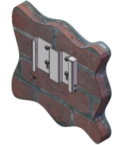
Slide the mating Mounting Bracket (attached to the Unit) into the Mounting Bracket Base until the locking clip engages, and install the provided 8-18 x .500” SS Thread Forming Torx Button Head Security Screw in the hole on the left side of the Bracket assembly.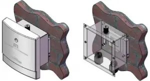
Mounting OrientationThe 7400-5902 Multiverse Vero Transceiver must be mounted exclusively in an upright mounting position with the cable entries on the bottom and antenna connector on the top as shown in the drawing above.
Pipe MountingThe Multiverse Vero Transceiver can also be mounted on a pipe. Attach the Mounting Bracket Base to a pipe using a stainless steel hose clamp (not included) as shown:
Slide the mating Mounting Bracket (attached to the Unit) into the Mounting Bracket Base until the locking clip engages, and install the retaining Screw.
Cable or Conduit EntryThe unit enclosure is provided with ½” NPT entry holes fitted with liquid-tight cable grips for use with outdoor use cables (by installer) for power and DMX connection. The recommended torque for these cable grips is as follows:
|
Locking Nut |
40-45 inch pounds |
|
Sealing Nut |
50-55 inch pounds |
f outdoor use conduit is used instead, it is recommended that the conduit be sealed after installation to prevent moisture entry, including free air exchange, in order to minimize the chance of condensation buildup.
Face Panel
Mains Wire Installation and TerminationInstall the mains cable or conduit in the entry provided as shown in Figure 2 on page 7. A liquid tight cable grip is provided for use with suitable outdoor rated cable with diameter range of .170”/4.3mm – .450”/11.4mmWhen cable is used, strip outer jacket 6”/150mm.
The mains connection is a 3 pos. plug/socket type terminal block which may be disconnected for ease of assembly. Strip insulation from individual conductors .25”/7mm and terminate in the provided screw terminal socket. Mains terminations are are marked on the unit
DMX512 WiringThe Multiverse Vero Transceiver is provided with a PCBA mount terminal block for DMX connection (see illustration above). DMX Input / Output connections are marked on the unit.
Installing the CoverThe Multiverse Vero Transceiver has a two part cover, with the outer plastic cover connected to the inner metal cover with a hinge. Install the metal inner cover using the eight provided 6-32 x .375” SS Truss Head Machine Screws. Hand install these screws until the screw threads are fully engaged with the mating PEM Nut, then tighten to 4 inch pounds.
The outer cover is then closed and secured with the provided 8-18 x .500” SS Thread Forming Torx Button Head Security Screw, installed in the provided hole on the left side of the cover assembly.
User Interface Screen
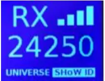
Upon power up, the Multiverse Vero Transceiver 900MHz/2.4GHz will boot into the main screen, which displays the SHoW ID and connection status. Pressing the “Up” or “Down” button will take you to the universe selection screen. Pressing “Enter” will select SHoW ID or universe for editing and will commit the change when done SHoW ID on Tx screen
 SHoW ID on Rx screen
 Universe on Rx screen
Pressing the “Menu” button will take you to the Menu screen. Holding the Menu button will cancel the current edit. See page 11 for a full description of menu selections. Transmitter menu screen
 Receiver menu screen
About SHoW IDChoosing and setting a SHoW ID is an important part of the Multiverse system. SHoW ID is a number that describes the portion of the spectrum on which the broadcast will take place (such as 2.4GHz or 900MHz), the area of that band where the broadcast will be directed (such as full band, low portion of the band only, high portion of the band only, etc.), and several other factors that influence the broadcast. Those factors are combined into a number called the SHoW ID. See the SHoW ID chart on page 10 for a full explanation.
Using A Spectrum Analyzer To Choose A SHoW IDIt is a good practice to utilize a device such as City Theatrical’s PN5988 RadioScan™ Spectrum Analyzer to analyze the spectrum in the area of the broadcast. RadioScan is a 900MHz and 2.4GHz spectrum analyzer, utilizing a hardware dongle and accompanying software, that enables you to easily visualize radio energy that is otherwise invisible to you. Using RadioScan helps you create a broadcast plan that optimizes the available spectrum in your area, and helps prevent interference with other mission critical radio devices near you
Radio Scan will guide you in creating the optimum broadcast plan for your installation by helping choose the best SHoW ID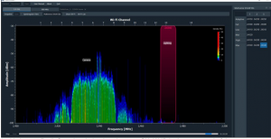 In this image, Radio Scan has helped to choose a SHoW ID in the upper end of the spectrum.If you do not have Radio Scan, devices like smartphones often have simple Wi-Fi visualizers which can help guide you to a more open area of the 2.4GHz spectrum.
Choosing a SHoW IDIn a single universe system with a Multiverse Vero Transceiver used as a transmitter and one or more Multiverse Vero Transceivers used as receivers, simply choose a SHoW ID and enter that SHoW ID into the user interface of the transmitter and all receivers. The universe number must match on transmitter and all receivers.
Here is a closer look at the SHoW ID numbering system:
Multiverse SHoW ID Example: 24302
Prefix9 900MHz Multiverse
Data RateFaster data rates provide more DMX universes. Slower data rates travel longer distances and provide more immunity to interference.
|
900MHz |
Universes |
Range |
| 1 | 1 | 2000’ Outdoor300’ Indoor |
| 2 | 2 | 2000’ Outdoor300’ Indoor |
| 3 | 4 | 500’ Outdoor300’ Indoor |
| 2.4GHz: | Universes | Range |
| 1 | 1 | 1500’ Outdoor300’ Indoor |
| 2 | 2 | 1500’ Outdoor300’ Indoor |
| 3 | 5 | 1000’ Outdoor100’ Indoor |
BandSpecifies which sections of the wireless band the frequency hopping utilizes.
- Use full range of 900MHz or 2.4GHz band.
- Use only low band channels.
- Use only mid band channels (available for Data Rate 1 only).
- Use only high band channels.
- Use only extreme high band to avoid WiFi (2.4GHz only.
- Adaptive hopping. Avoids busy channels by analyzing spectrum.
Hop PatternIf multiple wireless systems need to operate with the same data rate and band this value will change the hopping pattern to minimize overlapping between the two systems. Can be any number from 0 – 9 (not all bands have all Hop Patterns).
UniverseMultiple universe systems can be created by adding additional Multiverse Vero units as single universe transmitters. Separate universe numbers must be used for each additional group of transmitters and receivers. Any Multiverse Vero acting as a receiver that is set on a universe that Is not being broadcast by a Multiverse Vero acting as a transmitter will show its universe in a yellow color.
User Interface IconsAt the top of the main screen are several icons that indicate Multiverse Vero Transceiver 900MHz/2.4GHz status. These include:
- “TX” or “RX”The Multiverse Vero Transceiver is designated as either a transmitter or receiver on the Menu Screen (see below for instructions). Each unit will display either “TX” (transmitter) or “RX” (receiver) depending on which mode has been selected. The “TX” or “RX” symbol remains solid when DMX data is detected, and blinks if no DMX data is being received.
- Universe/SHoW IDThe display of the SHoW ID and the universe can be toggled back and forth by using the “up” and “down” buttons. Pressing “Enter” will select SHoW ID or universe for editing and will commit the change when done.
- Signal Quality BarsThe signal quality bars give a visualization of signal quality as seen at the receiver. The bars are not present when the unit is a transmitter. Four bars is excellent signal quality, three bars is good signal quality, two bars is fair, and one bar is marginal.
- Restore Factory DefaultsFactory defaults can be restored by holding the “Menu” and “Enter” buttons while on the main screen. Screen will flicker to signal when default process is complete. Default settings are listed below.
Menu ScreenPressing the “Menu” button takes you to the Menu screen. The Menu Screen displays different information depending on whether “Mode” is selected as “Receiver” or “Transmitter”.
In “Receiver” mode (the default mode), the choices are
- ModeSelect receiver mode or transmitter mode. Default is receiver.
- PowerOutput power may be user selected as Low, Med, Hi, or Maximum. It is a best practice to use the least amount of output power to achieve a successful broadcast. This helps to reduce reflections which can reduce signal fidelity, and to reduce any potential negative effect on other radio users in the area. You can monitor signal quality via RDM. Default is Maximum.
- AntennaIf a panel (P/N 5981) or Yagi (P/N 5982) antenna is used instead of the default omni antenna, choose it on this menu for optimum performance and to remain in compliance with FCC and other radio regulations. A PN5639 Gender Changer N(m) to N(m) is required to use a panel or Yagi antenna. Page 12 of 15
- SHoW Key (Multiverse SHoW IDs only)The optional SHoW Key setting allows a user to enter a key to privatize their SHoW ID from another system on the same SHoW ID. SHoW IDs and SHoW Keys need to match in order for receivers and transmitters to talk to each other. Keeping your SHoW Key private will provide a level of security to your Multiverse system from unauthorized use. It is not recommended to use different SHoW Keys in a system that uses multiple Multiverse Veros as Transmitters on the same SHoW ID. The range is 0 (Default) to 500.
| Situation | Condition | OK | |
| Same SHoW Key |
with |
Different SHoW IDs | Not OK |
| Different SHoW Keys |
with |
Same SHoW IDs | OK |
| Different SHoW Keys |
with |
Different SHoW IDs |
- RDM TrafficThe RDM Traffic setting determines whether RDM data is passed downstream of the Multiverse Vero Transceiver. It does not affect whether the Multiverse Vero Transceiver is detectable by devices upstream. It is recommended that RDM be turned off before production situations as many DMX devices do not correctly handle RDM data and may exhibit flickering or other undesired behavior. Default is Off.
- Backlight TimeoutThe Backlight Timeout setting determines how long the LCD backlight will remain on after the last button press. The timeout can be set to “Off” (backlight will never timeout)or any interval from 10 seconds to 59 minutes 59 seconds. Default is 59 minutes 59 seconds. After a screen timeout, pushing any button will wake up the screen without changing the screen selection
- Backlight LevelControls Backlight brightness. Range is 1%-100%. Default is 100%.
- InformationThe Information screen shows the RDM UID, firmware versions present, connection status, and the number of devices (receivers and fixtures) downstream
In “Transmitter” mode, these additional choices are available:
- TerminationIf DMX “out” is utilized on the DMX terminal block, set this switch to “Off”. If DMX “out” is not utilized, set the switch to “On”.
- Error CorrectionHigh noise environments can affect wireless DMX performance. Enabling Error Correction adds additional information to the data packets to correct errors in slot data that would have otherwise been lost, restoring DMX delivery back to near perfect levels. The extra data reduces the number of slots that can be transported, Max reduces slots by 50%, Med by 33%, Min by 25%. Only needs to be set at the Transmitter. Default is Off.
- mDMXImproves fidelity while dramatically reducing radio energy broadcast into the spectrum. Only needs to be set at the Transmitter. Default is On.
RDM SettingsThe Multiverse Vero Transceiver can be configured with a compatible RDM controller, such as DMXcat®. All of the settings available through the menu can be set via RDM. Aside from settings, you can also view the Device Model, Manufacturer, Firmware Versions, RDM UID, RF Signal Quality, and quantity of active Tx slots. You can also give each device a unique RDM Device Label to help with identification for configuration and troubleshooting.
Updating FirmwareFirmware updates and instructions for performing them are available on the product pages of the City Theatrical website
What’s Included
|
Label in Figure |
Item Description |
Part Number |
| 1 | Multiverse Vero Transceiver 900MHz/2.4GHz | 7400-5902 |
| 2 | Multiverse Vero Transceiver900MHz/2.4GHz | 5983 |
Specification
| Product Information | |
| Product Name | Multiverse Vero Transceiver (900MHz/2.4GHz) |
| Part Number | 7400-5902 |
| Maximum Concurrent Universes | 1 per transmitter |
| Frequency Range: | 2400 – 2480 MHz |
| 902 – 928 MHz | |
| Physical Specifications | |
| Height | 165.0mm (6.5 in) |
| Width | 152.0mm (6.0 in) |
| Depth | 102.0mm (4.0 in) |
| Weight | 0.77kg (1.70 lbs) |
| Antenna | Dual band 900MHz/2.4GHz 2.5dBi/2.5dBi |
| User Interface | Internal Backlit four button LCD display |
| Construction | NEMA 4 / IP66 Aluminum enclosure |
| EPA | 0.3125ft2 |
| Electrical | |
| Power | 90-277VAC input, 1A max, on 3 pin screw terminals |
| DMX Terminals | DMX In and Out via 3 pin screw termnals |
| Operating Temperature | -25ºC-60ºC |
| Radio Technology | |
| Latency | 4 ms average |
| RF Sensitivity | -95dBm |
| Loss of Data Behavior | Output stops |
| Broadcast Power | 3.2mW, 10mW, 32mW, 100mW EIRP |
| Broadcast Modes | Adaptive, Full, Low, Mid, High, Max |
| Show IDs | Multiverse: 307; Neo: 70 |
| RDM Features | RDM Proxy, RDM Responder |
| Product Information | |
| Use Environment | Indoor or Outdoor |
| IP Rating | IP66 |
| Compliance | FCC, IC, cETLus Listed |
| Warranty | One year |
Troubleshooting
Table 5: Troubleshooting Guide
| Symptom | Solution(s) |
| Unit does not power up. | Check that power input wiring is properly installed. |
| Test power outlet with another device. | |
|
Fixtures connected to the receiver are not responding. |
Check that the Tx and Rx symbols on transmitters and receivers are solid. |
| Check that SHoW ID and SHoW Key (and optional SHoW Key) match on transmitters and receivers. | |
| Check that universe setting matches on Tx and Rx. |
Table 6: Legacy SHoW IDs Guide
| SHoW DMX Neo SHoW ID | Broadcast Location |
| 201 | Adaptive hopping |
| 102 | Full bandwidth hopping |
| 117 | Low band hopping |
| 133 | Mid band hopping |
| 149 | High band hopping |
| 165 | Max band hopping |
[xyz-ips snippet=”download-snippet”]