
BM89 Operating Instruction
Introduction
Welcome to use this product.
BM89 is a kind of portable clamp meter, it can be used to measure DC voltage and current, AC voltage and current,TRUE RMS, resistance, frequency, continuity, temperature, the forward voltage drop of diode .capcitance measurement range extended to 10mF, more fast to measure large capacitance. This product is an excellent tool for electricity measurement with its compact structure, easy to be operated ,convinent to be carried, especially suitable for the measurement of refrigeration equipment, electrical repair and large current situations,the inrush current test function is especially suitablefor the measurement of starting current.
Safety standard
The meter in structure complies with the safety requirements of ICE61010-1. Read the instruction carefully as follows before you use the meter:
- When measuring voltage, AC or DC voltage should not be more than the peak voltage (DC500V / AC 500V) of the meter.
- Voltage of less than 36V is safety voltage. When the voltage is more than DC 36V or AC 25V, the leads should be checked. The test lead should be connected correctly and their insulating property should be under excellent status against electric shock.
- When change of functional measuring range, the test lead should be away from test point.
- It is suggested that for safety the functions and range should be selected correctly although protective function for the full measuring range exists.
- When measurement of current, the input current shouldn’t be more than the maximum current labeled on input end.
- Safety symbols:


Features
General
- The meter is based on CMOS large scale IC and can automatically changed measuring range for measurement of AC/DC voltage, AC current, resistance, frequency and capacity, which makes the meter easy to be used.
- Display mode: Display by LCD.
- Maximum display: 3999 or 9999(when measuring capacitance and frequency)
- Maximum span of jaw: 32mm.
- Data Hold:Short time pressing”DH” key can maintain the current readings, release the button to cancel data hold function. In ACvoltage and current measurement function,press the key for more than 2 seconds ,the INR measurement of inrush voltage and current will be displayed.
- Auto negative polarity indication: Displaying “-”.
- Lack of battery power: Displaying “Battery”.
- Auto power OFFAfter turning on the instrument and without operating the function switch or pressing any button, the instrument will automatically enter into sleep mode after 10 minutes,to save battery power.when it is in the sleep mode you can press the SELECT key to wake up the instrument. If you don’t need the automatic sleep mode, you should hold down the DH key to turn on the instrument, and then the symbol” ” will not be display on the LCD.
- Work environment: 0C-40C, ≤75%RH.
- Storage environment: -10C-60C, ≤85%RH.
- Battery: 3V (AAA1.5V×2)
- External dimensions: 169(L)×62(W)×28(H)mm
- Weight: About 180g (including battery’s weight)
Technical specifications
Accuracy:±(% reading + digit); calibration term is one year.Ambient temperature: 23C±5C;Ambient humidity: ≤70%RH
DCV
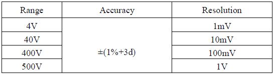
Input impendance:about10MΩ
ACV
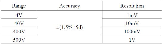
Input impendance : about 10MΩFrequency : 10Hz~1kHz (Warning : Frequency for square wave accuracy is specified from 10Hz to 400Hz), display : TRUE RMS(sinusoidal waveform RMS calibration).
ACA
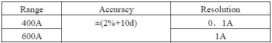
AC Conversion Type: TRUE RMS responding, calibrated readings consistent with sinusoidal waveform RMS. FrequencyRange:50~60Hz。
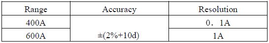
DCA
Resistance Ω

Overload Protection:effective value 220V
Capacitance
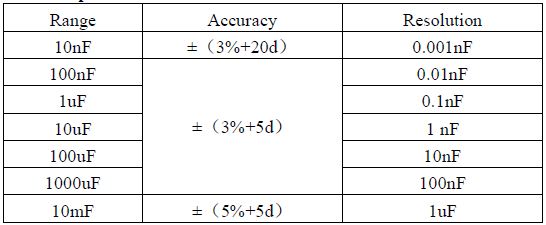
Overload protection: effective value 250Vwarning:There is about 20pF dead zone in the 10nF,capacitance below 20pF can not be measured
Frequency
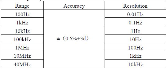
Overload protection: effective value 250V. Input sensitivity RMS: 2V.
NOTE: If the voltage of the frequency being measured is above 30V, set the switch to the ACV measured function and press “SELECT” key to enter voltage frequency measurement function, in order to avoid demage the instrument.
Temperature
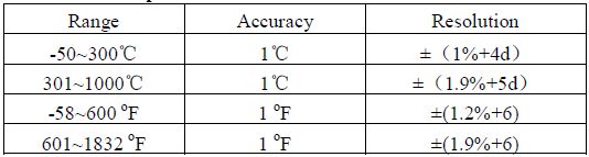
Temperature sensor: K WRNM- 010 bare contact thermojunctionOverload protection:effective value 250V.
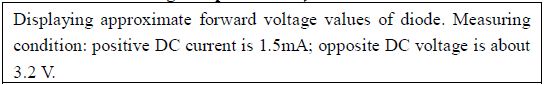
Forward voltage drop of diode
Continuity Test
Operation
Instruction for control panel
- When the push switch is in the middle position,it is in OFF gear
- push forward:This position is used to measure AC and DC current, ACV, DCV, Voltage frequency and DUTY Ratio, press “SELECT” to change function you need in turn .In the voltage and current measurement function press “RANGE” key to choose the manual range function. In the voltage frequency measurement functionpress “RANGE” key to select the DUTY Ratio or frequency measurement. DH is a data hold button, in AC measurement function, press the button 2 seconds to enter in rush measurement function. Press 2 seconds again it will turn back to normalmeasurement. In the DC current measurement function press DH key 2 seconds can make the instrument back to zero.
- push backward: This position is used to measure resistance, diode, continuity, capacitance, frequency, temperature. press”SELECT” key to change function you need in turn, in the resistance measuring function press “RANGE”key to select the manual range function. When it is in temperature measurement function, press the “RANGE” key to select ℃ or °F.
- “V”jack: This is positive input terminal for voltage, resistance frequency, temperature, capacity and diode.
- “COM”jack: This is negative (ground) input terminal
Measurement of AC/DC voltage
- Set the push switch to “V”. This instrument is preset to the current range, press ”SELECT” key to select voltage measurement function,Then plug black lead in “COM” socket, and plug red lead in “V/” socket. connect the test lead with the two ends of the circuit and then directly read the reading on the LCD display
- INR is to measure inrush voltage:in AC voltage measurement function,press “DH”for 2seconds it will enter inrush measurement and display”INR”the minimum period of the effective inrush voltage it can measure is 80mS .In the inrush measuring funciton ,range can only be change manually, before the test,if the voltage is unknown, press “RANGE”key to set the measuring range to the maximun and then enter the INRUSH measuring function,press the same key to cancel surge measurement function,”INR”simble dispeared.
- When the instrument is measuring DC or AC voltage, if the value is more than 550V, the screen only displays OL for the tested voltage is higher than the instrument can measure.
Measurement of DC/AC current
DC current measurement
Turn the switch to“A”range, This instrument is preset to the DC current range,
- Press the trigger, opens the mouth of the clamp, and hold a wire ( put the wire in the clamp center ),get the reading directly.
- if the display does not return to zero after used, press “DH/ZERO”more than 2 seconds it will return to zero.
AC current measurement
Turn the switch to“A” position. press “SELECT” key to choose AC current .Press the trigger, opens the mouth of the clamp, and hold wire ( put the wire in the clamp center ), get the reading directly
When measuring AC current, press DH 2 seconds to enter INRUSH measuring function, “INR” simble will be display on the screen. This function can measure the minimum period of inrush current 80mS RMS, when enter the surge mode, the instrument automatically set the manual range,if the measurement value is unknowed,please pressRANGE key to select to the maximum range and then enter the surge measurements. Then press the same key for 2 seconds and then cancel surge measurement function, “INR” signs disappeared.
Measurement of resistance, continuity, capacitance and forward Voltage drop of diode.
- push the switch to the range of Ω. At this time, the meter is reserved at resistance range.
- Plug red lead in “V/Ω” socket, and plug black lead in “COM” socket
- Connect the leads with the two ends of the circuit or component, and then read the value of resistance.
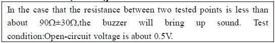
- Press SELECT key to change the range of Continuity. When the resistance measured is less than about 90±30, the buzzer sounds. This is continuity testing.
- When the test lead is under open-circuit or input-overload status, the LCD will display “OL”.
- When measuring diode,press the “SELECT” key to the function of Diode.
- Connect the test lead with the two ends of the diode, and then read the value of forward voltage drop.
- When the test lead is under reverse connection to the diode or open-circuit status, the display will display “OL”.
- When measuring capacitance, press “SELECT” key to the function of, this mode can not be set range manually, when the capacitance is too large, it will take several seconds for the measurement.
Measurement of frequency / DUTY ratio
- Push the switch to “Hz” function, press “SELECT” to choose frequency measuring function,.if you want to measure DUTY Ratio,press “RANGE” key to switch
- Plug red test lead in “V/Ω” terminal and plug black lead in “COM” terminal.
- Connect the test lead with measured circuit and then get the reading.
- when the voltage exceeding 30V, please enter the voltage frequency measurement mode by pressing the “SELECT” key in the “ACV” measurement function.if you want to measure DUTY ratio, press “RANGE” to switch.
Caution: voltage frequency measurement range is 10Hz~40kHz, it is suitable for the frequency that voltage more than 30V, low voltage output signal may not be measured, the normal frequency measurement function should not measure the frequency more than 30V.
Measurement of temperature
Push the switch to the “℃”function of temperature, then plug the cold end (plug end) of temperature sensor to the V/Ωand COM socket(black end for COM socket and red end for V/Ω socket). Place the working end (the temperature measuringt end) of the sensor on or in the measured object. Then read the temperature value (in ℃) on the display.If you need to measure that “OF”, press the “RANGE” key to switch.
Caution: When the cold terminal of the sensor isn’t inserted into the meter, the meter might display approximate environmental temperature. K WRNM- 010 bare contact thermojunction has a limiting temperature of 250℃ (300℃ for short time).
Maintenance of meter
Warning! Switch off the power, remove the test lead and any of input signals to prevent electric shock before opening the cover of meter or the cover of battery.
- When the meter displays the symbol of “Battery”, the battery should be changed. Open the battery cover, and then change the used battery with new battery to ensure the normal operation of the meter.
- Keep the meter and the pens clean, dry and non-destructive. Clean cloth or detergent may be used for cleaning the cover of the meter. No grinding agent or organic solvent can be used for the same cleaning purpose.
- The meter should be protected against damage, vibration and impact. It shouldn’t be placed where high temperature or intense magnetic field exists.
- Calibrating of the meter is done on a yearly basis.
Accessories
- Test lead: 1 set
- users manual: 1 piece
- Temperature sensors: 1 set
High Precision Smart Clamp Meter Automatic Measurement Capacitance Frequency Temperature Clamp Multimeter BM89 Operating Instruction – High Precision Smart Clamp Meter Automatic Measurement Capacitance Frequency Temperature Clamp Multimeter BM89 Operating Instruction –
[xyz-ips snippet=”download-snippet”]