CLIPSAL 360° Infrascan passive infrared motion sensor
Safety Information
The Infrascan units are mains-connected devices. They are designed for indoor use in residences and businesses. The products must be installed by qualified and licensed personnel. There are no user serviceable parts inside the units.A ‘WARNING’ in this document alerts you to a hazard that, if ignored, could cause serious injury or a dangerous condition and also tells you how to prevent problems. A ‘Caution’ warns you that certain actions could cause damage to the equipment or nearby property. Note that damage to the equipment might not be immediately detected.
WARNING: Connected Loads Can Turn On and Off Unexpectedly.This product controls motors and lighting fixtures that can turn on or off unexpectedly which could cause serious injury. Always remove power from connected devices before performing maintenance. Use this product only as described in the instructions. Do not modify or use the product for any other purpose. Never open the outer casing, refer all repairs and damaged units to your local Schneider Electric representative.
WARNING: Electrical Shock and Arcing HazardDangerous voltages are present inside the unit. Always refer installation and servicing to a qualified expert and do not disassemble the unit. Failure to follow these instructions could cause death, serious personal injury or fire. Dangerous voltages are present inside the unit. Always refer installation and servicing to a qualified expert and do not disassemble the unit. Failure to follow these instructions could cause death, serious personal injury or fire.
Technical Support
For further assistance in using this product, consult your nearest Schneider Electric or Clipsal by Schneider Electric Sales Representative or Technical Support Officer. Technical Support email: [email protected] Schneider Electric (Australia) Pty Ltd reserves the right to change specifications, modify designs and discontinue items without incurring obligation and whilst every effort is made to ensure that descriptions, specifications and other information in this catalogue are correct, no warranty is given in respect thereof and the company shall not be liable for any error therein. Clipsal is a registered trademark of Schneider Electric. Infrascan is a trademark of Schneider Electric. All other trademarks are the property of their respective owners.
Product Range
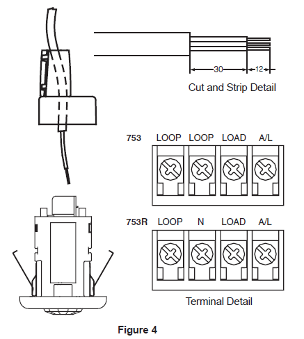
753 Infrascan 360 Degree, 240V a.c., 50Hz,2-Wire, 2A, 5 sec – 20 min timer753R Infrascan 360 Degree, 240V a.c., 50Hz,3-Wire, 10A, 5 sec – 20 min timer
Product Selection
The 753 is a 2-wire (does not require Neutral connection), and can only switch a limited range of load types. The 753R is a 3-wire device (requires Neutral connection to operate) capable of switching a wide range of load types
| Catalogue Number | Neutral Required | Maximum Load* |
| 753 | NO | 2A |
| 753R | YES | 10A |
Description
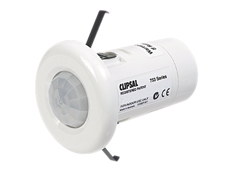
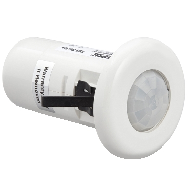
The Clipsal 753 Series 360 Degree Infrascan is a highly reliable, state-of-the-art passive infrared (PIR) occupancy sensor. The unit utilises an advanced quadelement sensor array allowing instantaneous detection of movement and features a10-metre detection range. The unit also features a slimline, fully-recessed mounting facility. The unit is designed to monitor the immediate environment, and detect people moving within its field of view. When movement is detected, the unit will activate an electrical load, such as a light, in response to that movement. Designed and developed in Australia, the unit offers benefits in security, energymanagement, hospitality and true ‘hands-free’ switching convenience in a wide range of applications.
How it Works
When power is applied and a suitable load connected, the Infrascan can detect any moving infrared source (for example a person) within its field of view. Light-Level and Time-On settings are user-adjustable and accessible by removingthe front surround. Simply twist to remove the cover and adjust the dials as required. The Light-Level adjustment activates the load, dependent on the ambient light level in the field of view of the sensor. This adjustment can be set to allow the Infrascanto operate the load at any light level between full daylight and almost complete darkness. For example, the user can ensure the load is only activated when movement is detected at night time. During the day time, when there is adequate natural light, the unit can be set so it does not activate the load. The Time-On adjustment varies the time span that the load will remain on afterthe infrared source moves out of, or stops moving within the field of view. Theload will automatically be switched off after the Time-On period has elapsed. Any period between 5 seconds and approximately 20 minutes may be set by the time adjustment screw. The sensor head is specially designed to give optimum performance and is sealed to prevent water or dust from entering the unit. Under no circumstances should it be tampered with. Do not apply any pressure on the actual sensor lens itself, as this may damage the lens, and adversely affect the performance of the unit.
Identification of Parts
5.1 Zone Mask (753MASK)The unit is supplied with an optional zone mask, designed to block the unit from detecting motion in unwanted trip areas. This might include a smaller office space with an open doorway, where it is not desirable to activate lighting when peoplepass by the open door. The zone mask incorporates a series of staged tear-away sections, allowing full customisation of the field of view. Tear away sections where you want detection to take place. To fit the zone mask, remove the surround and unclip the removable spacer. Clip the zone mask in place and replace the surround. Additional zone masks are available (Clipsal Catalogue Number 753MASK).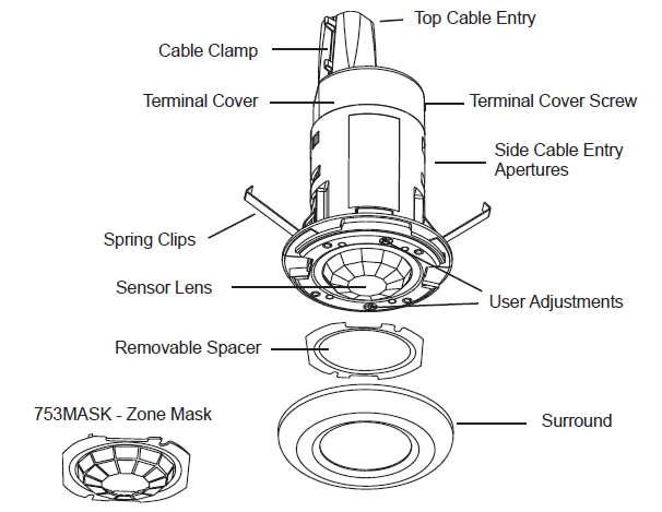
Installation Location
An Infrascan must be positioned correctly to ensure effective operation. The field of view is optimum when the sensor head is mounted in a vertical position at a height of 2.4 meters and the approach path is across the face of the sensor.
- Do not mount the Infrascan close to objects which can create rapid temperature changes, e.g. air conditioning vents, heater flues, moving water (i.e. fountains and sprinklers). Avoid locations where condensation is likely to form on the lens.
- Do not mount the Infrascan on any surface that is subject to movement due to wind or other causes.
- In all cases, locate the Infrascan so that the approach path is across the field of view and not directly towards the Infrascan, as a reduced detection range will be observed.
Field of View
The stated field of view is typical for full body movement and is subject to variations caused by the type and quantity of clothing worn, as well as variable background temperature characteristics and speed of movement. Rapid and large temperature changes may be detected even if they appear to be well beyond the field of view due to reflection off surfaces that are within the field of view.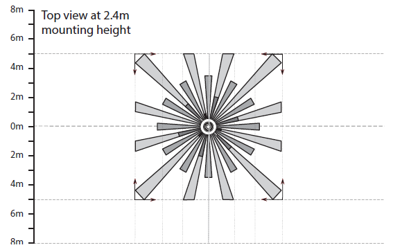
Mounting Procedure
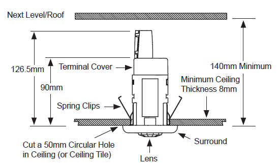
Use the Figures and the numbered steps to install the unit.Use TOP CABLE ENTRY only for attaching cables. Do not use SIDE ENTRY. When mounting in suspended ceilings there should be at least 140mm between the lower surface of the tile and the hard surface above. Do not apply any pressure on the actual sensor lens itself as this may damage the lens. Take care not to scratch or damage the translucent window on the front of the Infrascan, as it forms part of the optical detection system. For continued optimum performance ensure that the window is cleaned periodically with mild soap, water and a soft cloth.
- Using a hole saw or otherwise, cut a 50mm (2”) circular hole in the ceiling(or ceiling tile). Draw cable through hole.
- Remove terminal cover screw and terminal cover to expose terminals.Remove cable entry tear-away(s) from the terminal cover as required, to suitincoming cable.
- Use TOP CABLE ENTRY. Punch out the top cable entry hole, then fit the cable clamp to the terminal cover. Push the two halves so that it snaps together, and clip onto the terminal cover entry hole. The cable clamp wraps around the incoming cable. Feed cable through. DO NOT USE SIDE ENTRY.
- Strip cable. Terminate incoming wiring on the appropriate terminals as marked. Refer to Sections 9 and 10, Wiring Diagrams, for further information about wiring for different applications.
- Fit the terminal cover, and secure using the terminal cover screw.
- Press the outer ends of the spring clips towards the centre of the unit and push the unit through the hole until it rests flat on the ceiling
 Important Notice
- It is illegal for persons other than licensed electricians or persons authorised by legislation to work on fixed wiring of any electrical installation. Penalties for conviction are severe.
- Installation must be carried out in accordance with local wiring rules (AS/ NZS3000 Australia and New Zealand).
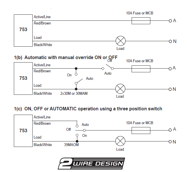
Wiring Diagrams for the 753 2-Wire Infrascan
Notes:
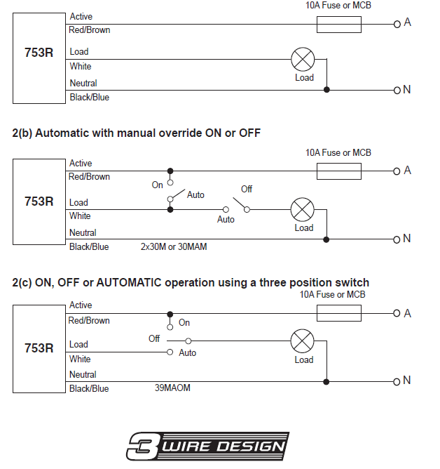
- When switching to AUTO for any of the above configurations the Infrascan will turn on. Allow 30 seconds plus Time-On period for the sensor to stabilise for normal operation. Wiring diagram 1(a), without override switches is preferred asthere is no settling period.
- More than one 753 CANNOT be connected in parallel to a common load. If parallel connection of multiple devices to control a common load is required, use Cat. No. 753R.
Wiring Diagrams for the 753R 3-Wire InfrascanCommissioning
 Commissioning
When setting the Time-On or Light-Level adjustments keep clear of the field of view when assessing the effect of the adjustment. 11.1 Setting Up for the Walk Test
| 1 | Connect unit to mains power and allow at least 30 seconds for the unit to
stabilise before conducting any tests. |
| 2 | Twist and remove the front surround and use a screwdriver to set the
‘Time-On’ adjustment fully anti-clockwise (5 second timer set). |
| 3 | Set the ‘Light-Level‘ sensor adjustment fully anti-clockwise (unit set to
respond in light or dark conditions). |
|
4 |
Walk slowly around the area in the desired field of view to confirm the load is
activated from within the desired area. Check that the unit responds appropriately when entering the room.Check that the unit does not trigger unnecessarily when walking past open entry ways (e.g. adjoining hallway or corridor). Fit the zone mask if necessary to restrict the field of view to avoid nuisance tripping. |
| 5 | Set the ‘Light-Level’ as desired for activation at dusk for normal operation. |
| 6 | Set the ‘Time-On’ interval to the desired time for normal operation. |
| 7 | Replace the front surround. |

Troubleshooting
| Problem | Possible Cause | Possible Action |
| Light turns on for no apparent reason. | Momentary power failure. | None, unit will reset after Time-Out. |
| Unseen target. | Check for animals, e.g. dogs/ cats, etc. | |
| Extreme draughts of hot and cold air. | Check doors, windows or air conditioning outlets. | |
| Trees/bushes moving in the wind. | Re-aim sensor head. | |
| Vehicular or pedestrian traffic on edge of field of view. | Re-aim sensor head. | |
| Light turns on during daylight. | Wrong setting on Light Adjustment. | Reset according to Commissioning Instructions. |
| Lights do not turn on in dim and dark conditions. | Wrong setting on Light Adjustment. | Reset according to Commissioning Instructions. |
| Light globe blown. | Replace light globe. | |
| Light remains permanently on. | Manual override switch fitted
and set to Manual. |
Reset according to Commissioning Instructions. |
| Moving infrared source being detected.
Note: do not mount too close to objects which can change temperature rapidly, e.g. air conditioner vents, heater flues, moving water (i.e. fountains, sprinklers). |
Remove unwanted infrared source. If unable to resolve, blank off viewing window. Light should turn off after Time-Out. If light still remains on, call installer. |
Note:Take care not to scratch or damage the translucent window on the front of the Infrascan, as it forms part of the optical detection system. For continued optimum performance ensure that the window is cleaned periodically with mild soap, water and a soft cloth.
Technical Specifications
| Catalogue Number | 753 | 753R |
| Operating Voltage | 200 – 265 Va.c., 50Hz | |
| Maximum Load Current | 2 A | 10 A |
| Minimum Load (Watts)* | 40 W | 0 W |
| Maximum Off-State Leakage Current | 10 mA | 0 mA |
| Stand-By Power Consumption | < 1W | < 1W |
| Conductors Required | 2-WIRE | 3-WIRE |
| Neutral Required | NO | YES |
| Operating Temperature Range | 0° – 50°C | |
| Warm-Up Time | 30 seconds | |
| Rated Detection Field at Max Sensitivity** | 360°, circular detection field,10 m diameter | |
| Optimal Mounting Height for Rated Detection Field |
2.4 metres |
|
| Timer Delay Range | 5 seconds to 20 minutes, user adjustable*** | |
|
Light Level Inhibit Threshold |
Continuous from 1 lux to full sunlight, user adjustable | |
| Mounting Surface | Ceiling mount | |
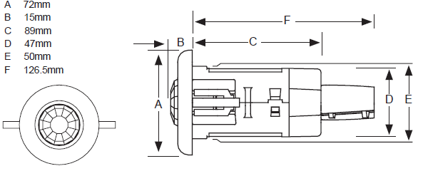
| Overall Dimensions | 72mm diameter x 141.5mm high | |
| Cut-Out Dimension | 50mm holesaw | |
|
Cables Accommodated |
4 terminals, up to 2 x 2.5mm2 cable per terminal |
| Catalogue Number | 753 | 753R |
| Compatible Load Types | Incandescent 240V Halogen
Iron Core Transformers**** |
Incandescent 240V Halogen
Fluorescent
Iron Core Transformers Electronic Transformers M Small Motor Loads 5A – Shaded Pole Induction Motors 5A Max (exhaust fans) – Split Phase Induction Motors 5A Max (ceiling fans) |
| Incompatible Load Types | Electronic Transformers
Fluorescent Loads Discharge Lamps M Motor Loads |
N/A |
| Specifications Typical @ 240V a.c., 25°C | ||
| No user serviceable parts inside. | ||
| This product is recommended for INDOOR USE ONLY. |
- The 753 2-Wire Infrascan must be connected to a minimum 40W load, unless the 31CAP (sold separately) is fitted. Failure to do so may cause unexpected or erratic switching of the load.
- The range specifications given are based on a 90kg person travelling at greater than 1 metre per second across the field of view, where there is a temperature differential greater than 5° Celsius between the person and the background. Objects that are hotter or moving faster (e.g. motor vehicle on nearby roadway) may be detected at greater distances. A person covered in heavy clothing or walking directly towards the sensor may not be detected until they get much closer to the unit.
- Other models are available with longer Time-Out ranges, designated 753Rxx (where xx is the Time-Out period in minutes). Only iron-core transformers compatible with electronic switches may be used to ensurecompliance with IEC 60669-2-1.
Warning: Using the 753 with Special Loads Small Loads (<40W)
The 753 product can only drive loads greater than 40W. If you wish to drive a smaller load, the 31CAP Load Correction Device is required to be fitted in parallel with the load. For example: when driving a single contactor, be sure to use the31CAP. Loads which are Sensitive to Leakage Currents The 753 is a two-wire device. Two-wire devices draw their power through the load. If this device is used in conjunction with a load, which cannot provide enough continuous load current in the off-state, or the load is sensitive to a high offstate leakage current (for example: relays, contactors, various loads with built-in electronic control, etc.) a 31CAP Load Correction Device must be connected in parallel with the load.Small (Non-Power Factor Corrected) Fluorescent Loads When a 31CAP is fitted, some small non-power factor corrected fluorescent loads may be controlled using the 753. Success varies from manufacturer tomanufacturer. Recommend testing before installation. Installation must be compliant with local wiring rules.
Note: Please note the 753R is a three-wire device, and switches the load using an internal relay. Power is not drawn through the load and so the 31CAP is not required.
Warranty
- The benefits conferred herein are in addition to, and in no way shall be deemed to derogate; either expressly or by implication, any or all other rights and remedies in respect to the Clipsal product, which the consumer has under the Commonwealth Trade Practices Act or any other similar State or Territory Laws.
- The warrantor is Schneider Electric (Australia) Pty Ltd of 33-37 Port Wakefield Road, Gepps Cross, South Australia 5094. Telephone (08) 8161 0511. With registered offices in all Australian States.
- This Clipsal product is guaranteed against faulty workmanship and materials for a period of two (2) years from the date of installation.
- Schneider Electric (Australia) Pty Ltd reserves the right, at its discretion, to either repair free of parts and labour charges, replace or offer refund in respect to any article found to be faulty due to materials, parts or workmanship.
- This warranty is expressly subject to the Clipsal product being installed, wired, tested, operated and used in accordance with the manufacturer’s instructions.
- All costs of a claim shall be met by Schneider Electric (Australia) Pty Ltd, however should the product that is the subject of the claim be found to be in good working order all such costs shall be met by the claimant.
- When making a claim the consumer shall forward the Clipsal product to the nearest office of Schneider Electric (Australia) Pty Ltd with adequate particulars of the defect within 28 days of the fault occurring. The product should be returned securely packed, complete with details of the date and place of purchase, description of load, and circumstances of malfunction.
Schneider Electric (Australia) Pty LtdContact us: clipsal.com/feedbackNational Customer Care Enquiries:Tel 13 78 23![]()
[xyz-ips snippet=”download-snippet”]