
![]()
C-Bus
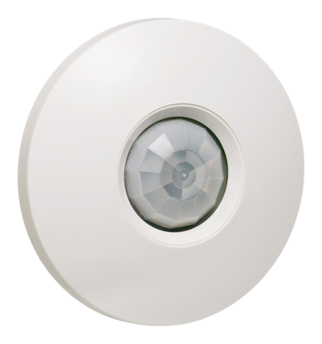
360° Occupancy/Light Level Detector,Surface Mount5754ODPE

Installation Instructions
C-Bus and Clipsal are registered trademarks of Schneider Electric.All other trademarks are the property of their respective owners.The information in this manual is provided in good faith. Schneider Electric has endeavored to ensure the relevance and accuracy of the information but assumes no responsibility for any loss incurred as a result of its use. Schneider Electric does not warrant that the information is fit for any particular purpose, nor does it endorse its use in applications that are critical to the health or life of any human being. Schneider Electric reserves the right to update the information at any time without notice.December 2011
Introduction
The 5754ODPE C-Bus 360° Occupancy/Light Level Detector, is a C-Bus input unit that detects any moving infrared source within its detection area. The detector uses passive infrared (PIR) technology to detect the movement of body heat within its range. The unit issues command over the C-Bus network to control output devices such as dimmers or relays. The TIME ON timer interval adjustment is set using C-Bus Toolkit software.The 5754ODPE includes an ambient light sensor that allows different behavior in dark and light conditions. The light level required to change from light to dark is adjustable and can be set at a level that ranges from full daylight to almost complete darkness. Remove the cover to adjust the trim pots.
Safety and Product Handling
The detector is for indoor use only with C-Bus systems. It is never connected to building power or an external power supply. Read and follow all instructions found on the product and its packaging.
WARNING Avoid Electrical Shock
DO NOT connect the unit to mains power or any telephony or Internet equipment. The detector is a Class 2, extra-low voltage (ELV) device. DO NOT connect the unit to an external power supply or a non-C-Bus network.Use caution when drilling holes in ceilings. Check for the presence of electrical wiring and water pipes before drilling.
Caution Sensitive Components Inside
Static discharge and rough handling can damage the components on the circuit board. Use antistatic procedures when handling the opened unit. Avoid touching the photosensor and other electronic components.Changes or modifications not expressly approved by Clipsal could void the user’s authority to operate the equipment (under FCC rules).
Caution Avoid Damage to the LensThe fresnel lens is easily scratched. Scratches on the lens will reduce the accuracy of the detector. Use care when installing and configuring the unit.
Installation
During installation be careful not to damage the lens or electronic parts on the circuit board. Rough handling or electrostatic discharge can damage the detector unit.
Selecting a Location
The detector is for indoor use only. Do not place the unit where it will be exposed to dripping water, steam or direct sunlight. The 5754ODPE is designed for surface mounting on the ceiling. The best location is in the center of the room. A typical room plan example is shown in Figure 1.
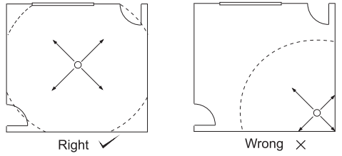 Figure 1. Placement of the detector in a roomThe location selected for the detector should be free from obstructions that will block the infrared detection pattern or cause an inaccurate light level reading. Do not locate the detector near a source of hot or cold air, such as an air conditioning vent. The detector has 360° degree detection coverage up to 10 meters when mounted 2.4 meters above the floor. Mounting the detector higher than 2.4m from the floor will have the effect of slightly increasing the detection area. Do not mount the detector more than 3.7m from the floor.
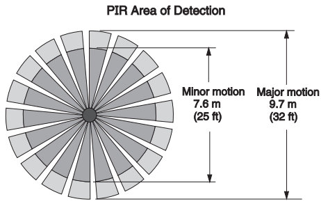 Figure 2. Typical detection area at 2.4m mounting height
Note: The sensitivity to motion is greatest when a person is walking across the detection area and is slightly less when a person is walking directly toward the detector from the border of the detection area.Disclaimer: The stated field of view is typical for full-body movement and is subject to variations caused by the type and quantity of clothing worn, as well as variable background temperature characteristics and speed of movement.
Removing the Top Cover
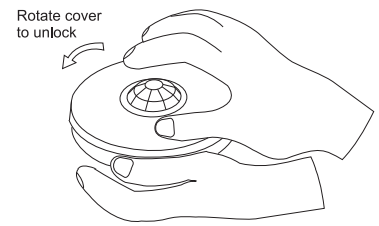
The detector housing consists of two pieces, the base, and the cover. No tools are required to remove the cover. To remove the top cover grasp the base with one hand and rotate the top anti-clockwise with your other hand. Refer to the illustration below:Note: Do not remove the lens from the top cover.
Installing the Mounting HardwareThe base of the detector is secured in two places (see Figure 4). Drill the holes for the screws or anchors and then follow instructions for mounting the detector.
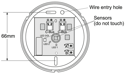 Figure 4. Mounting hole locations in the base
Mounting the DetectorPass the network cable through the wire entry hole and then attach the detector’s base to the ceiling using the two screws or anchors as described in Section 3.3. The network wiring to the detector must be supported properly.
Connecting the C-Bus Network WiringUse Cat 5e Unshielded Twisted Pair (UTP) C-Bus cable. The use of bootlace ferrules (crimps) for screw terminals is recommended for a reliable connection. C-Bus cable conductor assignments are provided in Table 1. The Clipsal catalog numbers for the C-Bus network cable is 5005C305B (solid conductors) and 5005C305BST (stranded conductors).
| Pin | C-Bus Connection | Colour |
| 1 | Remote ON | green & white |
| 2 | Remote ON | green |
| 3 | C-Bus Negative (–) | orange & white |
| 4 | C-Bus Positive (+) | blue |
| 5 | C-Bus Negative | blue & white |
| 6 | C-Bus Positive (+) | orange |
| 7 | Remote OFF | brown & white |
| 8 | Remote OFF | brown |
Table 1. C-Bus network cable conductor definitionsThe C-Bus network uses polarised twisted wire pairs. The detector has two removable screw-type connectors. Strip the insulation from the twisted pairs and then connect the C-Bus positive (+) and C-Bus negative (–) twisted pairs to the screw terminals as shown in Figure 5.
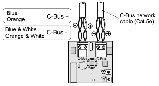 Figure 5. C-Bus wiring diagram
Push the terminal plugs onto the pins on the circuit board.It is recommended that you seal the entry hole area with silicon rubber to keep dust and debris out of the detector. Install the top cover by aligning the tabs on the slots and rotating the top cover in a clockwise direction.Note: The Remote On and Remote Off signals are not used on the detector, but you should maintain these signal connections throughout the network.
Controls and Indicators
There are two trimpots (potentiometers) located on the circuit board. You must remove the cover in order to set the trimpots. The C-Bus network must be connected and working in order to perform the setup using the trimpots.Trimpot A can be set at a level that ranges from full daylight to almost complete darkness. Remove the cover to adjust the trimpot. Adjusting the trimpot in a clockwise direction increases the light level setting.Trimpot B adjusts the sensitivity of the PIR detector. This allows you to set the distance at which movement will cause the detector to report occupancy and start the ‘timer on’ function. Full clockwise rotation provides the maximum detection coverage.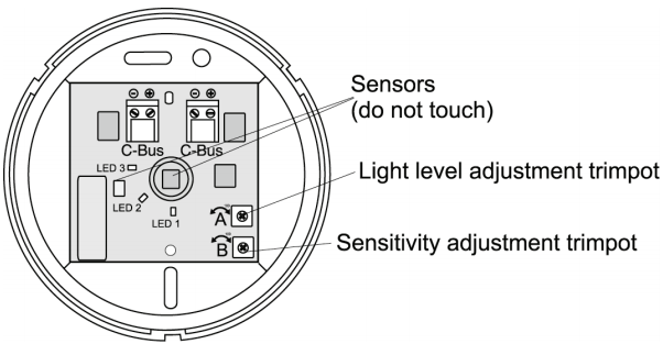 Figure 6. Location of trimpots on the circuit boardLED 1, Status of the Group. This orange LED is on when the assigned network group is active.LED 2, Light level maintenance active LED. This red LED is on when light level monitoring is active, so the unit will be actively monitoring the lighting level and controlling a group to keep the light level in the monitored area within Light Level Target+/- Light Level Threshold.LED 3, Occupancy detection active. This LED can be programmed to turn on when movement is detected. This LED can be turned off using the software.
Programming and Commissioning
The 5754ODPE must be programmed to set a unique identification (Unit Address) and mode of operation on the C-Bus network. This can be achieved using C-Bus Toolkit software or learn mode. The latest C-Bus Toolkit software may be downloaded from the Clipsal Integrated Systems website (www.clipsal.com/cis).The use of any non-C-Bus Software in conjunction with the hardware installation without the written consent of Clipsal Integrated Systems may void any warranties applicable to the hardware.Set the Target Level in Lux. The ambient light level in the work area of interest can be used to set the Target light level in the Toolkit GUI. This allows you to choose a target level based on personal preferences, or you can use a hand-held lux level meter for precise adjustment.
Walk Testing the Detection Area
| 1. | Connect the detector to the C-Bus Network and allow about two minutes for the unit to stabilize. Remove the top cover by rotating it in an anti-clockwise direction. |
| 2. | Turn Trimpot A to its maximum value, fully clockwise. Do not force the adjustment screw beyond its range of travel. This setting allows the detector to respond to ambient light depending on the current C-Bus Toolkit setting. The initial setting of POT B is not critical. You can increase or decrease as necessary based on your ‘walk test’ in the monitored area. |
| 3. | Install the cover. Using C-Bus Toolkit software, set the target light level to the selected value and set up the detector to control a load with the Sunset function. In this case, there is no need to set a timer. The load will turn on when the Light Level is less than Target -Threshold and it will turn off when the Light Level is greater than Target + Threshold. |
| 4. | Remove the cover and adjust POT A (turning anti-clockwise) as necessary to take advantage of ambient light. The cover must be in place during testing. |
| 5. | Adjust POT B as necessary for the desired sensitivity to motion. After making changes to the trimpots, replace the cover and recheck the operation of the detector. |
Troubleshooting Guide
| Problem | Possible Cause | Possible Action |
| 1. Lights turn on for no apparent reason | Momentary power failure | No action, Unit will reset after time out |
| Unseen target | Check for animal (dogs cats etc) | |
| Extreme draughts of hot and cold | Check doors, windows or air conditioning outlets | |
| 2. Light turns on during daylight | Wrong setting on light adjustment | Reset according to commissioning instructions |
| 3. Lights not on in dim or dark conditions | C-Bus installation incorrect | Refer C-Bus Toolkit Help |
| See #2 above | Reset according to commissioning instructions | |
| Light globe ‘blown’ | Replace light globe | |
| 4. Light remains on permanently | Unit not installed correctly | Refer to C-Bus Toolkit Help |
| Moving infrared source being detected | Blank off viewing window; the light should turn off after time out. If the light still remains on, call the installer | |
| Note: Do not mount next to objects that can change the temperature rapidly, e.g., air-conditioning vents, heater flues, moving water such as fountains, sprinklers. |
Specifications
| Parameter | Value |
| C-Bus voltage | 15 – 36V d.c., polarised, Class 2 |
| Current requirement | 15mA sourced from the C-Bus network. The unit does not supply power to the network. |
| Maximum units per network | 100 |
| C-Bus connection type | 2 x 2-screw terminal block |
| Sensor type | Light Level: photocell Motion detection: Infrared pyrometer |
| Detection pattern | 360 degrees. Typically 10 meters diameter at 2.4 meters mounting height |
| Timer delay range | 0 sec. to 18hrs: 12min: 15 sec. (Programmable in 1 sec intervals using software) |
| Light level range | 0 – 1500 Lux |
| Indicators | Red LED, light level maintenance is active Orange LED, assigned network group is active Blue LED, movement detection, programmable |
| Controls | Trimpot A (POT A), light level adjust Trimpot B (POT B), motion detection sensitivity adjust |
| Warm up period | Allow 2 minutes for the detector to stabilize |
| Mounting location | Indoors only, ceiling mounted |
| Operating temperature | 5 to 50° C |
| Operating humidity | 10 to 90% RH |
| Weight | 71g |
Standards Complied
DECLARATIONS OF CONFORMITY
Australian/New Zealand EMC & Electrical Safety Frameworks and Standards

| Standard | Title |
| AS/NZS CISPR22 | Information technology equipment – Radio disturbance characteristics – Limits and methods of measurement |
European Standards
![]()
| Standard | Title |
| EN 55022 | Information technology equipment – Radio disturbancecharacteristics – Limits and methods of measurement |
| EN 55024 | Information technology equipment – Immunitycharacteristics – Limits and methods of measurement |
Other International Standards
| Standard | Title |
| CISPR 22 | Information technology equipment – Radio disturbance characteristics – Limits and methods of measurement |
| CISPR 24 | Information technology equipment – Immunity characteristics – Limits and methods of measurement |
USA Standards

| Standard |
| FCC Part 15 Radio Frequency Devices, Subpart B for unintentional radiators. |
This device complies with Part 15 of the FCC Rules. Operation is subject to the following two conditions: (1) this device may not cause harmful interference, and (2) this device must accept any interference received, including interference that may cause undesired operation. Changes or modifications to this device that are not expressly approved by Clipsal or Schneider Electric could void the user’s authority to operate the equipment.Supplemental InformationThis device complies with part 15 of the FCC Rules. Operation is subject to the following two conditions: (1) this device may not cause harmful interference, and (2) this device must accept any interference received, ncluding interference that may cause undesirable operation.
Class B ProductNOTE: This equipment has been tested and found to comply with the limits for a Class B digital device, pursuant to Part 15 of the FCC Rules. These limits are designed to provide reasonable protection against harmful interference in a residential installation. This equipment generates, uses and can radiate radio frequency energy and, if not installed and used in accordance with the instructions, may cause harmful interference to radio communications. However, there is no guarantee that interference will not occur in a particular installation. If this equipment does cause harmful interference to radio or television reception, which can be determined by turning the equipment off and on, the user is encouraged to try to correct the interference by one or more of the following measures:
- Reorient or relocate the receiving antenna
- Increase the separation between the equipment and receiver
- Connect the equipment into an outlet on a circuit different from that to which the receiver is connected
- Consult the dealer or an experienced radio/TV technician for help
Warning: Any changes or modifications not expressively approved by Schneider Electric (Australia) Pty Ltd could void the user’s authority to operate this equipment.
Two-Year Warranty
The C-Bus 360° Occupancy/Light Level Detector carries a two-year warranty against manufacturing defects.
Warranty Statement
The benefits conferred herein are in addition to, and in no way shall be deemed to derogate; either expressly or by implication, any or all other rights and remedies in respect the Clipsal by Schneider Electric product, that the consumer has under the Commonwealth Trade Practices Act or any other similar state or Territory Laws.
The warrantor is Schneider Electric Industries SAS, with registered offices worldwide.
This Clipsal by Schneider Electric product is guaranteed against faulty workmanship and materials for a period of two (2) years from the date of installation.Schneider Electric reserves the right, at its discretion, to either repair free of parts and labor charges, replace or offer refund in respect to any article found to be faulty due to materials, parts or workmanship.This warranty is expressly subject to the Clipsal by Schneider Electric products having been installed, wired, tested, operated and used in accordance with the manufacturer’s instructions.Schneider Electric shall meet all costs of a claim. However, should the product that is the subject of the claim be found to be in good working order, the claimant shall meet all such costsWhen making a claim, the consumer shall forward the Clipsal by Schneider Electric product to the nearest office of Schneider Electric (Australia) Pty Ltd or SchneiderElectric with adequate particulars of the defect within 28 days of the fault occurring. The product should be returned securely packed, complete with details of the date and place of purchase, description of load, and circumstances of malfunction.
For all warranty enquiries, contact your local Clipsal by Schneider Electric or Schneider Electric sales representative. The address and contact number of your nearest office can be found at http://www.clipsal.com/locations or by telephoning the CIS Technical Support Hotline 1300 722 247 (Australia only).
Technical Support and Troubleshooting
For further assistance in using this product, consult your nearest Clipsal by Schneider Electric Sales for Technical Support Office.
Australia Technical Support Hotline 1300 722 247New Zealand Technical Support Hotline 0800 888 219United States Customer Information Center 1 888 778 2733[email protected]
Technical Support email: [email protected]
Schneider Electric (Australia) Pty LtdContact us clipsal.com/feedback
National Customer Service EnquiriesTel 1 300 2025 25Fax 1 300 2025 56
Schneider Electric reserves the right to change specifications, modify designs and discontinue items without incurring obligation. Every effort is made to ensure that descriptions, specifications, and other information in this document are correct. No warranty is given in respect thereof and the Company shall not be liable for any error therein.The identified trademarks and copyrights are theproperty of Schneider Electric unless otherwise noted.©2011 Schneider Electric. All rights reserved.
References
[xyz-ips snippet=”download-snippet”]