CLIPSAL Ceiling Sweep Fan Instructions

Included with your Fan
A. Motor Assembly D. Screw PackB. Four Blades E. Mounting BracketC. Three-Speed Fan Controller F. Instruction Sheet
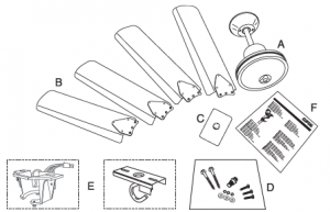
Hangsure Bracket or J-Hook Bracket
NOTICE
HAZARD OF INCORRECT ASSEMBLY
• To ensure proper balance, do not mix up blades with those from another fan as they are a matched set.• Transport and transit handling may loosen factory fitted cables. Please check and secure terminal screws before installation Failure to follow these instructions can result in equipment damage
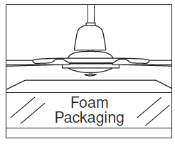
Protecting the Fan
HAZARD OF PRODUCT DAMAGE
- Do not place the motor directly onto a flat surface.
- The plastic nipple underneath the motor cannot support the weight of the motor and may be easily damaged. When working on the fan, place the motor on the foam packagingwith the nipple located in one of the recesses. This protects the nipple and the finish. Failure to follow these instructions can result in equipment damage

Controlling a Single Fan
This fan has been supplied with a Clipsal Three-Speed Controller that is designed to operate a single fan.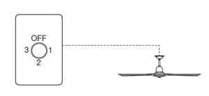
Multiple Fans on a Single Controller
Where multiple fans are required to be operated from a single controller, a Clipsal C-ThruTM Electronic Fan Controller(purchased separately) must be used.
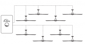
NOTICE
HAZARD OF INCORRECT USAGEThe three-speed fan controller supplied with each fan is not suitable for controlling multiple fans. Failure to follow these instructions can result in equipment damage
1.0 Mounting the Fan Support Bracket
WARNING
 WARNING
LOCATION HAZARD
- Select a suitable location to mount the fan support bracket.
- The mounting bracket must be fixed to a solid structural member, such as a ceiling joist or a securely fixed noggin, and be capable of supporting 15 kg.
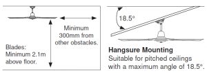
- Additionally, it is recommended to provide the blade with a minimum clearance from the floor of 2.1m, and from other obstructions of at least 300mm. Failure to follow these instructions can result in injury or equipment damage
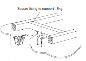
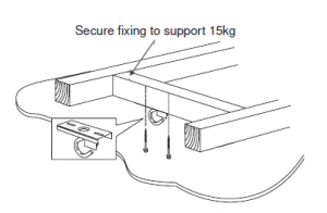
Hangsure Mounting J-Hook Mounting
Clearances and Angled Ceilings
2.0 Fitting the Blades
Place the blade over the motor and align screws. Securely tighten both screws.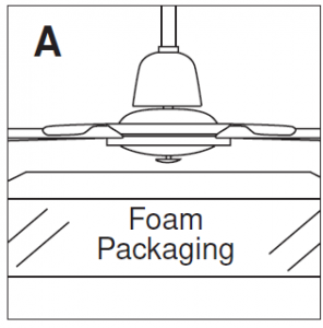
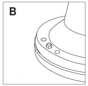
Support the motor Motor Screw Holes

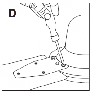
Slide blade over screws Tighten screws
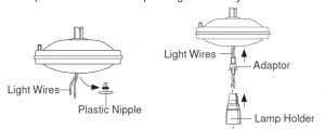
3.0 Connecting the Light Fitting
If you are attaching a light fitting to the fan, do so prior to hanging the fan.NOTE: Clipper Light or Oyster Light may be installed in fans that are constructed for this purpose.
- Unscrew the plastic nipple from the bottom of the motor housing.
- Pull out the light wires from the motor housing for connection with the lamp holder.
- Insert the light wires through the adaptor, then screw the adaptor into the motor shaft.
- Connect the light wires to the lamp holder then screw the lamp holder and the adaptor together firmly.
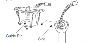
4.0 Hanging the Fan
Hangsure BracketPosition the ball-joint in the bracket so that the guide pin on the bracket engages in the slot in the ball-joint.
J-Hook BracketFit the rubber wheel assembly over mounting
HAZARD OF CEILING DAMAGEFor j-hook brackets, leave a 5-10mm gap between the ceiling and cowling. It’s normal for the cowling to move slightly when the fan is running. This gap prevents damaging the paintedceiling and prevents ticking or clicking noises. Failure to follow these instructions can result in equipment damage
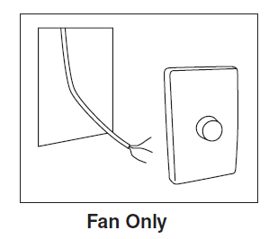
5.0 Connecting the Fan
All Airflow Ceiling Sweep Fans are pre-wired to allow for a light to be fitted onto the fan.If you are not fitting a light to the fan, please disregard the light wires. The wires are connected to the incoming wiring as illustrated in the below diagram.Means for all pole disconnection must be incorporated in the fixed wiring in accordance with the wiring rules.

6.0 Connecting the Speed Controller
All Airflow Ceiling Sweep Fans come complete with a three-speed flush fitting capacitor controller. This controller fits to standard 84mm fixing centres, the same as a normal switch or power point. Although supplied standard in the vertical format, the mechanism can be rotated 90° to provide a horizontal format if required. To ensure that the “off” position of the switch is at the top when installed, the mechanism must be installed into the plate with the three screw heads pointing upwards. The mechanism must be fully “clipped” into the plate from the rear. Three is the highest speed, one is the lowest.
- Remove switch surround.
- Terminate cables as illustrated in the below diagram.
- Active to common and switched active to terminal one.
- Fix controller to wallbox or bracket using screws provided.
- Screws may need to be shortened for some applications.
- Replace switch surround.
7.0 Connecting the Speed Controller with a Light Switch

Connecting the speed controller with a light switch requires additional components (not supplied with this fan) including:– Clipsal 30M Switch Mechanism– Two gang grid plate and cover.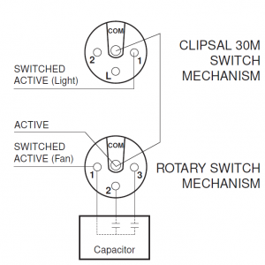
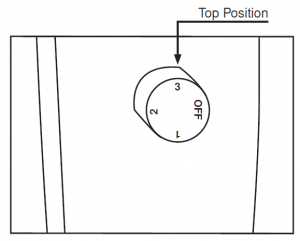
8.0 Operating Instructions
- Turn the knob to speed three (top position). This will start the blades spinning.
- Once the blades are spinning you can select a lower speed if desired.
- The speed setting is always located at the top position of the knob as illustrated below.
Summer/Winter Settings
The forward/reversible switch is located on the bottom cowl.

Check switch and make sure it is in correct setting, depending on cold weather or hot weather. Cold weather: Push switch down for the blades to circulate the warm air trapped near the ceiling. Hot weather: Push switch up for the blades to create a breeze and circulate the air.NOTE:The forward/reversible switch must be fully engaged for the fan to operate.
Cleaning Instructions
To clean the fan, wipe over with a damp, soapy cloth. Do not use scourers or abrasive cleaners.
Fan will not switch on.
- Switch off the fan. Then check the following:
- forward/reverse switch on fan motor not fully engaged in desired setting
- connections not as per installation diagram
- fuse blown, circuit breaker tripped or there is a power failure. Fan will not operate at varying speed control settings.
- Controller connections not as per page 3. Ticking, rattling, mechanical noises.
- Ensure all screws and bolts are tight.
- Ensure the mounting assembly is secure.
- Ensure the lower canopy is clear of the motor.
- With hook mount models, ensure the top canopy is clear of the ceiling by 5 to 10mm to allow for slight movement of the fan.
- Ensure the wires are not tapping against the canopy.
CAUTION
MOVING PARTS OR ELECTRICAL HAZARD
- Do not attempt to stop the blades by hand, even at low speed.
- This appliance is not intended for use by persons (including children) with reduced physical, sensory or mental capabilities, or lack of experience and knowledge, unless they have been given supervision or instruction concerning use of the appliance by a person responsible for their safety. Children should be supervised to ensure that they do not play with the appliance.
- Ensure all electrical supplies are disconnected before cleaning, maintenance and attachment of lamp kit. Failure to follow these instructions can result in injury or equipment damage
For further technical support contact the Clipsal National Customer Service Centre on 1300 2025 25.
Schneider Electric (Australia) Pty Ltd Contact us: clipsal.com/feedbackNational Customer Care Enquiries
Warranty
The benefits conferred by this warranty are in addition to all implied warranties, other rights and remedies in respect of the product which the consumer has under the Trade Practices Act and similar State and Territory Laws. The original purchaser of this Airflow Ceiling Sweep Fan, is provided with the following warranty, subject to the following conditions: Schneider (Australia) Pty Ltd warrant this product for a period of three years from the date of purchase for all parts defective in workmanship or materials. All products used in commercial applications are limited to a 90 day warranty. All defective parts will be replaced free of charge. The following exclusions do not preclude the purchaser from those statutory rights consumers haveunder the Trade Practices Act or similar State and Territory Laws.
WARRANTY CONDITIONS:
- This warranty is only valid for appliances installed according to the manufacturers instructions.
- This appliance must not be modified or changed in any way and all electrical connections must be carried out by a qualified electrician only.
- Connection must be to the voltage requirements as specified in the ratings label located on the product.
- The manufacturer does not accept liability for any direct or consequential damage, loss or other expense arising from misuse or incorrect installation and operation of the appliance.
- Warranty will only be given where proof of purchase is provided, e.g. original invoice.
- For warranty to be valid only Airflow accessories, such as down rods and light kits, shall be installed with the Airflow Ceiling Sweep Fan.
IMPORTANT
Record this warranty information at the time of purchase but do not send this information unless you are making a claim or are asked to do so. To obtain service under warranty you must retain your original purchase receipt, service will otherwise be charged at current rates.
Read More About This Manual & Download PDF:
References
[xyz-ips snippet=”download-snippet”]