
![]()
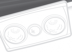
Fan, Light and Heater Unit
7600ATP
Fitting Instructions
This card is also your installation template.IMPROVED DESIGN now with ceramic lamp holders.


Thank you for purchasing this Clipsal product. Please install the product carefully, according to these instructions.
Clipsal 3-in-1 products combine an exhaust fan, light and gentle heat in one single unit. All functions switch separately from a supplied switch plate.
Safety, Installation and Operating Requirements
 DANGER
HAZARD OF ELECTRIC SHOCK, EXPLOSION OR ARC FLASH
- This product must only be installed and serviced by appropriately qualified and/or licenced electrical personnel.
- Isolate the electrical supply before doing any work on this product.
- Ensure that the product has been correctly installed and tested for safe operation before reconnecting the electrical supply.
- The product must be installed so that the switches and other controls cannot be touched by a person in the bath or shower.
Failure to follow these instructions will result in death or serious injury.
WARNING
RISK OF FIRE AND SERIOUS INJURY
- Do not install the product close to curtains or other combustible materials.
- Do not install the product directly below a socket outlet.
- Do not cover the product with insulating or other materials.
- Only install R125 275 W heat reflector globes in the heat cavities of the product.
- Do not install heat reflector globes greater than 275 W in the heat cavities of this product.
- Only install this product in strict accordance with the wiring diagram in these instructions.
Failure to follow these instructions can result in fire and serious injury.
CAUTION
IMPORTANT CLEANING SAFEGUARDS
- Ensure that the product is switched off before cleaning.
- Remove heat globes when they are at room temperature.
- Wipe with a damp cloth. Never immerse the globes in liquid.
- Always use a soft, non-abrasive cloth to clean the product.
- Regularly clean away excess fluff from inside the body, motor, blades and brackets.
Failure to follow these instructions can result in injury and equipment damage.
NOTICE
USAGE HAZARD
- Do not install the product directly over baths or showers or in areas subject to direct splashing.
- Do not leave heat reflector globes on for extended periods of time.
- For applications where the heat reflector globes may be left on for longer than 20 minutes, it is recommended to install a separate timer to automatically switch off the heat lamps.
- The product should not be covered or installed in locations that restrict natural ventilation for cooling purposes.
- Ensure that the product grille is kept free of objects, dust build-up and other matter that may restrict air flow.
Failure to follow these instructions can result in equipment damage or reduced lifespan of components.
NOTICE
INSTALLATION HAZARD
- This product is designed specifically for cavity-type ceilings.
- It is NOT recommended to install this product in flat-roof, raked or cathedral ceilings.
- The heat lamps are not designed to heat entire rooms, but rather apply instant, concentrated heat to persons standing directly below the product.
- It is recommended that the ceiling space is adequately ventilated to allow appropriate air flow through the unit. Any restrictions on return air entering the room or exhausted air escaping from the ceiling space will impair effectiveness and may contribute to premature failure.
- A minimum of 250 mm clearance is required above the ceiling where the product is to be installed.
- A minimum of 100 mm clearance is required between the installation location and any ducting in the ceiling space.
- Regulations regarding the discharge of air must be complied with.
- Joists, beams and rafters must not be cut or notched to install the product.
Failure to follow these instructions can result in reduced product performance or equipment damage.
THIS CARD IS ALSO YOUR INSTALLATION TEMPLATE
CAUTION
EQUIPMENT OPERATION HAZARD
- This product is not intended for use by persons (including children) with reduced physical, sensory or mental capabilities, or lack of experience and knowledge, unless they have been given supervision or instruction by a person responsible for their safety.
- Ensure that the switch is in the Off position before changing the centre globe or heat reflector globes.
Failure to follow these instructions can result in injury.
Installation
NOTICE
CORRECT INSTALLATION
- The lamp surround has been designed to position the heat globes correctly in the main body. Failure to position the lamp surround correctly may cause the heat globes to touch the main body and cause warping.
- The product’s centre cavity is designed to accept only R63 8 W LED reflector globes.
- Only install R63 8W LED reflector globes in the centre cavity. Do not install any other type of globe as this may cause overheating and subsequent warping of the body.
- The two heat cavities have been designed to accept only R125 275 W reflector globes. Do not install heat globes greater than 275 W.
- Do not force or over-tighten globes.
Failure to follow these instructions can result in equipment damage.
Mounting
MAJOR CLEARANCES
![]()
![]()
![]()
![]()
MOUNTING
A 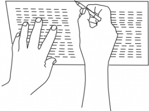 B
B 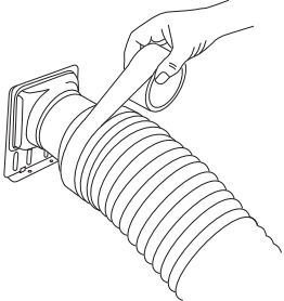 C
C 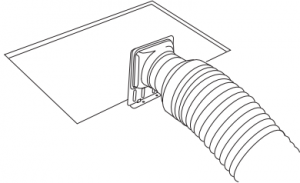
D  E
E  F
F 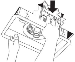
G  H
H  I
I 
J 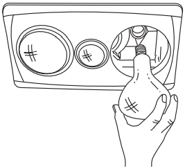
- (See diagram A) Using this card in its open state as a template, position it in the area you want to place your product and draw around the edges with a pencil to mark the hole cutting size.BE SURE TO CHECK ABOVE THE CEILING FOR A MINIMUM SPACE OF 250 mm OR MORE CLEARANCE AND THE LOCA-TION OF THE CEILING JOISTS.
- Use a saw to cut the section along the drawn lines.
- Lay the ducting and attach the duct adapter to the end of the duct-ing nearest the cut-out (see diagrams B and C).
- Remove the two (2) screws and terminal cover to access the terminal block (see diagram D). The 7600ATP uses screwless spring-type mounting clips to support the product on the ceiling. Before trying to install the product into the cut-out, unclip the lamp surround from the main body by disconnecting four (4) springs. Remove the lamp surround and the globes to avoid damage from knocks and vibrations.
- Position the main body at the cut-out and attach the duct/adapter to the top of the main body (see diagrams D and E).
- Fully insert the main body into the cut-out and ensure the springtype mounting clips support the main body on the ceiling. Use the supplied screws to fix the main body to the ceiling (see diagram F).
- Reattach the lamp surround by reconnecting the springs (see diagrams H and I). The lamp surround has been designed to position heat globes correctly in the main body. Failure to position lamp surround correctly may cause heat globes to touch the main body and cause warping. Screw centre light globe into place. This unit is designed to accept only R63 8 W LED reflector globes.
- Screw the two (2) large heat globes through the lamp surround holes, tightening firmly to ensure a good electrical contact. Use only R125 275 W globes as supplied with the product.
Wiring
The 7500ATP requires a 240 V a.c. 50 Hz electrical supply, and comes with all required wall and architrave mounting, switch plates and switches.
- Decide the best position for the switch set and mount it. Be sure to click the switches into the backing plate in the desired order beforehand.
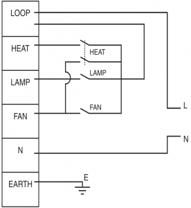
- Connect wiring switches as shown in the electrical diagram.
- Remove the electrical terminal cover and wire according to the label beside the terminal strip. Once the wires are connected, incoming cable must not be fouled by the cover. Remove cut-out portion as required and replace cover.
Spare Parts
Electrical switches supplied with your Clipsal 3-in-1 unit are usually available from any electrical wholesaler:
- Centre Globe: The centre globe can only be replaced with an R63 8 W LED reflector globe.
- Heat Globes: The heat reflector globes can only be replaced with R125 275 W heat reflector globes.
Technical Information
| Voltage | 240 V a.c. 50 Hz only |
| Fan Wattage | 580 W–630 W |
| Fan Max. Air Movement | 125 m3/hr (3 m ducting with 90° bend) |
THIS CARD IS ALSO YOUR INSTALLATION TEMPLATE
Customer care—AustraliaWe warrant this product for 2 years. For details, visit:https://www.schneider-electric.com.au/en/about-us/legal/terms-and-conditions.jsp
Our goods also come with guarantees that cannot be excluded under the Australian Consumer Law. You are entitled to a replacement or refund for a major failure and compensation for any other reasonably foreseeable loss or damage. You are also entitled to have the goods repaired or replaced if the goods fail to be of acceptable quality and the failure doe s not amount to a major failure.
Schneider Electric (Australia) Pty LtdCustomer Care: 1300 369 233Email: [email protected]www.schneider-electric.com.au
Customer care—New Zealand ![]()
https://www.schneider-electric.co.nz/en/about-us/legal/terms-and-conditions.jsp
Schneider Electric (NZ) LtdCustomer Care: 0800 652 999Email: [email protected]www.schneider-electric.co
Schneider Electric reserves the right to change specifications, modify designs and discontinue items without incurring obligation and whilst every effort is made to ensure that descriptions, specifications and other information in this catalogue are correct, no warranty is given in respect thereof and the company shall not be liable for any error therein.
© 2017 Schneider Electric.
This material is copyright under Australian, New Zealand and international laws. Except as permitted under the relevant law, no part of this work may be reproduced by any process without prior written permission of and acknowledgment to Schneider Electric.
References
[xyz-ips snippet=”download-snippet”]