
CLIPSAL Iconic Series PIR Motion Sensor
Mechanism Instruction Manual

DANGERHAZARD OF ELECTRIC SHOCK, EXPLOSION, OR ARC FLASH
- It is illegal for persons other than an appropriately licensed electrical contractors or other persons authorised by legislation to work on the fixed wiring of any electrical installation.
- To comply with all safety standards, the product must be used only for the purpose described in this instruction and must be installed in accordance with the wiring rules and regulation in the location where it is installed.
- There are no user serviceable parts inside the product.
Failure to follow these instructions will result in death or serious injury.
DANGERRISK OF ELECTRIC SHOCK
- Hazardous voltage and electrical current may be present at the wire leads of this product even when the device is switched off.
- Lock out and tag the input circuit before accessing the wiring connections.
- A circuit breaker (250 V a.c. 10 A) Type C must be installed according to AS/NZS 60898.
- Use a terminal block to connect the PIR Mechanism to the electrical circuit.
- After wiring, wrap the terminal block with insulating tape.
Failure to follow these instructions will result in death or serious injury.
CAUTIONEQUIPMENT DAMAGE HAZARD
- Install the device according to instructions in this document.
- Pay attention to the specifications and wiring diagrams related to the installation.
- Do not use this product for any other purpose than specified in this instruction.
Failure to follow these instructions can result in minor injuries, or equipment damage.
NOTICERISK OF EQUIPMENT DAMAGE OR MALFUNCTION (WIRING CONNECTIONS)
To avoid damaging the equipment and possibly voiding the warranty:
- Test operation during installation and correct any wiring errors immediately.
- Keep cable insulation away from the sides of the enclosure to avoid possible damage or long term degradation of the cable insulation.
Failure to follow these instructions can result in equipment damage or malfunction.
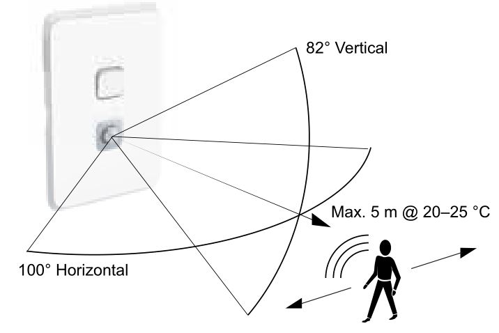
Detection pattern and range
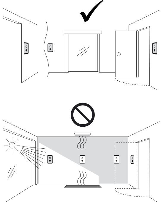
Sensor locations
Installation example: hallway
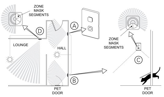
A. 1× sensor to cover hallway front entrance.B. 1× sensor to cover hallway back entrance.C. Zone mask used to prevent detection near the pet door.D. Sensor covering lounge area. Zone mask used to prevent detection in the hallway zone. (See Zone masking.)
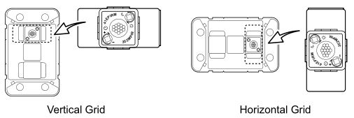
Orientation for multi-gang installation
Fitting the PIR mechanism to the grid

- Open the locking bar (A).
- Push the head of the PIR mechanism into the grid aperture until the head clicks into place B.
- Close the locking bar (C).
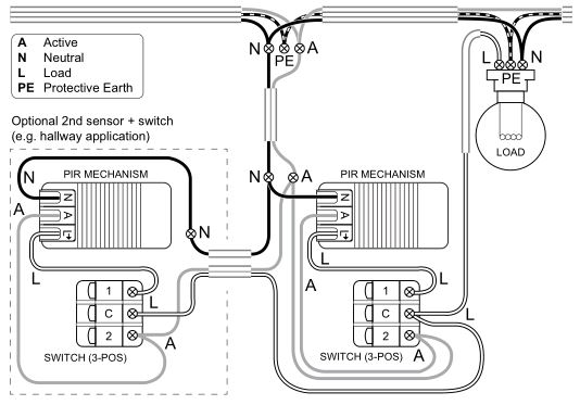
Cabling and connections
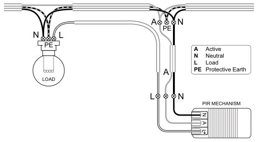
Single PIR mechanism
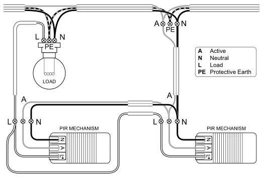
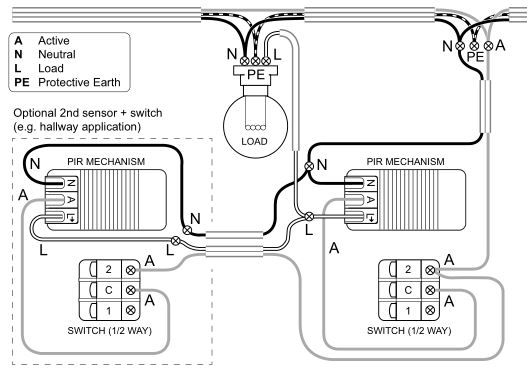
2× PIR mechanisms (e.g. hallway application)
Securing the PIR mechanism fly leads
Note: Ensure that the PIR mechanism fly leads are tied back or otherwise secured in accordance with the wiring rules and regulations that apply in the location where the mechanism is installed.
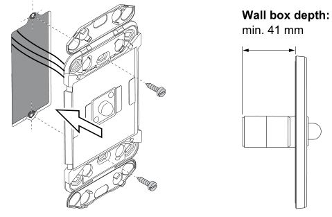
Mounting the grid
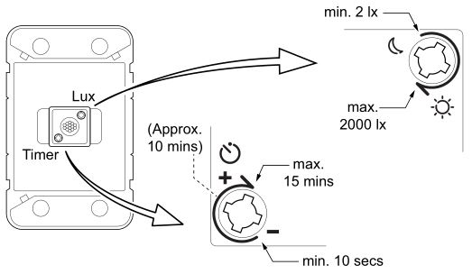
Adjusting the timer and lux settings
Zone masking
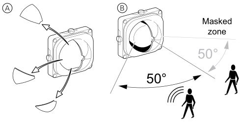
- Remove zone mask segments to allow sensor to detect movement A.
- Remaining segments prevent detection of movement B.
Fitting the carrier or zone mask to the skin
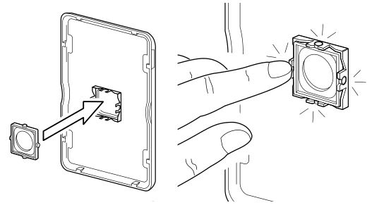
Installing the skin
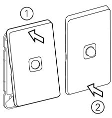
Removing the skin

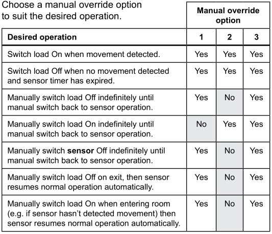
Manual override options
Depending on the wiring and the type of switch used, the following manual override options are possible:
Option 1: Manual override activated by the sensor using a rocker switch.Option 2: Manual override bypassing the sensor using a rocker switch.Option 3: Manual override with 3-position switch.
Manual override option 1
Add a 1/2 way switch.
Sensor-activated override
- Toggle the switch to position B and back to A within 1.5 seconds.
- Sensor toggles the load state On or Off and maintains that state for the duration of the sensor timer setting.
- Sensor resumes normal operation once timer expires.
Note: If power to sensor is interrupted for 1.5 seconds, the load is switched on for about 1 minute, then sensor resumes normal operation.
Manual OFF• Operate switch to position B (turns sensor and load Off).• Operate switch to position A to resume sensor operation.
Cabling and connections for option 1
Manual override option 2
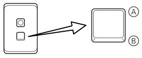
Add a 1/2 way switch. Labelled dolly recommended (“Auto/Manual” shown).

Manual ON• Operate switch to position B to override sensor and keep load On.• Operate switch to position A for normal sensor operation.
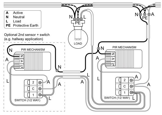
Cabling and connections for option 2
Manual override option 3
Add a 3-position switch. Labelled dolly recommended (“Sensor/Off/On” shown).
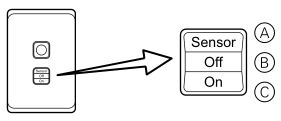
Manual OFF• Operate switch to position B (turns sensor and load Off).• Operate switch to position A to resume sensor operation.
Manual ON• Operate switch to position c to override sensor and keep load On.• Operate switch to position A for normal sensor operation.
Cabling and connections for option 3
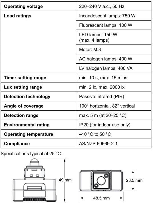
Technical specifications
Customer care
Warranty informationWe warrant this product for 2 years. For details, please visit http://www.schneider-electric.com.au/en/about-us/legal/terms-and-conditions.jsp.
Our goods also come with guarantees that cannot be excluded under the Australian Consumer Law. You are entitled to a replacement or refund for a major failure and compensation for any other reasonably foreseeable loss or damage. You are also entitled to have the goods repaired or replaced if the goods fail to be of acceptable quality and the failure does not amount to a major failure.
![]()
Schneider Electric (Australia) Pty LtdCustomer Care Australia: 1300 369 233Email: [email protected]www.schneider-electric.com.au
Schneider Electric reserves the right to change specifications, modify designs and discontinue items without incurring obligation and whilst every effort is made to ensure that descriptions, specifications and other information in this catalogue are correct, no warranty is given in respect thereof and the company shall not be liable for any error therein.
© Schneider Electric 2017
This material is copyright under Australian and international laws. Except as permitted under the relevant law, no part of this work may be reproduced by any process without prior written permission of and acknowledgement to Schneider Electric.
F2842
October 2017
References
[xyz-ips snippet=”download-snippet”]