CLIPSAL Light Level Detector Surface Mount Installation Guide
Introduction
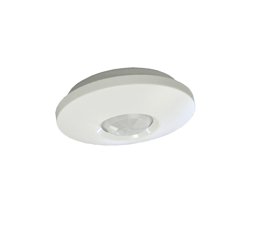
The 5754PE Light Level Detector is a C-Bus input unit that measures the ambient light level and converts this information into messages that are sent across the C-Bus network. Ambient light levels are compared to the user-defined target light level. Control messages are then sent to output units to alter the lighting levels as required, for example, using the RAMP TO LEVEL command issued to a dimmer unit. The surface mount detector is designed for mounting on stone or concrete or any location where it is not practical to install other types of detectors. The 5754PE is held in place by two screw anchors. The detector is powered by the C-Bus network and does not require a separate power supply unit. The 5754PE is an Extra Low Voltage (ELV)/Class 2 device.
Safety and Product Handling
The light level detector is for indoor use only with C-Bus systems. It is never connected to building power or an external power supply. Read and follow all instructions found on the product and its packaging.
WARNING Avoid Electrical ShockDo NOT connect the unit to building power or any telephony or Internet equipment. The detector is a Class 2, extra low voltage (ELV) device. Do NOT connect the unit to an external power supply or a non-C-Bus network.Use caution when drilling holes in ceilings. Check for the presence of electrical wiring and water pipes before drilling.
Caution Sensitive Components InsideStatic discharge and rough handling can damage the components on the circuit board. Use anti static procedures when handling the opened unit. Avoid touching the photo sensor and other electronic components.Changes or modifications not expressly approved by Clipsal could void the user’s authority to operate the equipment (under FCC rules).
Caution Avoid Damage to the LensThe fresnel lens is easily scratched. Scratches on the lens will reduce the accuracy of the detector. Use care when installing and configuring the unit.
Installation
The detector is for indoor use only. Do not place the unit where it will be exposed to dripping water, steam or direct sunlight. During the installation process, do not remove the lens from the top cover. To install the light level sensor you will need 2 fasteners to secure the unit to the ceiling. Select hardware suited to the mounting surface. Screws or anchors are not provided with the detector.
Removing the Top CoverThe detector housing consists of two pieces, the base and the cover. No tools are required to remove the cover. To remove the top cover grasp the base with one hand and rotate the top anti-clockwise with your other hand. Refer to the illustration below: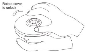
Figure 1. Removing the top cover To install the cover, make sure the tabs are aligned with the slots and rotate the cover clockwise until it locks in place.Installing the Mounting HardwareThe base of the detector is secured in two places (see Figure 2). Drill the holes for the screws or anchors and then follow instructions for mounting the detector.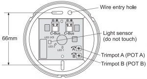
Figure 2. Mounting hole locations in the base.
Mounting the DetectorPass the network cable through the wire entry hole and then attach the detector’s base to the ceiling using the two screws or anchors as described in Section 3.2. The network wiring to the detector must be supported properly.
Connecting the C-Bus Network WiringUse Cat 5e Unshielded Twisted Pair (UTP) C-Bus cable. The use of bootlace ferrules (crimps) for screw terminals is recommended for a reliable connection. C-Bus cable conductor assignments are provided in Table 1. The Clipsal catalogue numbers for the C-Bus network cable is 5005C305B (solid conductors) and 5005C305BST (stranded conductors).
|
Pin |
C-Bus Connection |
Colour |
|
1 |
Remote ON | green & white |
|
2 |
Remote ON | green |
|
3 |
C-Bus Negative (–) | orange & white |
|
4 |
C-Bus Positive (+) | blue |
|
5 |
C-Bus Negative (–) | blue & white |
|
6 |
C-Bus Positive (+) | orange |
|
7 |
Remote OFF | brown & white |
|
8 |
Remote OFF | brown |
Table 1. C-Bus network cable conductor definitions
The C-Bus network uses polarised twisted wire pairs. The detector has two removable screw-type connectors. Strip the insulation from the twisted pairs and then connect the C-Bus positive (+) and C-Bus negative () twisted pairs to the screw terminals as shown in Figure 3.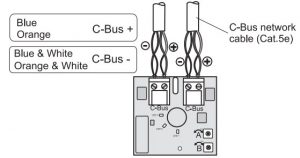
Figure 3. C-Bus wiring diagramPush the terminal plugs onto the pins on the circuit board. It is recommended that you seal the entry hole area with silicon rubber to keep dust and debris out of the detector. Install the top cover by aligning the tabs on the slots and rotating the top cover in a clockwise direction.Note: The Remote On and Remote Off signals are not used on the detector, but you should maintain these signal connections throughout the network.
Programming
The detector unit must be programmed with a unique unit address. This is done using C-Bus Toolkit software, available at the Clipsal Integrated Systems (CIS) web site, http://www.clipsal.com/cis. Go to the Technical section and select ‘Downloads. The adjustable trimpots (Trimpot A and Trimpot B) work in conjunction with C-Bus programming parameters to set the operating mode for the unit:
During programming, selectable group addresses are assigned for the following:
- Light level target
- Light level margin
- High lux level
- Low lux level
Programming can also define a selectable block for High/Low lux levels that can be controlled by a group.
- Light level threshold
- Light level margin
- Low level threshold
- High level threshold
The C-Bus Group controls the high and low lux levels. Where a parameter is controlled by a C-Bus group, the value of the parameter is defined as: Value defined in Toolkit x Percentage of C-Bus Group x Percentage of POT (if assigned).Refer to C-Bus Toolkit Help files for additional information about setting the target light level using the GUI.
Field Calibration
For lighting control applications, the light level sensor must be calibrated to attain the desired target illumination level. Enter the desired lux value using the Toolkit GUI to directly specify the target ambient light level in lux. Keep the cover on the unit when performing tests. Remove the cover to adjust the trimpots, as required, and then replace the cover. Using a hand held light meter can be helpful when making adjustments in specific areas, such as workstations or conference rooms.Note: Care must be taken to ensure proper accounting for any resulting offset. Take into account that the light level at work surfaces will be different from the ambient light level present at the sensor unit due to proximity to light sources, shadows or diffusion effects. Refer to Toolkit Help for detailed information about light level sensors.
Caution. Avoid Lens DamageThe fresnel lens is easily scratched. Scratches on the lens will reduce the accuracy of the detector unit. Use care when handling the top cover.
POT A, Light Level Adjustment, Trimpot A on the PCB is a potentiometer that adjusts the light level for calibration and for setting levels used when programming the unit with the Toolkit GUI.POT B, Light Level Threshold Adjustment, Trimpot B adjusts the light level threshold for the ambient light in the measured area.LED 1, Status of group. This orange LED is on when the assigned network group is active.LED 2, Light level maintenance active LED. This red LED is on when light level monitoring is active, so the unit will be actively monitoring the lighting level and controlling a group to keep the light level in the monitored area within Light Level Target +/- Light Level Threshold. To set the light level, follow these steps:
|
1. |
Connect the detector to the C-Bus Network and allow a few seconds for the unit to stabilize. Remove the top cover by rotating it in an anti-clockwise direction. |
|
2. |
Turn POT A to its maximum value, fully clockwise. Do not force the adjustment screw beyond its range of travel. This setting allows the detector to respond to ambient light depending on the current C-Bus toolkit setting. |
|
3. |
Install the cover. Using C-Bus Toolkit software, set the target light level to the selected value and set up the detector to control a load with Sunset function. In this case there is no need to set a timer. The load will turn on when the Light Level is less than Target – Threshold and it will turn off when the Light Level is greater than Target + Threshold. |
|
4. |
Remove the cover and adjust POT A (turning anti-clockwise) as necessary to take advantage of ambient light. The cover must be in place during testing. |
|
5. |
Adjust POT B as necessary for the desired threshold. After making setting changes to the pots, replace the cover and recheck the operation of the detector. |
Specifications
| Parameter | Description |
| C-Bus Voltage | 15 – 36V d.c. polarised, Class 2 |
| Current Requirement | 15mA sourced from the C-Bus network. The unit does not supply power to the network. |
| Maximum units per network | 100 |
| C-Bus connection type | 2 x 2-screw terminal block |
| Sensor type | Photocell |
| Detection pattern | 360° |
| Light level range | 0 – 1500 lux |
| Indicators | Red LED, light level maintenance is active Orange LED, assigned network group is active |
| Controls | Trimpot A (POT A), light level adjust
Trimpot B (POT B), light level threshold adjust |
| Warm up time | 5 seconds |
| Mounting location | Indoors only, ceiling mounted |
| Operating temperature | 5 to 50° C |
| Operating humidity | 10 to 90% RH |
| Weight | 68.5g |
Standards Complied
DECLARATIONS OF CONFORMITY
Australian/New Zealand EMC & Electrical Safety Frameworks and Standards
| Standard | Title |
| AS/NZS CISPR22 | Information technology equipment – Radio disturbance characteristics – Limits and methods of measurement |
European Standards
| Standard | Title |
| EN 55022
EN 55024 |
Information technology equipment – Radio disturbance
characteristics – Limits and methods of measurement. Information technology equipment – Immunity characteristics – Limits and methods of measurement |
USA Standards
Standard FCC Part 15 Radio Frequency Devices, Subpart B for unintentional radiators.
This device complies with Part 15 of the FCC Rules. Operation is subject to the following two conditions: (1) this device may not cause harmful interference, and (2) this device must accept any interference received, including interference that may cause undesired operation. Changes or modifications to this device that are not expressly approved by Clipsal or Schneider Electric could void the user’s authority to operate the equipment.Supplemental InformationThis device complies with part 15 of the FCC Rules. Operation is subject to the following two conditions: (1) this device may not cause harmful interference, and (2) this device must accept any interference received, including interference that may cause undesirable operation.Class B ProductNOTE: This equipment has been tested and found to comply with the limits for a Class B digital device, pursuant to Part 15 of the FCC Rules. These limits are designed to provide reasonable protection against harmful interference in a residential installation. This equipment generates, uses and can radiate radio frequency energy and, if not installed and used in accordance with the instructions, may cause harmful interference to radio communications. However, there is no guarantee that interference will not occur in a particular installation. If this equipment does cause harmful interference to radio or television reception, which can be determined by turning the equipment off and on, the user is encourage to try to correct the interference by one or more of the following measures:
- Reorient or relocate the receiving antenna
- Increase the separation between the equipment and receiver
- Connect the equipment into an outlet on a circuit different from that to which the receiver is connected
- Consult the dealer or an experienced radio/TV technician for help
Warning: Any changes or modifications not expressively approved by Schneider Electric (Australia) Pty Ltd could void the user’s authority to operate this equipment.
Other International Standards
| Standard | Title |
| CISPR 22
CISPR 24 |
Information technology equipment – Radio disturbance characteristics – Limits and methods of measurement
Information technology equipment – Immunity characteristics – Limits and methods of measurement |
Warranty Statement
The C-Bus Surface Mount Light Level Sensor carries a two-year warranty against manufacturing defects.Warranty StatementThe benefits conferred herein are in addition to, and in no way shall be deemed to derogate; either expressly or by implication, any or all other rights and remedies in respect the Clipsal by Schneider Electric product, that the consumer has under the Commonwealth Trade Practices Act or any other similar State or Territory Laws.The warrantor is Schneider Electric Industries SAS, with registered offices worldwide.This Clipsal by Schneider Electric product is guaranteed against faulty workmanship and materials for a period of two (2) years from the date of installation.Schneider Electric reserves the right, at its discretion, to either repair free of parts and labour charges, replace or offer refund in respect to any article found to be faulty due to materials, parts or workmanship.This warranty is expressly subject to the Clipsal by Schneider Electric product’s having been installed, wired, tested, operated and used in accordance with the manufacturer’s instructions.Schneider Electric shall meet all costs of a claim. However, should the product that is the subject of the claim be found to be in good working order, the claimant shall meet all such costs.When making a claim, the consumer shall forward the Clipsal by Schneider Electric product to the nearest office of Schneider Electric (Australia) Pty Ltd or Schneider Electric with adequate particulars of the defect within 28 days of the fault occurring. The product should be returned securely packed, complete with details of the date and place of purchase, description of load, and circumstances of malfunction.For all warranty enquiries, contact your local Clipsal by Schneider Electric or Schneider Electric sales representative. The address and contact number of your nearest office can be found at http://www.clipsal.com/locations or by telephoning the CIS Technical Support Hotline 1300 722 247 (Australia only).
Technical Support and Troubleshooting
For further assistance in using this product, consult your nearest Clipsal by Schneider Electric Sales for Technical Support Office.Australia Technical Support Hotline 1300 722 247 New Zealand Technical SupportHotline 0800 888 219 United States Customer Information Center1 888 778 2733 lighting Technical Support email:
Schneider Electric (Australia) Pty LtdContact us clipsal.com/feedbackNational Customer Service EnquiriesTel 1 300 2025 25 Fax 1 300 2025 56
References
[xyz-ips snippet=”download-snippet”]