CLRACING F7 DUAL V2
The Flight Controller for RACERS
Main Features
- MCU: STM32F722RET6216MHz
- DUAL 6-Axis ICM20602Separated Interrupts
- Build in Beta flight OSD
- Up to 8S(36V) direct battery
- Build in Voltage monitoring resistor
- Build in 5V/3A BEC and 3.3V
- Led strip share 5V with 5V/3.0A
- 5V OR VBAT, camera and VTX POWER VIA Pit Switch
- 6 Full UARTS: UART1, UART2
- Buildin Camera Control pin wi camera connection
- Buzzerpads for external buzzer
- VBAT Polarity protection
- Build in 32MB Blackbox flash chip
- M4 Can be selected either led strip signal or M4 signal for RPM filtering
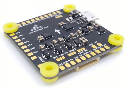
General Overview
- FC TOP VIEW

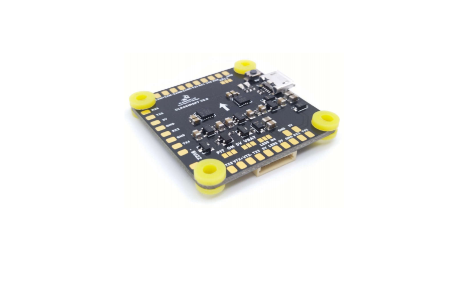
- FC BOTTOM VIEW

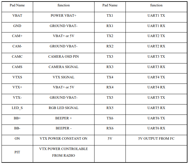
- FC + 4in1 ESC

 FC + 4in1 ESC


BETAFLIGHT SETUP
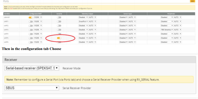
- SbusChoose UART 5 AS Serial RX, Solder your sbus signal to RX5 pad

- RX Voltage selection Jumper
 Solder on the left will output 5v , Solder the jumper on the right will output 3.3V
 - Smart port telemetryChoose UART1 AS Smart port on the telemetry output, then go to CLIEnter set tlm_halfduplex = OFF,Save

- Use True Pit mode for Team racingVBAT and 5V jumper control both VTX power and Camera PowerFirst Solder Jumper pad on PIT side
 Then go to CLI Copy the following command to the CLIresource PINIO 1 A14set pinio_box = 39,0,0,0savewait for the FC reboot then go to “modetab “set VTX PIT MODE on a AUX switch you prefer
 CAUTION: when using PIT mode, FC power up will not power your VTX until you turn on the switch on your radio you assigned to the VTX PIT mode
 - Use LEDS signal for Motor 4 enable RPM filteringFor normal use solder the jumper on the M4 side.
 For RPM FILTERINGSolder Jumper pads to the LEDS side, LEDS pad will be output as motor 4.In the CLI type inresource MOTOR 4 noneresource LEDS_STRIP 1 noneresource motor 8 noneresource MOTOR 4 B01savenow you can go ahead use the RPM filtering setting from BF wiki to enable RPM filtering feature
CLRacing F7 Dual V2 Flight Controller Manual – CLRacing F7 Dual V2 Flight Controller Manual –
[xyz-ips snippet=”download-snippet”]

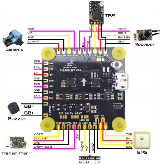
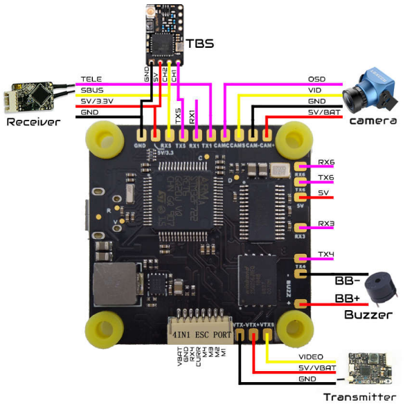
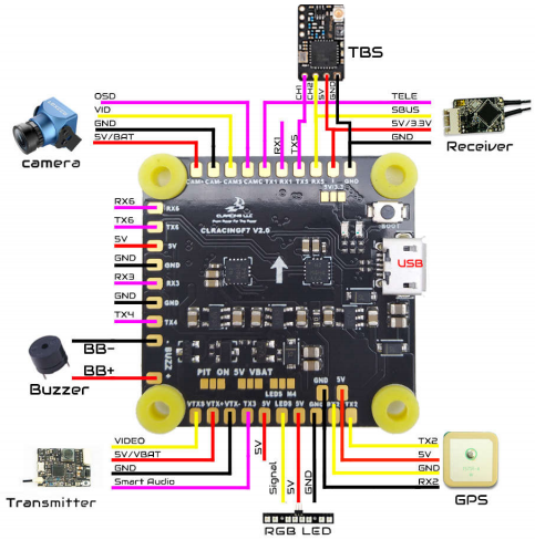
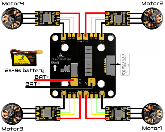 FC + 4in1 ESC
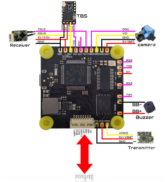
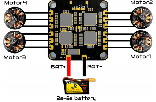
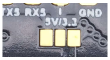 Solder on the left will output 5v , Solder the jumper on the right will output 3.3V
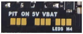 Then go to CLI Copy the following command to the CLIresource PINIO 1 A14set pinio_box = 39,0,0,0savewait for the FC reboot then go to “modetab “set VTX PIT MODE on a AUX switch you prefer
 CAUTION: when using PIT mode, FC power up will not power your VTX until you turn on the switch on your radio you assigned to the VTX PIT mode
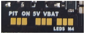 For RPM FILTERINGSolder Jumper pads to the LEDS side, LEDS pad will be output as motor 4.In the CLI type inresource MOTOR 4 noneresource LEDS_STRIP 1 noneresource motor 8 noneresource MOTOR 4 B01savenow you can go ahead use the RPM filtering setting from BF wiki to enable RPM filtering feature