INTRODUCTION
Thank you for purchasing the Cobra POWER 500W Power Inverter (Model CPI500W). Used properly, this Cobra product will give you reliable power to run your appliances and devices. Please read this manual thoroughly before you install and set up your new power inverter.
HOW DOES YOUR POWER INVERTER WORK
The Cobra POWER 500 Power Inverter is a power conversion device that is designed and built to operate from low voltage DC (Direct Current) power from your vehicle battery and converts it to standard 115 Volt AC (Alternating Current) power like you have in your home. This conversion process allows you to use many of your household appliances and electronic products in automobiles, RVs, boats, trucks, and virtually anywhere else with a 12 Volt battery.
PRODUCT SERVICE AND SUPPORT
For any questions about operating or installing this new Cobra product, PLEASE CONTACT COBRA FIRST…do not return this product to the retail store. The contact information for Cobra will vary depending on the country in which you purchased and utilize the product. For the latest contact information, please go to www.cobra.com/support or call 1-800-543-1608.If your product should require factory service, please go to www.cobra.com/support and follow the instructions.
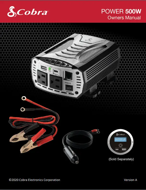
WHAT’S IN THE BOX
- Cobra CPI500W Power Inverter
- 16” #10 AWG Power Cables
- 16” 12-Volt Accessory Cable
- Quick Start Guide
OPTIONAL ACCESSORIES – available at www.cobra.com
- CPIALCDG1 – Remote On/Off controller with Fast Charge USB
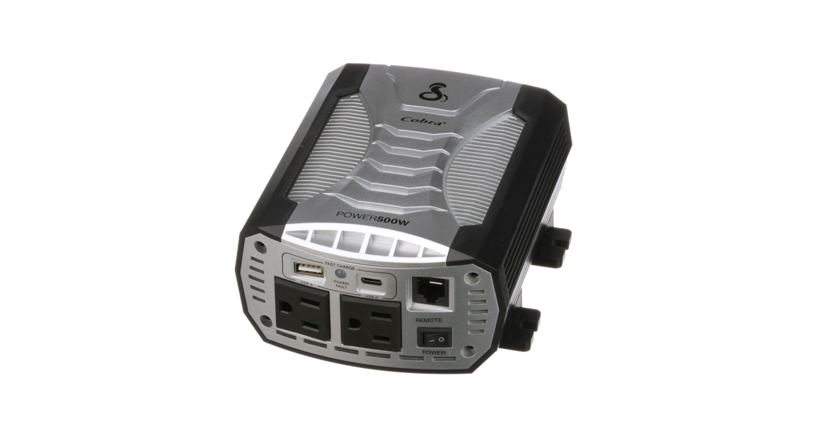
CONTROLS AND CONNECTIONS
A. Negative Power Input TerminalB. Cooling Fans – regulate the temperature of the inverter, turning on when the temperature exceeds the preset limit and turning off when the temperature reducesC. Positive Power Input TerminalD. USB-A Fast Charge port (5V/9V/15W)**E. Power/Fault LED IndicatorF. USB-C Fast Charge port (5V/9V/15W)**G. Port for Cobra Remote On/Off Controller with Fast Charge USB (Sold Separately)*H. (2) GFCI Protected AC OutletsI. Power SwitchJ. Power CablesK. 12 Volt Accessory Cable (for vehicle accessory port)L Cobra Remote On/Off Controller with Fast Charge USB (Sold Separately)*** = Fast Charge works only on devices capable of supporting a charge up to 10W
IMPORTANT PRODUCT /SAFETY INFORMATION
Before installing and using your Cobra power inverter, please read these general precautions and warnings.Caution and Warning Statements Special attention must be paid to the CAUTION and WARNING statements in the manual.CAUTION: Statements specify conditions that could cause damage to the unit or other equipment.WARNING: Statements identify conditions that could result in personal injury or loss of life.General Precautions
- Never install the inverter in a boat’s engine compartment where gas and battery fumes are present.
- Do not operate the inverter if it has been dropped or damaged in any way.
- Do not open the inverter; it contains no user-serviceable parts. Attempting to service the unit could cause electrical shock.NOTE: Internal components remain charged after all power is disconnected.
- Do not expose the inverter to rain, snow, bilge water or spray.
- Do not obstruct the ventilation openings.
- Do not install the inverter in a zero-clearance compartment.
- Do not allow water or liquids in contact with the power inverter
- Do not use appliances with damaged or wet cords.
CAUTION: This inverter should be used in negative ground applications only.CAUTION: The inverter must only be connected to batteries with a nominal output voltage of 12 volts. Do not connect the power inverter to a 6 Volt battery and will be damaged if connected to a 24 Volt battery.WARNING: Power inverters contain components that tend to produce arcs or sparks. To prevent fire or explosion, do not install the inverter in areas or compartments containing batteries or flammable materials or in locations that require ignition-protected equipment.WARNING: To avoid fire, do not cover or obstruct the ventilation openings. Do not install the power inverter in a tight space or closed compartment where airflow may be restricted.Proposition 65: Warning: Wash Hands After Handling Power Cord The power cord on this product contains lead, a chemical known in the state of California to cause birth defects or other reproductive harm.
Caution: Rechargeable Appliances
Certain chargers for small nickel-cadmium batteries can be damaged if connected to a Cobra POWER 500W inverter. Two particular types of equipment are prone to this problem:
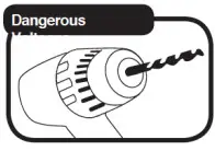 1. Small battery-operated appliances such as flashlights, razors, and night lights that can be plugged directly into an AC receptacle to recharge.2. Certain battery chargers for battery packs used in hand power tools. These chargers have a WARNING label stating that dangerous voltages are present at the battery terminals.
This problem does not occur with the vast majority of battery-operated equipment. Most use a separate charger or transformer that is plugged into the AC receptacle and produces a low voltage output. If the label on the AC adapter or charger states that it produces a low voltage AC or DC output (less than 30 volts), the inverter will have no problem powering the adapter safely.Cobra 500W Output WaveformSome very sensitive electronic equipment may not operate satisfactorily on the output waveform referred to as “modified sine wave” which this inverter is designed. It is a stepped waveform designed to have characteristics similar to the sine wave shape of utility power. A waveform of this nature is suitable for most AC loads (including linear and switching power suppliers used in electronic equipment, transformers, and motors).
PENTAGON PROTECTION®
Cobra power inverters provide five levels of protection:
- Over-Temperature: Auto-shutoff will occur when the safe operating temperature has been exceeded.
- Reverse Polarity: The inverter will not operate if connected incorrectly to the power source.
- Over-Voltage: Auto-shutdown will occur if the DC input exceeds safe operating levels.
- Low Voltage Alarm: The inverter will sound an alarm to indicate a low battery voltage condition.
- Low Voltage Cutoff: The inverter will automatically shut off to prevent a dead battery condition.For detailed specifications go to the Specifications section of this manual, starting on page 18.
GETTING STARTED
This section provides you with basic information about the inverter and a few tips before installation.To get started, you will need:
- A 12 Volt DC battery (i.e. vehicle battery. In order to understand how much current your battery must deliver, divide the number of Watts from your AC appliance or device by 10.
- Cables to connect your inverter to the vehicle battery. These come with your POWER 500W Inverter and provide a length of 16″.
DETERMINING THE POWER REQUIREMENTS FOR YOUR PRO INVERTER Before you turn on your power inverter and plug in an appliance or device, you will want to understand its power requirements.To determine the requirements, you will need to know the Watts of your device. This can be calculated by multiplying the Amps by 110 Volts (See Below).
POWER CONSUMPTION
For each piece of equipment, you will be operating from the power inverter, you must determine the battery’s reserve capacity (how long the battery can deliver a specific amount of current – in automotive batteries, usually 25 amperes) or ampere-hour capacity (a measure of how many amperes a battery can deliver for a specified length of time).Example – Ampere-hour capacity: a battery with an ampere-hour capacity of 100 ampere-hours can deliver 5 amperes for 20 hours before it is completely discharged.To determine the battery Ampere-hour capacity you require:
- Determine how many Watts each piece of equipment consumes. This can normally be found on the product label. If only the Amperage is provided, then multiply the Amps by 115 to determine the power in Watts.
- Estimate how long you need your appliance to run.
- Now calculate the Amp-hour rating for the battery. You can do this by multiplying the total AC load (in Watts) by the length of time (in Hours) needed to run your appliance. This will give you the Watt-Hours needed.

- Divide the watt-hours by 10 to determine how many battery (12 volts) ampere-hours will be consumed.
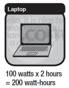
Multiply: AC AMPS X 110 (AC Voltage) = WATTS. This formula yields a close approximation of the continuous load of your appliance.Multiply: WATTS X 2 = Starting load for most appliances, tools, and devices. This formula yields a close approximation of the starting load for most appliances. Exceptions are motorized appliances such as pumps, freezers, and air conditioners. These appliances can have startup loads of up to eight times the rated Watts.For electrically sensitive equipment, contact the manufacturer to determine if the device you are using is compatible with a modified sine wave AC. If not, then a Pure Sine Wave Inverter is recommended.Determining the DC Power RequirementsYour power inverter requires the input of a 12-Volt battery. To calculate the approximate power in Amps as a 12-Volt battery bank you need to know the current, or Amps required for powering the continuous AC load. A shortcut method is to divide the continuous AC load Wattage by 10. For example, the continuous AC load is 500 Watts. The current (Amps) is: 500/10 or 50 Amps at 12VDC. Add to the load any DC appliances that may be powered by the battery bank.
MOUNTING THE INVERTER
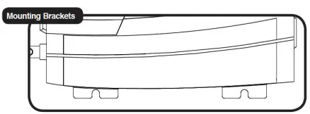
Do not mount the power inverter under the hood of any vehicle. Choose a cool, dry, and well-ventilated area inside the vehicle as close to the battery as possible. Place the power inverter on a flat, secure surface. Make sure there are no wires, fuel lines or fluid tanks directly behind the wall or surface being drilled. When mounting, secure the power inverter in place using corrosion-resistant mounting hardware (not included).
What you will need:
- Assess your mounting needs depending on the inverter and type of surface you are mounting (i.e. wood or fiberglass)
- Gather the necessary tools depending on the surface (i.e. drill or screwdriver)
- Determine the size of mounting hardware. Use only corrosive resistant screws (not included
Mounting Instructions:
- Make sure the inverter is OFF.
- Check for wires, fuel lines or fluid tanks behind the wall or surface you plan to drill.
- Position the power inverter horizontally when choosing the mounting location. If mounted on a wall be sure the front of the inverter is facing out. Do not mount vertically to prevent debris or dust from falling into the power inverter.
- Mark the locations of the mounting screws before drilling.
- Remove the inverter and drill the (4) mounting holes.
- Fasten the inverter to the mounting surface using corrosion-resistant screws (not included).
POWER 500W INSTALLATION
CONNECTING TO THE BATTERY
- Mount the inverter inside the vehicle in a well-ventilated location close to the battery.
- Disconnect the NEGATIVE (-) or black battery terminal of the vehicle.
- Route cables close to the battery.
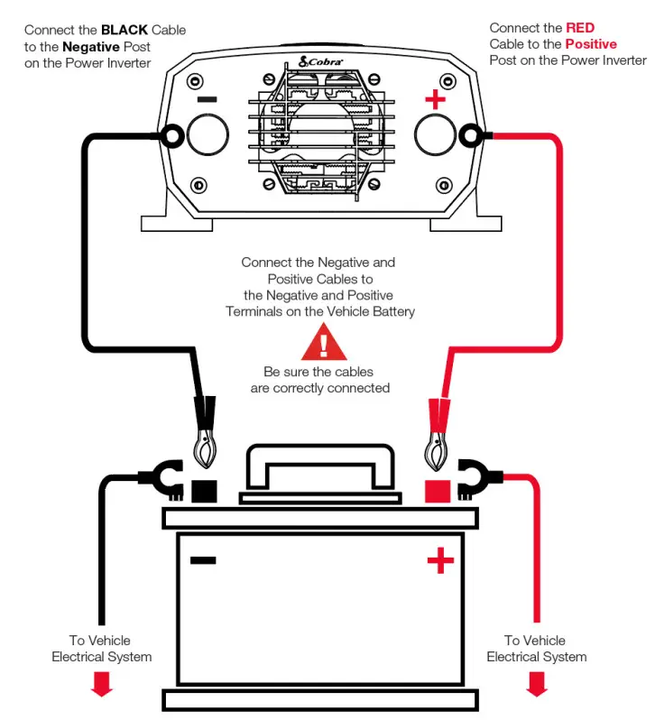
- Install the insulated terminal boots on the inverter end of the power cables (RED = positive, BLACK = negative).
- Connect the BLACK Cable to the Negative (-) terminal on the inverter.
- Connect the RED Cable to the Positive (+) terminal on the inverter.
- Connect the other end of the RED cable to the (+) terminal on the vehicle battery.
- Visually inspect and make sure the red wire or its connectors are not touching any metal parts of the vehicle or the black wire connectors.
- Connect the other end of the BLACK cable to the (-) terminal on the vehicle battery. Caution: There is normally a spark at the point of contact at the negative terminal.
- Check all connections making sure the RED cable is connected to the POSITIVE (+) terminals and the BLACK cable is connected to the NEGATIVE (-) terminals.
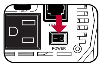
- Press the POWER button to turn on your inverter.
- If you purchased the Cobra Remote On/Off Remote Controller with Fast Charge USB (Model CPIALCDG1) accessory, plug the controller into the RJ45 jack labeled “REMOTE”.
POWER 500W 12V ACCESSORY INSTALLATION
CONNECTING TO THE 12V ACCESSORY
- Mount your inverter in a well-ventilated area of the vehicle.
- Remove the thumb cap on the inverter for each terminal.
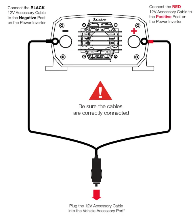
- Connect the RED (+) 12V Accessory Cable ring to the RED (+) inverter terminal.
- Screw the thumb cap back on the RED (+) inverter terminal.
- Connect the BLACK (-) 12V Accessory Cable ring to the BLACK (-) inverter terminal.
- Screw the thumb cap back on the BLACK (-) inverter terminal.
- Make sure the inverter is in the OFF position “O”.
- Plug the 12V Accessory Cable into vehicle accessory port*.
- When turning your inverter ON, place the power switch into the ON or “-” position by pressing the left side of the switch. When turning your inverter OFF, place the power switch into the OFF or “O” position by pressing the right side of the Power Switch.
*The 12V Accessory Cable can support on average up to 120 Watts. Do not overload. Please refer to your vehicle manual for the maximum load your vehicle’s accessory port can handle
CAUTION: Do not connect the inverter and another AC source (such as a generator or utility power) to the AC wiring at the same time. The inverter will be damaged if its output is connected to AC voltage from another source. Damage can even occur if the inverter is switched off.CAUTION: Do not connect the inverter to an AC branch circuit that has high-power consumption loads.It will not operate electric heaters, air conditioners, stoves, and other electrical appliances that consume more than 500 watts.CAUTION: Loose connectors result in excessive voltage drop and may cause overheated wires and melted insulation.CAUTION: Reverse polarity connections (positive to negative) will blow internal fuses in the inverter and may permanently damage the unit. Such damage is not covered by the warranty.CAUTION: We recommend the main fuse in the battery’s positive cable to protect against DC wiring short circuits (external to the inverter). The fuse should be as close to the battery as possible. We recommend a 60 Amp ANL fuse or equivalent. The specific fuse ampere rating should be sized to allow the operation of all your DC-powered equipment.CAUTION: Remove any jewelry (watch, ring, etc.). Be careful not to short circuit the battery with any metallic object (wrench, etc.).CAUTION: Electrical installations must meet local and national wiring codes, and should be performed by a qualified electrician.WARNING: If you are making a permanent AC connection to the inverter, make sure that the AC wiring steps are performed before any DC wiring is done. (DC hook-up energizes internal components, regardless of the position of the On/Off Switch). Working on AC connections in such a circumstance may result in an electric shock.WARNING: 115 volt AC power is potentially lethal. Do not work on AC wiring when it is connected to the inverter (even if it is switched off) unless the DC power source is physically disconnected from the inverter. Also, do not work on AC wiring if it is connected to another AC power source such as a generator or the utility line.WARNING: You may observe a spark when making the connection because the current can flow to charge the capacitors in the inverter. Do not make this connection in the presence of flammable fumes. Explosion or fire may result. Thoroughly ventilate the battery compartment before making this connection.
TURNING YOUR POWER INVERTER ON AND OFF
Be sure to have your power inverter properly installed before attempting to turn the unit on (see installation beginning on page 10)To turn the power inverter on:
- If a DC power supply is being used as the power source, switch it on.
- On the Output End, press the Power Button to on.
The power inverter is now ready to deliver AC power to your loads. If several loads are to be operated by the inverter, turn them on separately, after the inverter has been turned on. This will ensure that the inverter does not have to deliver the starting currents required for all the loads at once.
NOTE: The Power Button turns the control circuit in the inverter on and off. It does not disconnect power from the inverter.When the button is in the off position, the inverter draws no current from the battery. When it’s in the on position, but no power is being supplied to a load, the inverter draws less than 600 milliamperes from the battery. This is a low current draw. It would take more than a week to discharge a 100 ampere-hour battery at this rate depending on the age of the battery.
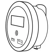
COBRA REMOTE ON/OFF CONTROLLER WITH FAST CHARGE USB
Your Cobra POWER inverter is equipped with an RJ-45 jack labeled “REMOTE” for compatibility with the Cobra Remote On/Off Controller with Fast Charge USB* to allow you to conveniently turn the inverter ON and OFF from anywhere inside your vehicle as well fast charge your devices at the same time. Perfect for use while driving, traveling, camping or tailgating when your inverter is out of reach. (4) mounting options allow you to install it permanently, use it while driving in a cup holder or clip it to the back of a seat or a place inside your vehicle.
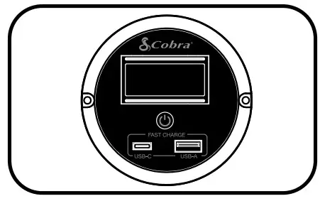
*Sold Separately. Can be purchased on www.Cobra.com
OPERATING INDICATORS
Indicators on the power inverter show the unit’s power status and alarms for conditions that could cause it to shut down. The power and protection indicator includes a dual color green and red light, and an alarm.Green LightPower on – The green light should remain on steady.Red Light and/or AlarmCurrent overload – The red light will blink continuously, then the inverter will shut down. The inverter will continue to check for appropriate current levels while trying to restart the load.DC input voltage overload – The red light will turn on and the inverter will shut down. The inverter will continue to check for appropriate voltage levels while trying to restart the load.DC input voltage shortage – As a warning that the voltage is getting low, the internal alarm will sound. When the voltage is too low, the inverter will shut down and the light will turn red. The inverter will continue to check for appropriate voltage levels while trying to restart the load.Temperature overload – The red light will blink, then the inverter will shut down. The inverter will continue to check for appropriate temperature levels while trying to restart the load.NOTE: A momentary sound of the internal alarm and/or flash of the red light is normal at startup.
OPERATING LIMITS
Power OutputThe inverter can deliver 500 watts for about 60 minutes. The inverter must cool for 15 minutes before it can resume operation at 500 watts. Note: The wattage rating applies to resistive loads.The inverter will operate most AC loads within its power rating. Some induction motors used in freezers, pumps, and other motor-operated equipment require very high surge currents to start. The inverter may not be able to start some of these motors even though their rated current draw is within the inverter’s limits. The inverter will normally start single-phase induction motors rated at one-half HP or less.Input VoltageThe inverter will operate from an input voltage ranging from 10 volts to 15 volts. Optimum performance will occur when the voltage is between 12 volts and 14 volts. If the voltage drops below 10.5V+/-0.3V, an audible low battery warning will sound. The inverter will shut down if the input voltage drops below 9.5V+/-0.3V. This protects the battery from being over-discharged. It will restart when the input voltage exceeds 12V+/-0.3V.The inverter will also shut down if the input voltage exceeds change to 15.5V+/-0.5V. This protects the inverter against excessive input voltage. Although the inverter has protection against over-voltage, it may still be damaged if the input voltage were to exceed 16 volts.
TROUBLESHOOTING GUIDE
| Problem/Symptom | Possible Causes | Solution |
| Low output voltage | Overload | Reduce the load. |
| No output voltage | Low input voltage | Recharge battery. Check connections and cable. |
| No output voltage after prolonged use | Thermal shutdown | Allow the inverter to cool off.Reduce load, continuous operation input current required.Improve ventilation; make sure ventilation openings in the inverter are not obstructed.Reduce ambient temperature. |
| No output voltage, “Protect” indicator lighted | High input voltage | Make sure the inverter is connected to a 12V battery.Check regulation or charging system. |
| No output voltage | Short circuit | Check a load for proper operation. |
| No output voltage | Inverter switched offNo power to inverter Reverse DC polarity | Turn inverter on.Check to wire to the inverter.Observe correct polarity. |
| Low battery alarm on all the time | Poor DC wiringPoor battery condition | Check connections.Make sure the battery is fully charged. |
SPECIFICATIONS
| Specifications: | POWER 500W |
| Model | CPI500W |
| Input | 13.0V DC |
| Output | 115V AC, 60Hz, 4.3A, 500W |
| Output Waveform | Modified Sine Wave (MSW) |
| Continuous Power | 500 Watt |
| Peak Power | 1000 Watt |
| Efficiency | 90% |
| No Load Draw | < .6A |
| Low Battery Alarm | 10.5V DC |
| Low Battery Shutdown | 9.5V DC |
| USB-A Output Port | 5V/3.0A, 9V/1.67A Fast Charge |
| USB-C Output Port | 5V/3.0A, 9V/1.67A Fast Charge |
| AC Output Socket | 2 GFCI Protected AC Outputs |
| Protection | Overload, Over Temperature, Short Circuit, Reverse Polarity, Over/Under Voltage and GFCI |
| Operating Temperature | -10°C/14°F – 40°C/104°F |
| Storage Temperature | -40°C/-40°F – 65°C/149°F |
| Power Cable Length: | 16″ #10 AWG (1) Red, (1) Black |
| CIA Cable Length: | 16″ |
| Compatible with Cobra Remote LCD (SIM CPIALCDG1) | Yes |
| Dimensions | 7.01″x5.39″x2.83″ |
| Net Weight | 1.41 lbs |
report this adSpecifications are subject to change without notice.
WARRANTY & TRADEMARK ACKNOWLEDGEMENT
Limited Two-Year WarrantyFor Products Purchased in the U.S.A.Cobra Electronics Corporation warrants that its Cobra power inverter, and the component parts thereof, will be free of defects in workmanship and materials for a period of two years from the date of first consumer purchase. This warranty may be enforced by the first consumer purchaser, provided that the product is utilized within the U.S.A.Cobra will, without charge, repair or replace, at its option, defective power inverters, products or component parts upon delivery to the Cobra Factory Service department, accompanied by proof of the date of first consumer purchase, such as a duplicated copy of a sales receipt.You must pay any initial shipping charges required to ship the product for warranty service, but the return charges will be at Cobra’s expense if the product is repaired or replaced under warranty. This warranty gives you specific legal rights, and you may also have other rights which may vary from state to state.Exclusions: This limited warranty does not apply:
- To any product damaged by accident.
- In the event of misuse or abuse of the product or as a result of unauthorized alterations or repairs.
- If the serial number has been altered, defaced, or removed.
- If the owner of the product resides outside the U.S.A.
All implied warranties, including warranties of merchantability and fitness for a particular purpose, are limited in duration to the length of this warranty. Cobra shall not be liable for any incidental, consequential or other damages; including, without limitation, to damages resulting from loss of use or cost of installation.Some states do not allow limitations on how long an implied warranty lasts and/or do not allow the exclusion or limitation of incidental or consequential damages, so the above limitations may not apply to you.For Products Purchased outside the U.S.A.Please contact your local dealer for warranty information.Trademark AcknowledgementCobra®, Nothing Comes Close to a Cobra®, Pentagon Protection®, and the snake design are registered trademarks of Cobra Electronics Corporation, USA. Cobra Electronics Corporation™ is a trademark of Cobra Electronics Corporation, USA.
MAINTENANCE & PRODUCT SERVICE
MaintenanceVery little maintenance is required to keep the inverter operating properly. The exterior of the unit should be cleaned periodically with a damp cloth to prevent the accumulation of dust and dirt. At the same time, tighten the screws on the DC input terminals. Be sure vents and fans are free of dust or debris.Product ServiceFor any questions about operating or installing this new Cobra product, please go to www.cobra.com
References
[xyz-ips snippet=”download-snippet”]