
Commercial Electric 5 in & 6 in LED Color Changing Recessed Trim User Guide
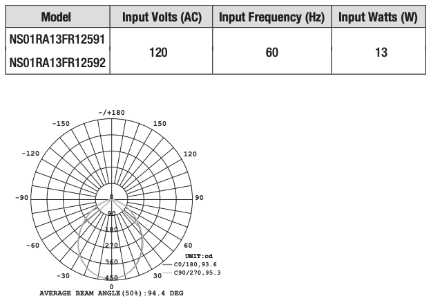
Item # 1004 399 132Model # NS01RA13FR12591Item # 1004 399 313Model # NS01RA13FR12592
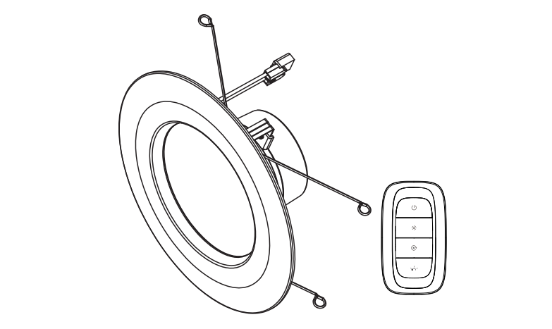
5 in & 6 in LED Color Changing Recessed Trim with Smart Light Switch
Questions, problems, missing parts? Before returning to the store, call Commercial Electric Customer Service8 a.m. – 7 p.m., EST, Monday – Friday9 a.m. – 6 p.m., EST, Saturday
1-877-527-0313
HOMEDEPOT.COM
THANK YOUWe appreciate the trust and confidence you have placed in Commercial Electric through the purchase of this LED light. We strive to continually create quality products designed to enhance your home. Visit us online to see our full line of products available for your home improvement needs. Thank you for choosing Commercial Electric!
Safety Information
![]() WARNING: Carefully read and understand the information given in this manual before beginning the assembly and installation. Failure to do so could lead to electric shock, fire, or other injuries which could be hazardous or even fatal.
WARNING: Carefully read and understand the information given in this manual before beginning the assembly and installation. Failure to do so could lead to electric shock, fire, or other injuries which could be hazardous or even fatal.
![]() WARNING: Ensure the electricity to the wires you are working on is shut off. Either remove the fuse or turn off the circuit breaker.
WARNING: Ensure the electricity to the wires you are working on is shut off. Either remove the fuse or turn off the circuit breaker.
![]() WARNING: Risk of fire or electric shock. Installation of this LED Retrofit Kit assembly requires a person familiar with the construction and operation of the light fixture’s/luminaire’s electrical system and the hazard involved. If not qualified, do not attempt installation. Contact a qualified electrician.
WARNING: Risk of fire or electric shock. Installation of this LED Retrofit Kit assembly requires a person familiar with the construction and operation of the light fixture’s/luminaire’s electrical system and the hazard involved. If not qualified, do not attempt installation. Contact a qualified electrician.
![]() WARNING: Install this kit only in luminaires (light fixtures) that have the construction features and dimensions shown in the photographs and/or drawings included in these installation instructions, and where the input rating of the retrofit kit does not exceed the input rating of the luminaire.
WARNING: Install this kit only in luminaires (light fixtures) that have the construction features and dimensions shown in the photographs and/or drawings included in these installation instructions, and where the input rating of the retrofit kit does not exceed the input rating of the luminaire.
![]() WARNING: Do not make or alter any open holes in an enclosure of wiring or electrical components during kit installation.
WARNING: Do not make or alter any open holes in an enclosure of wiring or electrical components during kit installation.
![]() WARNING: To prevent wiring damage or abrasion, DO NOT expose the wiring to sheet metal edges or other sharp objects.
WARNING: To prevent wiring damage or abrasion, DO NOT expose the wiring to sheet metal edges or other sharp objects.
![]() WARNING: Not intended for use with emergency exit fixtures or emergency exit lights. Suitable for wet locations.
WARNING: Not intended for use with emergency exit fixtures or emergency exit lights. Suitable for wet locations.
![]() WARNING: Used batteries should be disposed of at an appropriate recycling center. Do not discard with normal housedhold trash. DO NOT BURN.
WARNING: Used batteries should be disposed of at an appropriate recycling center. Do not discard with normal housedhold trash. DO NOT BURN.
![]() WARNING:
WARNING:
- Only use the control provided with or specified by these instructions to control this lamp.
- This lamp will not be operate properly when connected to a standard (incandescent) dimmer or dimming control.
![]() CAUTION: Any changes or modifications not expressly approved by the party responsible for compliance could void the user’s authority to operate the equipment.
CAUTION: Any changes or modifications not expressly approved by the party responsible for compliance could void the user’s authority to operate the equipment.
![]() CAUTION: Risk of electrical shock. Do not open. There are no user serviceable parts inside. Turn the power off before inspection, installation, or removal. The lamp is suitable for use in wet locations. Use only on 120 VAC, 60 Hz circuits.
CAUTION: Risk of electrical shock. Do not open. There are no user serviceable parts inside. Turn the power off before inspection, installation, or removal. The lamp is suitable for use in wet locations. Use only on 120 VAC, 60 Hz circuits.
NOTICE: Each light shall be installed only in its intended manner and orientation. Not all existing recessed cans that meet these requirements will be compatible with Commercial Electric recessed LED Trim. To ensure compatibility, a test installation should be conducted. The minimum starting temperature is -4 °F.
NOTICE: This device complies with part 15 of the FCC rules. Operation is subject to the following two conditions:
- This device may not cause harmful interference, and
- This device must accept any interference received, including interference that may cause undesired operation.
This equipment has been tested and found to comply with the limits for a Class B digital device, pursuant to Part 15 of the FCC Rules.These limits are designed to provide reasonable protection against harmful interference in a residential installation.This equipment generates, uses and can radiate radio frequency energy and, if not installed and used in accordance with the instructions, may cause harmful interference to radio communications. However, there is no guarantee that interference will not occur in a particular installation. If this equipment does cause harmful interference to radio or television reception, which can be determined by turning the equipment off and on, the user is encouraged to try to correct the interference by one or more of the following measures:
- Reorient or relocate the receiving antenna.
- Increase the separation between the equipment and the receiver.
- Connect the equipment into an outlet on a circuit different from that to which the receiver is connected.
- Consult the dealer or an experienced radio/TV technician for help.
Zigbee
Wireless Protocol: Zigbee 3.0. This device is fully Zigbee 3.0 certied.

Warranty
FIVE-YEAR LIMITED WARRANTY
The manufacturer warrants this lighting fixture to be free from defects in materials and workmanship for a period of five (5) years from date of purchase. This warranty applies only to the original consumer purchaser and only to products used in normal use and service. If this product is found to be defective, the manufacturer’s only obligation, and your exclusive remedy, is the repair or replacement of the product at the manufacturer’s discretion, provided that the product has not been damaged through misuse, abuse, accident, modifications, alterations, neglect, or mishandling.
WHAT IS NOT COVERED
This warranty shall not apply to any product that is found to have been improperly installed, set-up, or used in any way not in accordance with the instructions supplied with the product. This warranty shall not apply to a failure of the product as a result of an accident, misuse, abuse, negligence, alteration, faulty installation, or any other failure not relating to faulty material or workmanship. This warranty shall not apply to the finish on any portion of the product, such as surface and/or weathering, as this is considered normal wear and tear.
The manufacturer does not warrant and specifically disclaims any warranty, whether express or implied, of fitness for a particular purpose, other than the warranty contained herein. The manufacturer specifically disclaims any liability and shall not be liable for any consequential or incidental loss or damage, including but not limited to any labor / expense costs involved in the replacement or repair of said product.
Contact the Customer Service Team at 1-877-527-0313 or visit www.HomeDepot.com
Pre-Installation
PLANNING INSTALLATION
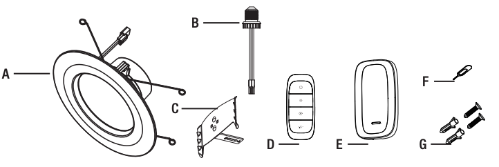
Before beginning assembly, installation or operation of product, make sure all parts are present. Compare parts with the package contents list. If any part is missing or damaged, do not attempt to assemble, install or operate the product. Contact customer service for replacement parts.
![]() WARNING: Shut off the power at the circuit breaker or fuse panel before removing the old fixture.
WARNING: Shut off the power at the circuit breaker or fuse panel before removing the old fixture.
![]() NOTE: Keep your receipt and these instructions for proof of purchase.
NOTE: Keep your receipt and these instructions for proof of purchase.
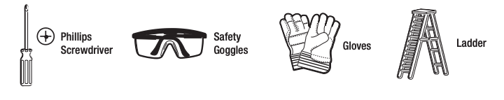
TOOLS REQUIRED
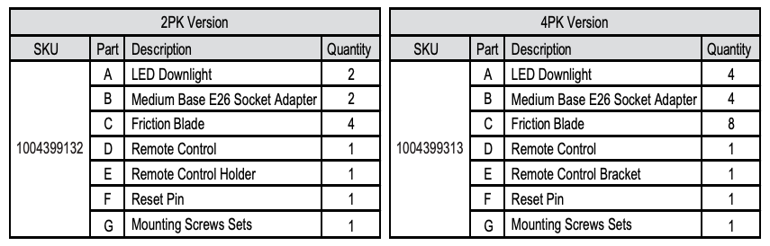
PACKAGE CONTENTS
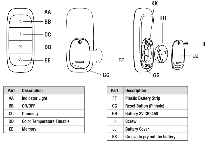
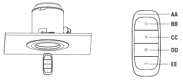
REMOTE CONTROL INTRODUCTION
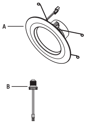
LED Downlight Installation
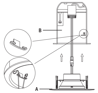
- Preparing the LED Downlight
- Remove the fixture (A & B) from the packaging.

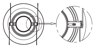
- The factory setting of the torsion spring clips is for a 6 in. housing.
- If using a 5 in. housing, loosen the screws on the torsion spring and slide the brackets outward. Re-tighten the screws to secure the torsion spring in place.
- Remove the fixture (A & B) from the packaging.
- Preparing the Installation Location and Compatible Housing
- Remove the existing trim and bulb from the housing, revealing the existing socket.
- Locate the socket in your existing recessed housing and remove any screws that prevent the socket bracket from being removed. NOTE: Change the torsion springs into friction blades if necessary before screwing the medium base (E26) socket adapter (B) into the socket in the recessed housing.
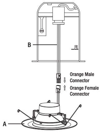
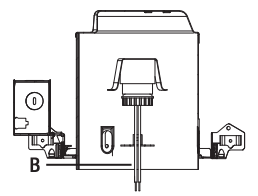
- Connecting the Socket Adapter
- Screw the medium base (E26) socket adapter (B) into the socket in the recessed housing.
- Screw the medium base (E26) socket adapter (B) into the socket in the recessed housing.
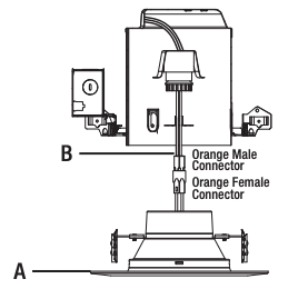
- Connecting the Cables
- Insert the orange female connector of the LED downlight (A) into the orange male connector on the socket adapter (B) screwed into the compatible housing.
- Insert the orange female connector of the LED downlight (A) into the orange male connector on the socket adapter (B) screwed into the compatible housing.
- Finishing the Installation
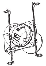
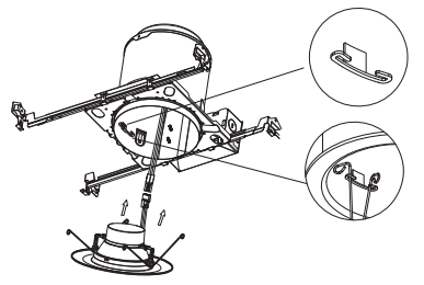
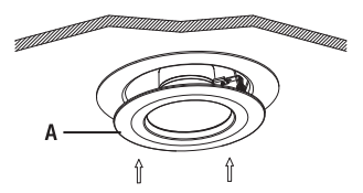
- Squeeze both torsion spring arms together and insert into the torsion spring slots of the can. Tuck all wires into the can and carefully push the LED downlight (A) into the can.
- Squeeze both torsion spring arms together and insert into the torsion spring slots of the can. Tuck all wires into the can and carefully push the LED downlight (A) into the can.


Installation Using Shallow Housings
![]() NOTE: Before beginning assembly, check for a compatible shallow can first.
NOTE: Before beginning assembly, check for a compatible shallow can first.
- Preparing the Installation Location and Shallow Housing
- Remove the existing trim and bulb from the housing.
- Remove the existing trim and bulb from the housing.
- Adjusting Shallow Housing
- Unscrew the wing nut inside the housing to detach the socket bracket from the can.
- Disengage the socket from the socket bracket.
- Connecting the Socket Adapter
- Screw the medium base (E26) socket adapter (B) into the socket in the recessed housing.
- Screw the medium base (E26) socket adapter (B) into the socket in the recessed housing.
- Finishing the Installation
- Insert the orange female connector on the LED downlight (A) into the orange male connector on the socket adapter (B) screwed into the compatible housing.
- Push the downlight (A) into the housing and insert the friction blades into the slots inside the housing. Tuck all of the wires into the housing and carefully push the downlight (A) into the housing.

Installation Using Non-Edison Base Socket LED Housings
- Installing the Downlight
- Insert the orange female connector on the LED downlight into the orange male connector on the socket adapter screwed into the compatible housing. Tilt the downlight while inserting the torsion springs into the brackets on the housing.
- Insert the orange female connector on the LED downlight into the orange male connector on the socket adapter screwed into the compatible housing. Tilt the downlight while inserting the torsion springs into the brackets on the housing.
- Finishing the Installation
- Tuck all of the wires into the housing and carefully push the downlight into the housing.
- Tuck all of the wires into the housing and carefully push the downlight into the housing.
Remote Control Bracket Installation
Decide upon your placement position and attach the remote control bracket with either mounting screws sets or double-sided adhesive tape.
- Using Mounting Screws Sets
- Insert flat blade screwdriver into grove (MM) to separate two parts of the bracket.Screw in the hole to fix the the back side on the wall or other firm surface demanding the thickness more than 1 inch. Two magnets (NN) are used to magnetize the remote control as below.
- Insert flat blade screwdriver into grove (MM) to separate two parts of the bracket.Screw in the hole to fix the the back side on the wall or other firm surface demanding the thickness more than 1 inch. Two magnets (NN) are used to magnetize the remote control as below.
- Using Double-Sided Adhesive Tape
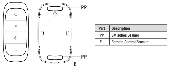
- Peel off the adhesive liner (PP) and attach the bracket (E) to the wall or other firm surface as you like.
- Peel off the adhesive liner (PP) and attach the bracket (E) to the wall or other firm surface as you like.

![]() NOTE: To avoid radio signal interference, do not install the remote bracket outdoors, near large metal objects and mirrors.
NOTE: To avoid radio signal interference, do not install the remote bracket outdoors, near large metal objects and mirrors.
Operation
Prepare the Remote Control
![]() NOTE: Battery will weaken with age and should be replaced before leaking takes place as this will damage the remote control. Dispose of used batteries properly and keep them out of the reach of the children.
NOTE: Battery will weaken with age and should be replaced before leaking takes place as this will damage the remote control. Dispose of used batteries properly and keep them out of the reach of the children.
Remove the plastic battery strip (FF) beneath the battery covering (JJ).The remote control and downlights in the pack are paired at the factory.
1. Operating the Downlight with the Remote Control
 ON/OFF
- Press the ON/OFF button (BB) to turn the light ON or OFF.
Dimming
- Press the dimming button (CC) to change the brightness from 10%-100%.
- There are two ways to change the brightness with the dimming button (CC):
- Short presses on the button change the brightness in a step manner.
- Holding down the button continuously changes the brightness with a smooth transition.
CCT Tunable
- Press the CCT Tunable button (DD) to change the color temperature from 2700K to 5000K.
- There are two ways to change the CCT with the CCT Tunable button (DD):
- Short presses on the button change the color temperature incrementally.
- Holding down the button continuously changes the color temperature with a smooth transition.
Memory
- Three preferred settings can be stored by using the memory function.
- To change the three default settings, change the downlight to the preferred dim setting and CCT, then hold down the memory button (EE) for 3 seconds. The indicator light (AA) on the remote will blink once, indicating that the settings have been stored into memory.
- After 3 settings have been stored, the next setting will replace the first stored setting.
- Press the memory button (EE) to execute the memory function.
![]() NOTE: The new mode will replace the last setting you executed, as the remote control can only keep three modes at most in its memory.
NOTE: The new mode will replace the last setting you executed, as the remote control can only keep three modes at most in its memory.
If additional downlights are needed to be paired with a remote control not purchased in its pack, before operation, proceed to Step 2 to unpair the downlight and Step 3 to pair with the downlight with the preferred remote.
 2. Unpair the Downlight
Position the remote control (E) within 2 inches of the downlight.
- To unpair the downlight with the remote, hold down the ON/OFF button (BB) and the CCT tunable button (DD) at the same time for 3 seconds.
- The indicator light (AA) will flash as it attempts to detect the downlight.
- Once detected, the indicator light (AA) will flash rapidly indicating the unpairing process is underway.
- The downlight will blink three times indicating it is unpaired.
- To reset the downlight (A), flip the power switch off and on once.
![]() NOTE: Only one downlight will be unpaired at a time. To unpair all the downlights simultaneously, reset all the downlights and remote control by following the instructions in the factory default section of the instructions.
NOTE: Only one downlight will be unpaired at a time. To unpair all the downlights simultaneously, reset all the downlights and remote control by following the instructions in the factory default section of the instructions.
3. Linking with the Remote Control
![]() NOTE: After removing the Plastic Battery Strip(FF), indicator Light (AA) will begin to blink indicating the power is on.
NOTE: After removing the Plastic Battery Strip(FF), indicator Light (AA) will begin to blink indicating the power is on.
To link the downlight to the remote control, follow the steps below called Touch-Link.
Touch-Link.
- Energize the power for the downlight and position the remote within 2 inches of the downlight. Press and hold the ON/OFF button ?? (BB) and Dimming button ?? (CC) at the same time for 3 seconds. The indicator light (AA) will begin to flash.
- The remote control (D) will start to search for the downlight (A). The indicator light (AA) will flash rapidly until the downlight (A) is detected.
- During the linking process, the downlight (A) will flash three times. The indicator light on the remote control (D) will remain on for 3 seconds. This indicates that the downlight (A) and remote control (D) have been successfully linked.
![]() NOTE:
NOTE:
- To link an additional downlight, follow the instructions above. The existing linked downlight may blink. If this occurs, press any button on the remote to stop the blinking. Then proceed with repeating the linking process.
- One remote control controls up to 20 downlights.
Factory Default
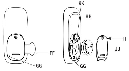
- To reset the remote control (D), insert the reset pin (F) into the reset button pin hole (GG) and hold for three seconds. This will reset the remote control without removing the battery cover (JJ).
- To reset the downlight (A), flip the power switch on and off six times.
Low Power Notification and Replacing the Battery
- The indicator light (AA) will blink twice fast indicating that the battery is low.
- To replace the battery, remove the battery cover (JJ) with a screwdriver.
- Use a flat head screwdriver to remove the battery (HH) and replace with a new 3V CR2450 battery (HH).
- Replace the battery cover (JJ) on the remote control (D) and tighten the screws (II).
Care & Cleaning
![]() CAUTION: Before attempting to clean the fixture, disconnect the power to the fixture by turning the breaker off or removing the fuse from the fuse box.
CAUTION: Before attempting to clean the fixture, disconnect the power to the fixture by turning the breaker off or removing the fuse from the fuse box.
- Clean the fixture with a soft, dry cloth.
- Do not use cleaners with chemicals, solvents, or harsh abrasives.
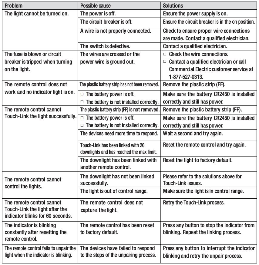
Troubleshooting
![]() WARNING: Before doing any work on the fixture, disconnect power to the light fixture by turning the breaker off or removing the fuse from the fuse box.
WARNING: Before doing any work on the fixture, disconnect power to the light fixture by turning the breaker off or removing the fuse from the fuse box.
Troubleshooting
Light Distribution
Compatibility
FOR USE WITH HOUSING MODELS:
COMMERCIAL ELECTRIC – HBR5ICAT, HBR5ICRAT, CAT7ICATA, CAT71CRM; CORDELIA – X5LICT, X5LICRAT, HBR7LICAT, HBR7LICRAT; CAPRI – CRI, CRR1; DMF – DH6ICATQ, DH6ICRATQ; ELCO – EL5ICA, EL5RICA; ELITE – B5, B5R, B5IC, B5RIC, B6IC, B6RIC; LITHONIA – L5, L5R, EL7ICA, EL7RICA, L7X, L7XR; NORA – NHIC-17QAT, NHRIC-17QAT; SEA GULL- RETROFIT TRIM 11018, 11028; THOMAS – PS1, PS1-RM; ALLPRO-APEI700AT; HALO-H5T, H5RT, H5ICT, H5RICAT, C7IC, C7ICR, C7ICA, C7ICRA, C7, C7R, C7S, HBR5000SIC; HALO – H7ICT, H7RICT, H7ICAT, H7RICAT, H7T, H7RT, H27ICT, H27T, H27RT, H550ICAT, H550RICAT, H750ICAT, H750RICAT.
FOR USE WITH SHALLOW HOUSINGS:
HALO-H27ICAT; LITHONIA-L7XP
FCC compliance information is listed as below:Responsible party: Leedarson America, Inc.Responsible party address: 300 Technology Court SE Suite 100, Smyrna, GA 30082Telephone number: (678) 293-8382
Questions, problems, missing parts? Before returning to the store,call Commercial Electric Customer Service8 a.m. – 7 p.m., EST, Monday – Friday9 a.m. – 6 p.m., EST, Saturday
1-877-527-0313
HOMEDEPOT.COM
Retain this manual for future use.
References
[xyz-ips snippet=”download-snippet”]