Quick Install GuideWAP-5903 AC1200 Dual Band WiFi Mesh-Enhanced Extender
An Understanding the WAP-5903 WiFi Mesh-Enhanced Extender
| LED Color | LED Status | Description |
| Green | On | The device is connected via Ethernet cable |
| Blinking | The mesh system is processing | |
| Blue | On | The device is connected to WiFi, and the connection quality is good |
| Blinking | The mesh system is processing | |
| Red | On | The device is connected to WiFi, and the connection quality is weak |
| Blinking | The mesh system is processing | |
| Green & Blue | Blinking | 1. The device is booting up and on stand-by
2. The device has lost the uplink connection |
| Green & Blue & Red | Blinking | 1. The device is upgrading the firmware
2. The device is under reset to default process |
| Port/Button Reset | Description | |
| Factory Reset Function: Press and hold this button for over 10 seconds | ||
| UPLINK | Connect this port to the LAN port of the Comtrend Gateway/modem/router. This port it used for Ethernet Pairing in a Comtrend WiFi mesh scenario. | |
| LAN | Optional: Use this port to connect an Internet-enabled device (e.g. laptop, set-top-box, etc.). |
Choose OneScenario I:Setup with a Comtrend Gateway that supports WifiXtend2.0™(Continue to Step B)Scenario II:Setup with either a non-Comtrend Gateway ora Comtrend Gateway that does not support WifiXtend2.0™(Continue to Step E)
WifiXtend2.0™ is Comtrend’s WiFi Mesh technology for enhanced whole-home WiFi coverage. The WAP-5903 and select Comtend Gateways support WifiXtend2.0™. When WifiXtend2.0™ technologies are being utilized, the WiFi network will automatically become a single network with one SSID and Password per band.
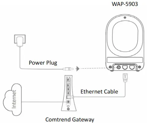
B Scenario I: Setting up the WiFi Mesh Extender with a Comtrend Gateway that Supports WifiXtend2.0™
- Use the included Ethernet cable to connect one end into the LAN port of the Comtrend Gateway that supports WifiXtend2.0™ and the other end into the UPLINK port of the WAP-5903.
- Power on the WAP-5903 by connecting one end of the Power Adapter into the Power Port of the WAP- 5903 and the other end into an outlet. The Ethernet Pairing will automatically start processing and the WAP-5903’s LED will begin blinking green.
- Wait until the WAP-5903’s LED is solid green. This means that the WAP-5903 is paired and grouped in the same WiFi mesh network as the Comtrend gateway.
- If you are setting up more than one WAP-5903, then please follow instructions 1-3 with the additional WAP5903 units.

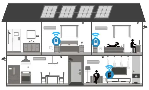
C Deploy the WiFi Mesh Extender
- After the WAP-5903 is paired, move it to the nearest outlet where additional WiFi coverage is needed. Onceit is plugged in, wait for the LED to light up solid blue, which means it is ready.
LED Description Solid Blue The WAP-5903 is placed in an ideal location and is receiving a good WiFi signal.
Solid Red The WAP-5903 is placed too far away from the Comtrend Gateway and is receiving a weak WiFi signal. Action Required: Move the WAP-5903 closer to the Comtrend Gateway. D The WiFi Mesh Network is Ready to Use!
- The WiFi mesh network is automatically using the original WiFi configuration on the Comtrend Gateway. If you would like to further change the network settings, then please refer to the Comtrend Gateway’s User Manual to make changes directly to the Gateway.
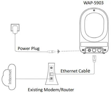
E Scenario II: Setting up the WiFi Mesh Extender with a Non-Comtrend Gateway/Comtrend Gateway that does not Support WifiXtend2.0™.Note: This scenario requires at least two WAP-5903 units to create a connection.
- Optional: Disable the WiFi on the non-Comtrend modem/router. This will help improve the performance of the WiFi Mesh Extender and avoid confusing the Internet-enabled devices.
- Use the included Ethernet cable to connect one end into the LAN port of the existing home modem/router and the other end into the UPLINK port of the first WAP5903.
- Power on this WAP-5903 by connecting one end of the Power Adapter into the Power Port of the WAP-5903 and the other end into an outlet.
F Setup the WiFi Network
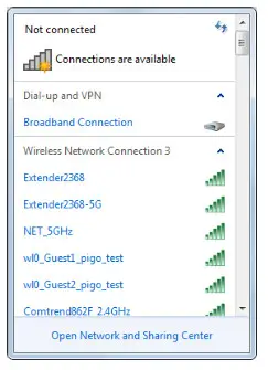
- ou can now use your computer’s wireless configuration utility to search for a Wireless Network name such as: Extender2368 or Extender2368-5G. (The default SSID of this extender device is ‘Extender2368’, and 2368 is for reference. It is thelast 4 digits of the device’s MAC number.)
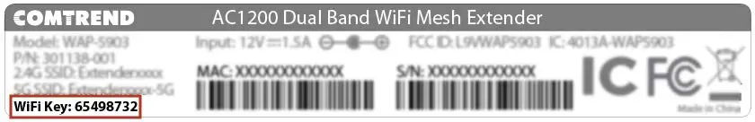
- When you are prompted to input the security key, the WiFi Key (password) can be found on the label at the back of the WAP-5903 device.
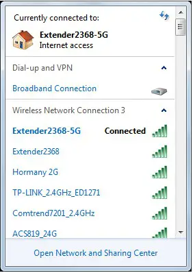
- Click the OK button to connect to the network.
- Open your web browser, and input ‘http://extender-setup/’ in the address bar.
- The system will prompt you to input the username and password. The default username is ‘root’ and the password is ‘12345’. Click the OK button to continue.
- After logging into the Web page, input the new SSID for both the 2.4GHz and 5GHz fields. The user can setup a new password by inputting it in both the Key fields. Click the Apply/Save button to complete setup.
- After applying the wireless setting the WAP-5903 will reboot. When the WAP-5903’s LED is solid green it means it is ready.
- You can now connect the additional WAP-5903. Power on the additional WAP-5903 by connecting one end of the Power Adapter into the Power Port of the WAP-5903 and the other end into an outlet. The Ethernet Pairing will automatically start processing and the WAP-5903’s LED will begin blinking green.
- Wait until the WAP-5903’s LED is solid green. This means that the WAP-5903 is paired and grouped in the same WiFi mesh network as the first WAP-5903.
- You can now move the additional WAP-5903 extender to the nearest outlet where more WiFi coverage is needed. Once plugged in, wait for the LED to light up solid blue, which means it is ready.
LED Description Solid Blue The WAP-5903 is placed in an ideal location and is receiving a good WiFi signal.
Solid Red The WAP-5903 is placed too far away from the Comtrend Gateway and is receiving a weak WiFi signal. Action Required: Move the WAP-5903 closer to the Comtrend Gateway.


Repeat steps 11-13 to add more WAP-5903 extenders to the mesh network.
G The WiFi Mesh Network is Ready to Use!
FOR MORE HELP: For instructions on advanced features, FAQ, etc., please visit our online Product Webpage.
For more information:YouTube: https://www.youtube.com/user/ComtrendConnectionFacebook: https://facebook.com/ComtrendWebsite: http://us.comtrend.com/Support: Visit our website or call (949) 753-9640
Federal Communication Commission Interference Statement
Radio
- This Transmitter must not be co-located or operating in conjunction with any other antenna or transmitter
- This equipment complies with FCC RF radiation exposure limits set forth for an uncontrolled environment. This equipment should be installed and operated with a minimum distance of 20 cm between the radiator and your body.
Safety
- For indoor users only
- Do NOT use near water
- Keep away from the fire
- For use in ventilated environment/space
- Do NOT open the casing
Power Specifications(Alimentation ) :Input: 12Vdc / 1.5A![]() Certification :FCC / IC standardPart 15B / ICES-003Part 15C / RSS-247( 2.4GHz )Part 15E / RSS-247( 5GHz )
Certification :FCC / IC standardPart 15B / ICES-003Part 15C / RSS-247( 2.4GHz )Part 15E / RSS-247( 5GHz )

Supplier’s Declaration of Conformity
WeCompany: Comtrend Corporation – North AmericaAddress: 530 Technology, Suite 100, Irvine CA 92618
Certify and declare under our responsibility that the following equipment:Product Name: AC1200 Dual Band WiFi Mesh ExtenderModel Name: WAP-5903Brand Name: COMTREND
Is tested with the declaration described above, and is in conformity with the relevant FCC (FedeCommunication Commission) standards, and technical specifications have been applied:
EMC:47 CFR FCC Rules and Regulations Part 15 Subpart B, Class B Digital Device

report this adNotes:15.19(a)(3) Regulations :This device complies with Part 15 of the FCC Rules. Operation is subject to the following twoconditions:(1) This device may not cause harmful interference, and(2) This device must accept any interference received, including interference that may cause undesired operation.
Class B :This equipment has been tested and found to comply with the limits for a Class B digital device, pursuant to part 15 of the FCC Rules. These limits are designed to provide reasonable protection against harmful interference in a residential installation. This equipment generates, uses, and can radiate radio frequency energy and, if not installed and used in accordance with the instructions, may cause harmful interference to radio communications. However, there is no guarantee that interference will not occur in a particular installation. If this equipment does cause harmful interference to radio or television reception, which can be determined by turning the equipment off and on, the user is encouraged to try to correct the interference by one or more ofthe following measures:— Reorient or relocate the receiving antenna.— Increase the separation between the equipment and receiver.— Connect the equipment into an outlet on a circuit different from that to which the receiver is connected.
[xyz-ips snippet=”download-snippet”]