
![]()
VEHICLE GPS TRACKERUser Manual (Version 1.7 )

This user manual has been specially designed to guide you through the functions and features of your GPS vehicle tracker.
Start Guide
1.1 Packaging
- GPS tracker
- Power cable
- Audio cable
- SOS cable
- MIC
- Relay
- User manual
1.2 Main Functions
- Real-time GPS+AGPS tracking
- Track by time interval or distance
- Remotely fuel/power cut-off
- Listen-in
- TTL
- Instant alerts for vibration, Overspeed, etc.
- External power supply cut-off alarm
- Two-way talk
- Door status detection
- Multiple analog & digital I/Os
- Battery charging protection
1.3Specifications
| Frequency | GSM 850/900/1800/1900MHz |
| GPRS | Class 12, TCP/IP |
| Operating Voltage | 9-36VDC / <300mA |
| Location Time | Cold Start: <35s |
| Hot Start : <2s | |
| Storage | 32Mb+32Mb |
| Battery | 450mAh |
| Location Accuracy | <10 meters |
| Operating Temperature | -20°C∼ +70°C |
| Dimension | 80.9 ( L ) x55.8 ( W ) x23.4 ( H ) mm |
| Weight | 95g |
My Device
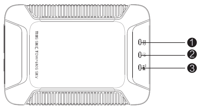
2.1 Appearance
 |
 |
|
2.2 LED indicators
| GPS LED Indicator – Blue | ||
| 0.1s ON & 0.1s OFF | Searching GPS signal | |
| Steady on | GPS is fixed | |
| OFF | Sleep or not work |
| GSM LED Indicator – Green | ||
| 0.1s ON & 0.1s OFF | GSM initializing | |
| 0.1s ON & 2s OFF | Receive GSM signal normally | |
| Steady on | Connected to GPRS network | |
| OFF | No GSM signal |
| Power Status – Red | ||
| 0.1s ON & 0.1s OFF | Low battery | |
| 2s ON & 2s OFF | Full charged | |
| 0.1s ON & 2s OFF | Normal operating | |
| Steady on | Device is charging | |
| OFF | Low battery/Power off |
| Flash in a loop | The device is in defense status |
Wire Connection
3.1 Wire Definition
| 14GND | 12ADC | 10SOS- | 8OUT2+ | 6IN1 |
| 15PW+ | 13ACC | 11SOS+ | 9Relay | 7OUT1- |
| 4 | 2 |
| TX | GND |
| 5 | 3 |
| RX | 5V_OUT |

| Line | Color | Description | Definition |
| 1 | MIC + SPK | 3.5mm | |
| 2 | GND | Ground | |
| 3 | 5VDC_OUT | Controllable | |
| 4 | TX | Transmit data | |
| 5 | RX | Receive data | |
| 6 | Green | IN1 | Configurable positive input/negative input |
| 7 | White & yellow | OUT 1 – | Negative output |
| 8 | White &red | OUT2+ | Controllable positive output (power voltage), ≥-500mA current |
| 9 | Yellow | Relay | Fuel/Power cutoff |
| 10 | Black | SOS- | SOS (Negative) |
| 11 | White | SOS+ | SOS(Positive) |
| 12 | Purple | ADC | Detect 0.3-30V voltage |
| 13 | Orange | ACC | ACC |
| 14 | Black | GND | Ground |
| 15 | Red | PW+ | Power: 9-36V |
3.2 Wiring diagramOptional
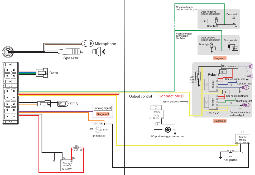
Notice: Purple line (ADC) of terminal connects to analog signals line, like voltage of the external device, analog temperature sensor, fuel sensor. The voltage detected by analog signal ranges from 0-30Vdc.
Wiring Instruction
- The standard power supply ranges from 9V to 36VDC. Please use the power cord manufactured by the original factory. Redline means positive side while the black line means negative side. During installation, the negative side should connect to the ground, do not connect with other ground wires at the same time.
- ACC line (orange) connects to the vehicle’s ACC switch, detecting ignition on and off.
- The device’s oil and electricity control line (yellow) connects to relay’s 86. (thin yellow line of relay socket)Relay wiring instructionRelay wiring way of oil pump open circuit: On each end of the wire is a thin white line (85) and a thin yellow line (86). A thin white line (85) connects to the positive side of the battery (12V) while a thin yellow line (86) connects to the device relay control. There is an oil pump in the vehicle. Cut off the positive line. The positive side of the oil pump connects to the close-end of the relay.(Thick green line 87a), and the other side connects to relay’s common(green thick 30).Notice12V relay is standard. The device is suitable for vehicles with 12V batteries. If the vehicle has a 24V battery, then a 24V relay is needed.
- To monitor analog signals, the purple line (ADC) of the extended port should be connected to the analog line.
- To check the status of the car door, a green line (IN1) should be connected to where between the door light and door switch (See the diagram).
- To find the car remotely, please connect the yellow line (OUT1) of the extended port to the external relay.
3.3 Device Installation
Note :The device should face up to the sky.Metal thermal barrier or heating layer of the windshield affects the signal. Please change Installation places to receive better signals.
Operation of device
Power on/ Power offPower on: Once you insert a valid SIM card and connect all the wires, turn on the device. Power LED will flash first. During the signal searching process, GSM LED and GPS(blue) LED will flash. Once Blue GPS LED keeps steadily ON, it means the device has been located and it starts to work.Power off: Just toggle off the power switch.Notice:When the device is connected with external power, please turn on the battery switch. The battery will then connect with the device circuits and its built-in battery will be charged. If the battery is OFF, the battery can’t be charged. The device will be power off if no external power supply.
Main Functions
5.1 SOSIn emergent cases, press SOS for 3 seconds to activate the SOS alarm. Then the device will send SOS SMS to preset SOS numbers and then dial the numbers in a loop 3 times until the call is picked up. Alarm messages will also send to the platform. (See command list 7-9)
5.2 Power cut-off alarmWhen the electricity supply of the device is cut off, It will activate the cut-off alarm.
5.3 Low battery alarmWhen the battery is low, the device will activate the low battery alarm. The device will send alerts through SMS and to the platform.
5.4 Vibration alarm (default OFF)When the vehicle vibrates several times, the vibration alarm will be triggered. If ignition keeps OFF for 3 minutes (ACC OFF), the device will send a vibration alarm message immediately. (See command list 713)
5.5 Voice monitoring
- When MIC is connected while the speaker is not, use pre-set SOS number to dial the device, after 10 seconds, the device enters into monitoring mode automatically. The caller can hear the voice inside the vehicle.
Notice
- Pre-set SOS number is necessary.The non-SOS numbers cannot activate this function.
- SIM card of the device must have caller ID service.
5.6 Two-way communication
To activate this function, ensure that both MIC and speaker are connected well.
Use pre-set SOS number to dial the device, after 10 seconds, the device enters into two-way talk mode.
5.7 Displacement alarm(default OFF)The device will send a movement alarm when the vehicle moves out the preset distance (when ACC is off and GPS is fixed).
5.8 Oil/Electricity cut-offWhen a vehicle is stolen, the oil/electricity cut-off command can be sent by platform, APP or SMS.
Notice
- Make sure ACC is correctly connected.
- When ACC is OFF, the command will be executed immediately.
- When ACC is ON, but GPS is not fixed, the command will be postponed.
- When ACC is ON, GPS is fixed, the command will be executed when the vehicle speed is less than 20km/h.
If you want to cut off/restore oil by SMS command, you have to set a center number firstly. Only the center number can send the cut-off/restore oil command to the device. (See command list 7-15)
Notice
- 0nly the SOS number can be used to set the center number.
- Only the SOS number can be used to delete the center number.
- There is only one center number that can be set.
5.9 Restore oil/electricityWhen an alarm is all clear, you can send a restore oil/electricity command by platform, APP, or SMS and restore vehicle power. (See command list 7-16)
5.10 Restart deviceIf GPRS Is abnormal (the device is offline), the user can send the SMS command RESET# to restart the device. The device will reboot after 20 seconds after receiving the command. (See command list 7-17)
5.11 Door detectionThe device is able to detect door status. It uploads car status to the platform and APP in a timely. Negative triggering is the default. When the car door’s status is negative triggering, there is no need to set. Instead, if car door status is positive triggering, the triggering way has to be modified. (Command: DOOR,1#). See 3.2 diagram- 1 for wiring way. (See command list 7-18)
NoticeNegative triggering (default): when the door is open, the signal level of the door is OV; when the door is closed, the signal level of the door is power voltage. Positive triggering: when the door is open, the signal level of the door is power voltage; when the door is closed, the signal level of the door is OV.
5.12 Analog signalThe device can measure the car battery’s voltage and upload it to the platform/APP in a fixed time based on your needs. Purple line (ADC) of device extended port can receive an analog signal, like voltage of the external device, analog temperature sensor, and fuel sensor. The voltage range of analog input is 0-30Vdc. See 3.2 diagram for wiring way. (See command list 7-19)
5.13 Lithium battery charging protectionBuilt-in battery won’t be charged when the temperature is over 50°C or less than -20°.As soon as the temperature is lower than 48°C or above -18°, battery charging will be restored.
5.14 Controllable outputThe device supports high/low-level output, which could be configured by commands based on needs.
6. Platform OperationGet registered on the designated service platform by an authorized dealer, then you can start the tracking service and settings.
6.1 APN & Server settingTo ensure normal network operation, please confirm your APN and server setting before login.In most countries, APN could be automatically adapted to local mobile operators. If not, please send an SMS to set the APN.If a username and password are required for APN, please add them to the command. (See command list 7-7)Confirm the server address and setting with distributors. If the server is incorrect, please send an SMS to change. (See command list 7-8)
6.2 Login service platformPlease login to the designated service platform to set and operate the device.6.3 Download APPPlease download and install the APP on the designated website, APP Store, or Google Play store.
Common Command-List
Edit SMS command in the right column to the device SIM number to achieve the respective function as below:
| 1 | Device status | STATUS# |
| 2 | Device coordinate | WHERE# |
| 3 | Location URL | URL# |
| 4 | Check version | VERSION# |
| 5 | Network setting | GPRSSET# |
| 6 | Check parameter | PARAM# |
| I- | APN setting | 1. APN,apnname#E.g:APN,internet#2. APN,apnname,user,pwd#E.g: APN,internet,CLIENTE,AMENA# |
| 8 | Server setting | SERVER,mode,domain/IP,port,0#E.g. SERVER,1,www.ydpatcom,8011,0#SERVER,0,211.154.135.113,8011,0# model means set with domain name mode 0 means set with Ip address |
| 9 | SOS setting | 1. Add SOS number:SOS,A,number 1,number 2,number 3#2. Delete subjected sequence of SOS number:SOS,D,number sequence 1,number sequence 2, number sequence 30 E.g. SOS,D,1,2,3#3. Delete the SOS number: SOS, D, phone number#4. Query SOS number: SOS# |
| 10 | GPS data upload interval interval | TIMER, T1, T2#T1=5^-18000 seconds; ACC ON upload interval; default value: 10T2=5^-18000 seconds: ACC OFF upload Interval: default value; 10(when GPS is not sleeping) |
| 11 | GPS data upload distance interval | DISTANCE,D#D=0. 50,-10000 meter ;Distance Interval ; default value : 300, unit : meter ; |
| 12 | Delayed defense setting | DEFENSE, A#A:1–60 minutes, set delayed defense, default value: 10 minutes |
| 13 | Vibration alarm (default OFF) | 1. SENALM, ON#2. SENALM, OFF# |
| 14 | Displacement alarm setting
(default OFF) |
1. MOVING,ON,R,M#R=100-1000; Displacement radius, unit: meterM=0-2; Alert way0:GPRS, 1:SMS+GPRS ;2: GPRS+SMS+CALLE.g. MOVING,ON,200,2#2. MOVING, OFF# |
| 15 | Set center number | Set center number :CENTER,A, mobile number#Delete center number: CENTER, D# |
| 16 | Power/oil control | RELAY, A#A=0/10= restore petrol; 1=cut off petrol Default value : 0E.g. RELAY,1# |
| 17 | Restart | RESET#Device restart 20 seconds after receiving this command |
| 18 | Car door negative! positive triggering setting | DOOR, A#A=0/1; 0 negative triggering, 1 positive triggering ;default: 0 |
| 19 | Analog upload setting | Upload analog data: ADT,ON,T#T: upload interval; scope: 5-3600(second) Turn off analog upload : ADT,OFF# ; default: OFF |
| 20 | Find car by triggering light and buzzer | FIND# |
Troubleshooting
If you are having trouble with your device, try these troubleshooting procedures before contacting a service professional.
| Problems | Causes | Solutions |
| Poor signal | The signal waves are unable to transmit when using the GPS tracker in the places that have poor signal reception, such as tall buildings or basements. | Using the GPS tracker in places that have good signal conditions. |
| Unable to boot | Low battery | Charge the device battery |
| Unable to connect to the network | Poor signal | Using the GPS tracker in the places that have the good signal conditions. |
| Unable to locate | Signal shielded or Poor signal | Change the installation place |
| No power off alarm | The built-In battery is off | Turn It on |
| Fail to start the car | Power cutoff / ACC abnormal | Restore power/Check ACC |
| Car stops driving | Abnormal power supply | Connect the device negative electrode to constant power |
| Offline/ Indicators off | Abnormal power supply/Indicators sleep | Check power supply/Press side key to activate indicators |
| No update of vehicle’s location | No GPS positioning | Test the device again/ Change Installation place |
Warranty instructions and service
- The warranty is valid only when the warranty card is properly completed and upon presentation of the proof of purchase consisting of original invoice indicating the date of purchase, model, and serial No.of the product. We reserve the right to refuse a warranty if this information has been removed or changed after the original purchase of the product from the dealer.
- Our obligations are limited to repair of the defect or replacement the defective part or at its discretion replacement of the product
- Warranty repairs must be carried out by our Authorized Service Warranty cover will be void, even if a repair has been attempted by any unauthorized service center.
- Repair or replacement under the terms of this warranty does not provide the right to extension or renewal of the warranty period.
- The warranty is not applicable to cases other than defects in material, design, and workmanship.
Maintenance Record
| Date | Serviced by |
| Product Model | |
| IMEI Number | |
| Fault Descriptions | |
| Comments |
FCC Radiation Exposure Statement:
Thetransmittermustnotbecolocatedoroperatedinconjunctionwithanyother antenna or transmitter.ThisequipmentcomplieswiththeFCCRFradiation exposure limits set forth forum controlled environment. This equipment should beinstalledandoperatedwithaminimumdistanceof20cmbetweentheradiator
Information to Users
According to the FCC Part15.19, 15.21, and 15.105 rules, for this EUT, the instru action soro operation manual furnished the user shall include the following or similar statement placed in a prominent location in the text of the manual:
FCC Warning
ThisdevicecomplieswithPart15oftheFCCRules.Operationissubjecttothefollowing two conditions: (1)Thisdevicemaynotcauseharmfulinterference, and(2)this device must accept any interference received, including interferon that may cause the desired operation.
NOTE1: ThisequipmenthasbeentestedandfoundtocomplywiththelimitsforaClassB digital device,pursuanttopart15oftheFCCRules.Theselimitsaredesignedto providereasonableprotectionagainstharmfulinterferenceinaresidential installation. This equipment generates, usesandcanradiateradio frequency energy and, ifnotinstalledandusedinaccordance with the instructions, may cause harm fulinterferencetoradiocommunications. However, the reisnoguaranteethat interferencewillnotoccurinaparticularinstalIation.Ifthisequipmentdoescause harmful interferencetoradioortelevisionreception, which can be determined by
-Reorientorrelocatethereceivingantenna.-Increasetheseparationbetweentheequipmentandreceiver.-Connecttheequipmentintoanoutletonacircuitdifferentfromthattowhichthe receiver is connected.-Consultthedealeroranexperiencedradio/TVtechnicianforhelp.
NOTE2: Anychangesormodificationstothisunitnotexpresslyapprovedbytheparty
[xyz-ips snippet=”download-snippet”]