CTSMC013.2Mercedes Benz Steering Wheel Control Interface
INSTRUCTION MANUAL
ABOUT THIS PRODUCT…
CTSMC013.2Mercedes Benz steering wheel control interfaces for Mercedes Benz vehicles with CAN-Bus.
- SWC Interface
- MOST Interface
- RCA Connectors (> Pre-Out on H/U)
- Power/Ground Connector (> Back of Display)
- CAN Connection (> Empty Slot Underneath Glovebox)
- ISO Connector (> H/U Female ISO)
- Flying Wires (Speed Pulse, Reverse, Parking Brake)
Product Contents– Interface– Harness– InstructionApplicationE-Class (W211) 2002 – 2009SLK (R171) 2004 – 2010CLS (W219) 2004 – 2010
For Fibre Amplified Vehicles CT27AA151 antenna an extension may be required for installation
Prior to installation
Read the manual prior to installation. Technical knowledge is necessary for installation. The place of installation must be free of moisture and away from heat sources. Please ensure you use the correct tools to avoid damage to the vehicle or product.Connects2 can not be held responsible for the installation of this product.
Technical Support
Connects2 wants to provide a fast and suitable resolution should you encounter any technical issues. With this in mind, when contacting Connects2, try to provide as much information as possible. This will speed up the process and help us to help you.
Please use our dedicated online technical support centre: support.connects2.com
Subscribe to our YouTube Channel for installation guides and tips… www.youtube.com/connects2
FITTING GUIDE
- Remove and disconnect the original head unit.
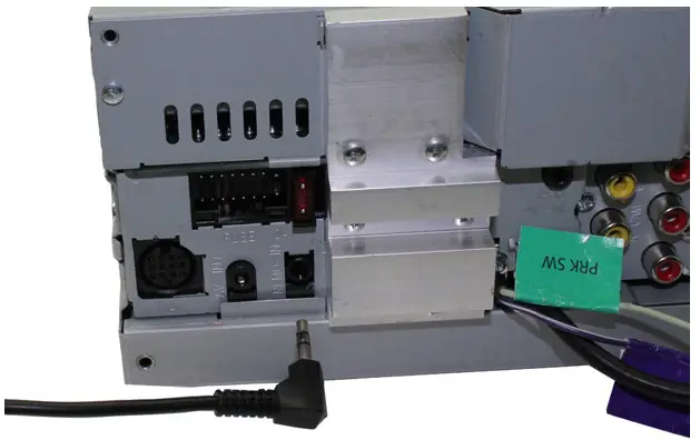
- Connect the 12-way Molex connector of the head unit patch lead (supplied separately) to the interface.

- Connect the opposite end of head unit patch leads to the head unit steering wheel control input on the back of the aftermarket head unit. This may be a 3.5mm jack plug or a wired input depending upon the head unit brand being fitted. Please see the head unit installation manual for further information on where to connect.Important Note: This step must be completed before connecting power to the interface. Failure to so may result in no steering wheel control function.
- Connect the 14-way Molex connector to the interface.
- Connect the male power/speaker ISO harness to the female power/speaker ISO harness from the aftermarket head unit.For aftermarket head units which do not have an ISO connector the interface uses the following wiring colours:
Wire Colour
Function
Yellow Permanent 12V Black Ground Red 12V Ignition Orange Illumination Blue Antenna Remote Pink Speed Pulse Green Park Brake Purple/White Reverse Purple Right Rear Speaker + Purple/Black Right, Rear Speaker – Green Left Rear Speaker + Green/Black Left Rear Speaker – Grey Right Front Speaker + Grey/Black Right, Front Speaker – White Left Front Speaker + White/Black _ Left Front Speaker – - Connect the Yellow/Black Fibre Amp retention connector to the power connector (previously removed from the back of the head unit)
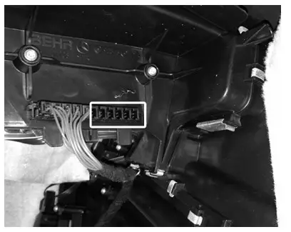
- Remove the kicker panel beneath the glove-box (pictured) and feed the Blue/White CAN wire behind the dashboard and out under the glovebox
- Plug Blue/White connector into a vacant slot in the CAN Hub (pictured)
- Connect the 8-Way connector to the MOST Interface
- Connect the White/Red RCA connectors to the pre-out at the back of the head unit
- Test head unit for correct operation and reinstall glovebox panel and dashboard.


STEERING WHEEL CONTROL FUNCTIONS
- Track +
- Track –
- Source
- Volume +
- Volume –
- Pick Up
- Hang Up
NOTES
References
[xyz-ips snippet=”download-snippet”]