CONNECTS2 CTSRN011.2 Steering Wheel Control Interface

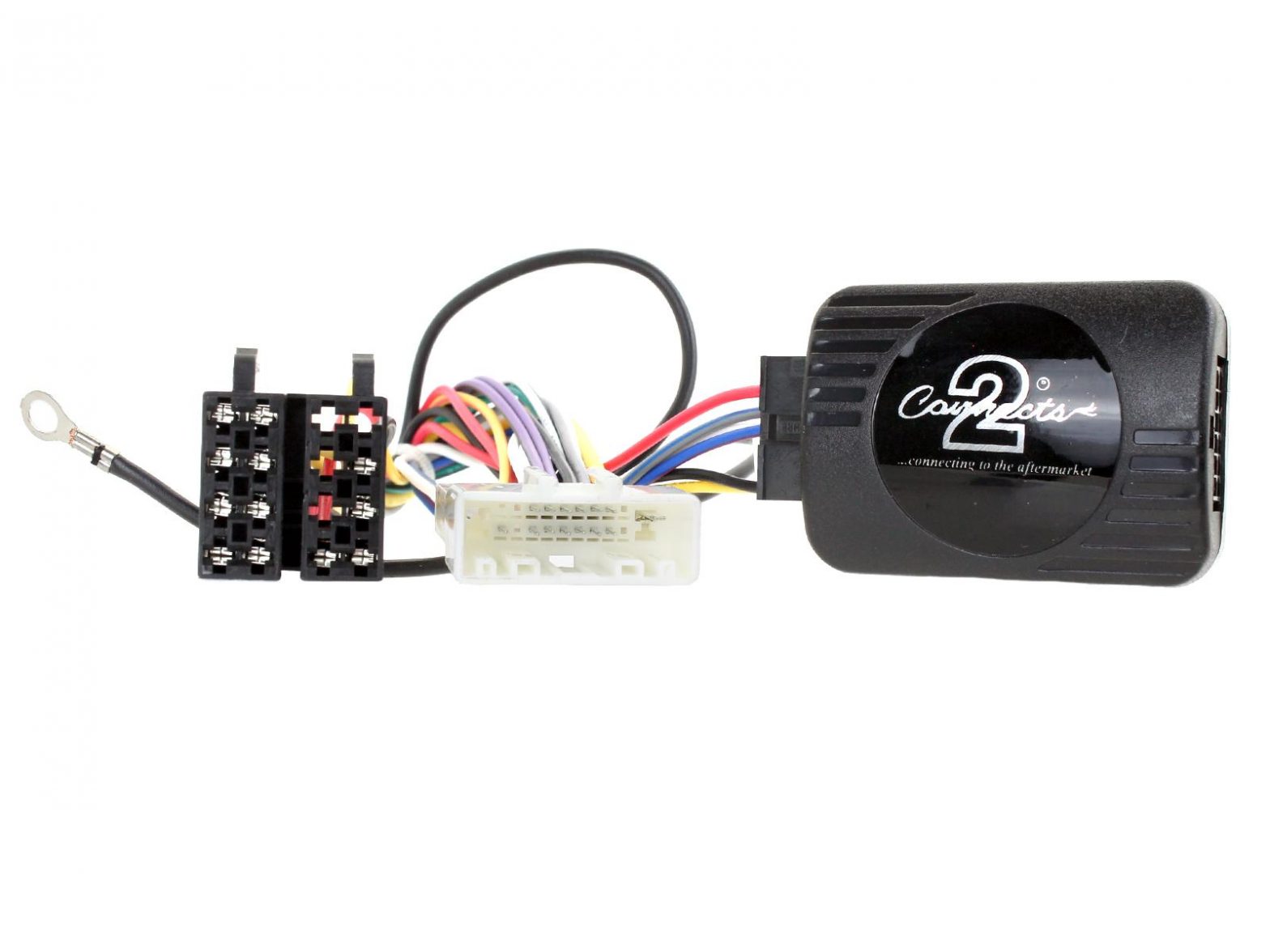
Contents (Left to Right):
- ISO Connector (16 Pin)
- Vehicle Specific Connector (32-pin)
- Vehicle Specific Connector (20-pin)
- Interface
FEATURES
- Retains Factory Steering Wheel Control Functionality
- Retains Phone Button Functionality (if vehicle is equipped)
- Updateable via USB (contact supplier for more information)
DISCLAIMERThe information provided in this document is subject to change without notice due to manufacturer changes and/or improvements to the product/s. This instruction manual is based on documented data and research. The manufacturer of this product cannot be held responsible for any changes made to the vehicle by the manufacturer or damages that may occur through the installation of this product in accordance with the steps outlined herein.
PRODUCT INFORMATION
CTSRN011.2The CTSRN011.2 is an Analogue steering wheel control interface that allows the installation of an aftermarket single or double stereo into select Renault vehicles. This interface and harness combination allows the retention of select steering wheel controls and phone button functionality (if applicable).
WIRING KEY
IN WIRING HARNESS
- Purple
- Purple/Black
- Green
- Green/Black
- Grey
- Grey/Black
- White
- White/Black
Right Rear Speaker +Right Rear Speaker –Left Rear Speaker +Left Rear Speaker –Right Front Speaker +Right Front Speaker –Left Front Speaker +Left Front Speaker –
STEERING WHEEL CONTROL FUNCTIONALITY
The following diagram, though based on careful research, is an example only. Individual steering wheel control configurations may differ.NB: steering wheel controls can be adjusted through the change of the Dipswitch within the interface box. This is dependent on the type of steering wheel layout the vehicle has. See information below before installation.
Config A.
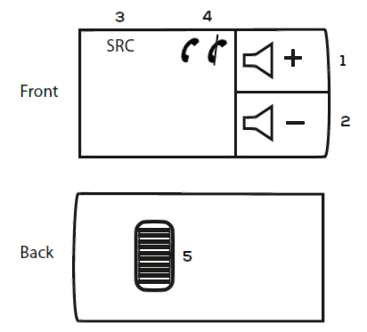
- Volume +
- Volume –
- Source
- SourcePick Up (Short Press) Hang Up (Long Press)
- Track + / Track –
Config B.
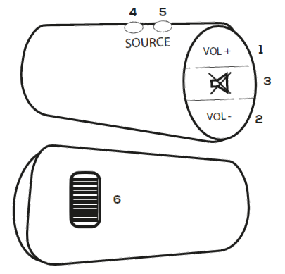
- Volume +
- Volume –
- Mute
- Source
- SourcePick Up (Short Press) Hang Up (Long Press)
- Track + /Track –
PRIOR TO INSTALLATION
Read the manual prior to installation. Technical knowledge is necessary for installation. The place of installation must be free of moisture and away from heat sources. Please ensure that the correct tools are using during the installation to avoid damage to the vehicle or product. Connects2 can not be held responsible for the installation of this product.
INSTALLATION GUIDE
Before installing the interface, the factory stereo must be removed and disconnected. To do this, please consult the vehicle owner’s manual/handbook or contact a fitting professional.A stereo connection (patch) lead is also required for the installation of this interface (supplied separately). Please ensure that you have the correct lead before proceeding. For universal patch leads, prepare the wiring loops in accordance with the instruction manual supplied with the product before installation.
- Connect the 12 Pin connector from the stereo connection (patch) lead to the interface box
- Connect the opposite end of the stereo connection (patch) lead to the steering wheel control input on the back of the aftermarket stereoNOTE: This may be a 3.5mm jack connector or a wired input depending on the brand of aftermarket stereo being fitted. Please consult the aftermarket stereo installation manual for further information on where to make the connectionIMPORTANT: THIS STEP MUST BE COMPLETED BEFORE CONNECTING POWER TO THE INTERFACE. FAILURE TO DO SO MAY RESULT IN A LACK OF FUNCTIONALITY AND THE NEED TO RE-INSTALL THE PRODUCT
- Connect the 14 Pin connector from the supplied wiring loom to the interface box
- Connect the male power/speaker ISO connector to the female power/speaker ISO connector from the aftermarket stereo.NOTE: For aftermarket stereos which do not have an ISO connector, please see “Wiring Key” on Pg.2 for information on which wires to connect. Some interfaces may also have additional ‘flying’ wires which can be connected to the vehicle to support various features ie. parking brake trigger, reverse gear and speed pulse. Details of these can be found under ‘Additional Connections’.
- Connect both the vehicle specific connector/s on the supplied harness to the corresponding connection from the vehicle.
- Test stereo and steering wheel control functionality for correct operation before reassembling the vehicle dashboard. If steering wheel control functions are unresponsive, please uninstall the interface and wiring and reinstall carefully in accordance with the above steps.
WIRING DIAGRAM

![]()
[xyz-ips snippet=”download-snippet”]