
![]()
Please read this guide carefully and retain for future use and maintenance.Installation and User Guide
SL Wireless Controller
- Getting to know your SL wireless controllerThe SL controller has 3 operating modes. It has to be set to the required mode prior to the installation by using the switches located at the back of the controller. These modes are:• Basic• Timer• Temperature ControlThere are 4 light indicators located around the button showing the status of the controller.
-
Pairing
If the controller is flashing red when powered this shows there is a fault with the unit and it should be replaced.In order to pair your heater with the controller you must:• Turn Heater ON• Within 20 seconds, hold the button on the controller until the orange segments are lighting up in a sequence.
-
Basic Mode
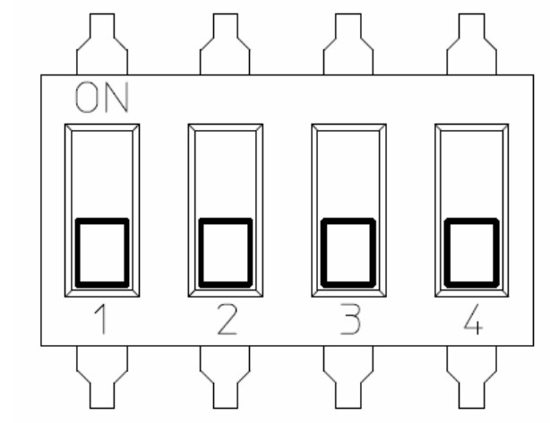
For basic mode, the switches are set as shown below.
 Controller functionality in basic mode:Press button to activate heating, press button again to set controller to stand-by.When heating is active, the 4 light indicators are green. After pressing the button, heating is set to stand-by; the indicators will change from green to red for 4 seconds and then go off.
 -
Timer Mode
For timer mode, the switches are set as shown below.
In timer mode, switch 3 or 4 must be in the ‘ON’ position. This mode allows for 3 different settings which will alter the time period for each segment.Switch 3 – Each time period represents 5 minutes.Switch 4 – Each time period represents 10 minutesSwitch 3 & 4 – Each time period represents 15 minutesController functionality in timer mode:In timer mode, the controller acts as a 4 stage run-back timer. When the controller is in stand-by mode and button is pressed, the first indicator segment will light up green, and heating is activated. When pressed again the second segment will light up and so on. Each segment is representing a time period that is selected when setting the switches.In the example below, the only switch in the ‘ON’ position would be number 3. The button would be pressed four times to activate four 15-minute segments resulting in the heater staying on for 1 hour. At the end of the last time period, the light indicators will be red for 4 seconds and then go off. The controller is now in standby mode. -
Temperature Control Mode
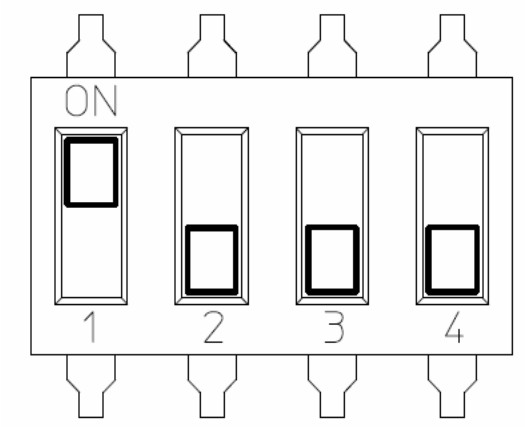
Temperature control for Comfort periodFor this mode, switches are set as shown below.
The temperature control feature will effectively maintain the set room temperature. The target temperature can be set using the variable resistor located at the back of the controller as shown below. The range is 15ºC – 35ºC. Once the room temperature reaches the set temperature, the indicators will change from green to orange. When the room temperature drops, heating will became active and the indicators will change to green.Temperature control for Setback periodFor this mode, the switches are set as shown below.In this mode, the controller will set heating active when the room temperature drops below the set temperature. This feature can be used for frost protection or in situations where a minimum room temperature must be maintained. The setback temperature can be set using the variable resistor mounted on the back of the unit as shown above. This can be set from 0ºC – 15ºC.If the heating is active in the setback mode, the indicators will illuminate red and green.Temperature control for comfort and setback periods can be used individually or together. This can also be used in conjunction with the timer mode options. -
External Input
The controller has an external input located on the back of the controller. The external input can be connected to any voltage free contacts, for example, timers or BMS.
If the external input is used and the contact is closed, the indicators will light up red and stay red. When the controller is in this function, none of the modes will work apart from setback. If the contact is open the controller will function as normal. -
Installation
The controller is designed to fit onto any deep single gang box. The controller can be powered by either mains 240Vac or 12Vdc. Powering the controller with 12Vdc allows the controller to be installed in a zone 2 area, however, the installation must comply with the Separated Extra Low Voltage (SELV) requirements. When installing the controller the maximum size wire that can be used is 1mm2, this can be twin and earth or standard flex (this is to avoid damaging components).Please note: A 12Vdc power supply does not come with this controller, however, a standard 12Vdc constant voltage LED driver could be used.
 Controller functionality in basic mode:Press button to activate heating, press button again to set controller to stand-by.When heating is active, the 4 light indicators are green. After pressing the button, heating is set to stand-by; the indicators will change from green to red for 4 seconds and then go off.
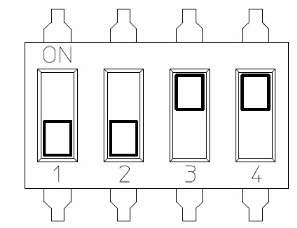 In timer mode, switch 3 or 4 must be in the ‘ON’ position. This mode allows for 3 different settings which will alter the time period for each segment.Switch 3 – Each time period represents 5 minutes.Switch 4 – Each time period represents 10 minutesSwitch 3 & 4 – Each time period represents 15 minutesController functionality in timer mode:In timer mode, the controller acts as a 4 stage run-back timer. When the controller is in stand-by mode and button is pressed, the first indicator segment will light up green, and heating is activated. When pressed again the second segment will light up and so on. Each segment is representing a time period that is selected when setting the switches.In the example below, the only switch in the ‘ON’ position would be number 3. The button would be pressed four times to activate four 15-minute segments resulting in the heater staying on for 1 hour. At the end of the last time period, the light indicators will be red for 4 seconds and then go off. The controller is now in standby mode.
 The temperature control feature will effectively maintain the set room temperature. The target temperature can be set using the variable resistor located at the back of the controller as shown below. The range is 15ºC – 35ºC. Once the room temperature reaches the set temperature, the indicators will change from green to orange. When the room temperature drops, heating will became active and the indicators will change to green.
 Temperature control for Setback periodFor this mode, the switches are set as shown below.
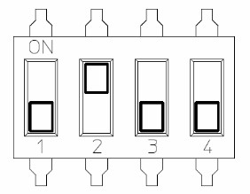 In this mode, the controller will set heating active when the room temperature drops below the set temperature. This feature can be used for frost protection or in situations where a minimum room temperature must be maintained. The setback temperature can be set using the variable resistor mounted on the back of the unit as shown above. This can be set from 0ºC – 15ºC.If the heating is active in the setback mode, the indicators will illuminate red and green.
 Temperature control for comfort and setback periods can be used individually or together. This can also be used in conjunction with the timer mode options.
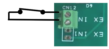 If the external input is used and the contact is closed, the indicators will light up red and stay red. When the controller is in this function, none of the modes will work apart from setback. If the contact is open the controller will function as normal.
Consort SL Wireless Controller User Manual – Consort SL Wireless Controller User Manual –
[xyz-ips snippet=”download-snippet”]